Unveiling the Power of Bluetooth PCB Boards: Design, Functionality & Applications
In our increasingly interconnected world, the Bluetooth PCB board has become a cornerstone of modern wireless technology. From our smartphones and headphones to countless IoT devices, these circuit boards enable seamless communication and data transfer, impacting our daily lives in profound ways. This article delves into the intricacies of Bluetooth PCBs, exploring their design, functionality, and diverse applications.
What is a Bluetooth PCB Board?
A Bluetooth PCB (Printed Circuit Board) serves as the foundational hardware for enabling wireless communication using Bluetooth technology. It's a meticulously engineered platform that integrates a Bluetooth module alongside the essential supporting circuitry and interfaces onto a physical board, forming a self-contained system capable of both transmitting and receiving data wirelessly.
Key Components of a Bluetooth PCB Board
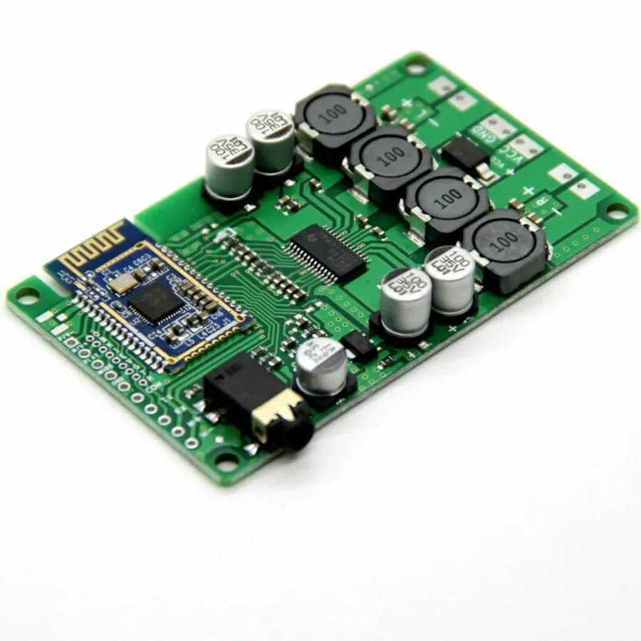
A functional Bluetooth PCB board is an intricate assembly of various components, each playing a crucial role in enabling reliable wireless communication. These components work synergistically to transmit and receive data via radio waves, adhering to the Bluetooth protocol.
- Bluetooth Chip or Module
The core of the board, responsible for handling Bluetooth protocol processing, data encoding/decoding, and radio frequency management. Modules often integrate the chip, antenna, and other components for simplified design. - Antenna
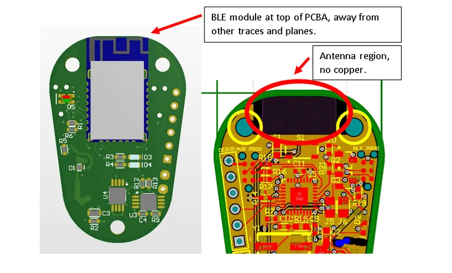
Essential for transmitting and receiving radio signals. It's carefully designed and positioned on the PCB to optimize signal strength, range, and minimize interference. It can be a trace antenna integrated directly on the PCB or a discrete component. - Power Supply Circuits
Regulates and delivers the necessary power to all components on the board. It typically includes voltage regulators, capacitors, and other components to ensure a stable and clean power supply, minimizing noise and ensuring proper functioning. - Crystal Oscillator
Provides a stable timing reference for the Bluetooth chip's operation. The precise frequency from the crystal oscillator ensures the accurate execution of data transmission and reception functions. - Data Interfaces
Provide connections for the PCB to communicate with other electronic components or external systems. These interfaces may include serial communication protocols such as UART, SPI, or I2C, as well as general-purpose input/output (GPIO) pins. - LED Indicators (Optional)
Some boards include LEDs to indicate status, connection activity or errors, providing a visual way for users to monitor the board's operation. - Passive Components
Resistors, capacitors, and inductors are used throughout the circuit to tune impedance, filter noise, and stabilize the power supply.
| Component | Function | Key Considerations |
|---|---|---|
| Bluetooth Chip/Module | Handles Bluetooth protocol and RF signals. | Power consumption, supported protocols, security features. |
| Antenna | Transmits and receives RF signals. | Placement, impedance matching, radiation pattern. |
| Power Supply Circuits | Provides stable power to all components. | Voltage regulation, noise filtering, power efficiency. |
| Crystal Oscillator | Provides a precise timing reference. | Frequency stability, accuracy, temperature drift. |
| Data Interfaces | Allows communication with external systems. | Compatibility, data rates, protocol support. |
| LED Indicators | Provides status feedback to the user. | Visibility, power consumption. |
| Passive Components | Supports circuit tuning, filtering and stabilization. | Tolerance, thermal stability, material type. |
How Bluetooth PCB Boards Facilitate Wireless Communication
Bluetooth PCB boards enable wireless communication through the transmission and reception of radio waves within the 2.4 GHz ISM (Industrial, Scientific, and Medical) band. These boards act as the physical interface for Bluetooth technology, facilitating the exchange of data by modulating and demodulating radio signals. The process involves encoding data into radio waves, transmitting them, and then decoding the received signals to retrieve the original information, establishing a seamless wireless connection.
Here's a breakdown of the communication process:
- Data Encoding
Data from the device is first converted into a digital format. This digital data is then encoded using specific modulation techniques (e.g., GFSK - Gaussian Frequency Shift Keying) to prepare it for radio transmission. - Signal Modulation
The encoded digital data is used to modulate a carrier wave. This modulation process changes the carrier wave's characteristics (e.g., frequency, phase, or amplitude) to represent the data. The resulting modulated signal is a radio wave ready for transmission. - Radio Wave Transmission
The modulated radio wave is transmitted through the antenna on the Bluetooth PCB board. The antenna is designed to efficiently radiate the radio signal into the surrounding space. - Radio Wave Reception
At the receiving end, the antenna on another Bluetooth PCB board captures the transmitted radio wave. - Signal Demodulation
The received radio wave is demodulated to extract the encoded digital data. This is the reverse process of modulation. - Data Decoding
The digital data is then decoded, reversing the encoding process to retrieve the original information. The decoded data is then available for use by the receiving device.
This entire process happens very rapidly, allowing for near real-time wireless communication between Bluetooth enabled devices. The PCB board ensures that the components for this process operate effectively and reliably.
Design Considerations for Bluetooth PCBs
Effective Bluetooth PCB design is critical for optimal performance and minimal signal interference. It requires careful attention to several key factors, including antenna placement, impedance matching, component selection, and power consumption management. These elements directly influence the reliability and range of wireless communication capabilities of the device.
| Design Parameter | Description | Importance |
|---|---|---|
| Antenna Placement | Strategic positioning of the antenna on the PCB to minimize signal loss and maximize range. | Crucial for ensuring strong and consistent wireless connectivity. |
| Impedance Matching | Matching the impedance of the antenna to the RF circuitry to ensure efficient power transfer and minimal signal reflection. | Essential for avoiding signal degradation and optimizing transmission efficiency. |
| Component Selection | Choosing suitable components with the right specifications for the Bluetooth application, such as low-noise amplifiers and filters. | Impacts signal clarity and overall system performance. |
| Power Consumption Management | Optimizing the circuit design to minimize power usage, extending battery life and promoting energy efficiency. | Vital for battery-powered devices and minimizing heat generation. |
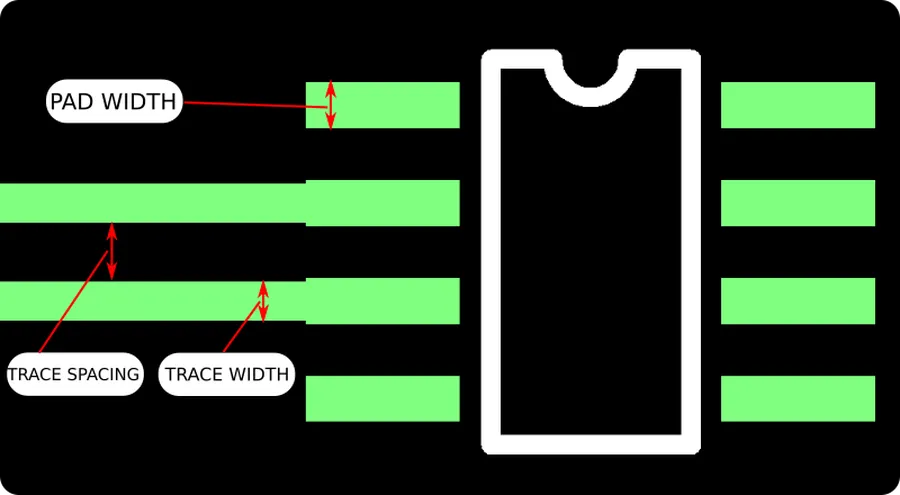
| PCB Layout | Careful routing of signal traces to minimize crosstalk and ensure signal integrity. | Reduces signal distortion and ensures reliable transmission |
These design considerations are interdependent and must be addressed holistically to create a reliable and high-performing Bluetooth PCB. Failing to optimize these aspects can lead to performance issues such as decreased range, dropped connections, and excessive power consumption.
Bluetooth PCB Board: Different Types and Modules

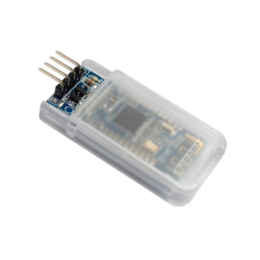
Bluetooth PCB boards come in diverse forms, primarily categorized as pre-certified modules and customized boards. The choice between these hinges on project-specific needs, development timelines, and cost considerations. Pre-certified modules offer a quicker route to implementation but with less flexibility, while custom designs provide tailored performance but require greater development effort.
| Feature | Pre-Certified Modules | Customized Boards |
|---|---|---|
| Development Time | Shorter; ready-to-integrate solutions | Longer; requires design and fabrication |
| Cost | Potentially higher per unit, lower development cost | Lower per unit cost at higher volumes, higher initial design cost |
| Flexibility | Limited; fixed configurations and form factors | High; tailored to specific application needs |
| Certification | Pre-certified for regulatory compliance | Requires independent certification |
| Size | Predetermined size | Customizable size |
| Complexity | Lower development complexity | Higher design and manufacturing complexity |
Selecting the appropriate type of Bluetooth PCB board requires careful consideration of several factors. Pre-certified modules are ideal for projects where time to market is crucial, and where standardized functionality is sufficient. Custom designs are better suited for applications with unique performance requirements, form factors, or where cost optimization at scale is paramount.
Applications of Bluetooth PCB Boards
Bluetooth PCB boards have become indispensable components in a wide array of modern electronic devices due to their ability to facilitate short-range wireless communication. The versatility of Bluetooth technology, as implemented via these PCBs, has enabled its integration into numerous sectors, enhancing convenience and connectivity across different applications.
- Consumer Electronics
This sector is arguably the most visible adopter of Bluetooth PCB boards. Headphones and earbuds rely on Bluetooth PCBs for wireless audio streaming; smartphones and tablets use them for connectivity with peripherals; smartwatches, fitness trackers, and other wearables utilize them for data synchronization and communication; and smart home devices such as smart speakers and lighting systems integrate Bluetooth PCBs for control and automation. - Automotive Systems
Bluetooth PCB boards play a crucial role in modern vehicles. They enable hands-free calling, wireless music streaming from smartphones, and integration with navigation systems. In-car diagnostics and over-the-air software updates also utilize Bluetooth connectivity for data transfer and communication. - Industrial Automation
In industrial settings, Bluetooth PCB boards facilitate wireless communication between machines, sensors, and control systems. This allows for real-time monitoring, remote control, and data logging, leading to improved efficiency and reduced operational costs. Applications range from smart factories to robotic systems and remote sensing devices. - Healthcare
Medical devices, including wearable health monitors, patient tracking systems, and diagnostic equipment, leverage Bluetooth connectivity for data transmission and remote monitoring. These applications enable healthcare professionals to track patient health metrics, remotely monitor chronic conditions, and facilitate quicker diagnoses, leading to improved patient outcomes and reduced healthcare costs. - Gaming and Entertainment
Gaming peripherals such as controllers, headsets, and virtual reality systems use Bluetooth PCBs for wireless connectivity. The technology provides a robust and low-latency connection, essential for real-time interactions. Bluetooth-enabled displays and audio systems also contribute to the overall immersive experience. - Internet of Things (IoT)
The proliferation of IoT devices relies heavily on Bluetooth connectivity. Smart sensors, environmental monitoring equipment, and home automation systems depend on Bluetooth PCBs for seamless communication. This allows for data collection, remote control, and automation, expanding the range of applications of IoT devices.
Bluetooth PCB Assembly Process
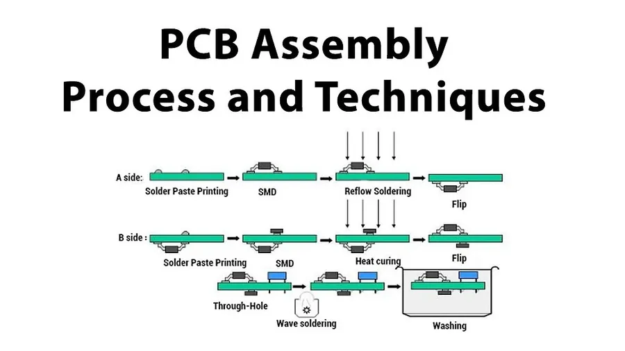
The assembly of a Bluetooth PCB involves a multi-stage process crucial for ensuring the board's functionality and reliability. This process encompasses everything from the initial design to final quality checks, and each stage is vital in producing a high-quality Bluetooth enabled product.
- PCB Design
The process begins with the PCB design, where engineers layout the circuit board using specialized software. This step involves component placement, trace routing, and ensuring signal integrity. Careful consideration is given to antenna placement and impedance matching to optimize Bluetooth signal transmission. Design choices directly impact the functionality and performance of the finished product. - PCB Fabrication
Once the design is finalized, the PCB is manufactured using a process that involves etching copper traces onto a substrate material. This process requires precision and accuracy to ensure that all traces and pads match the design specifications. This is where the physical board comes into existence. - Component Placement
After fabrication, components like the Bluetooth module, resistors, capacitors, and other integrated circuits are meticulously placed onto the PCB. This step often involves automated machinery to ensure accuracy and speed. High-precision placement is key for ensuring proper electrical connections. - Soldering
The components are then soldered onto the PCB. This process involves melting solder material to create a secure and electrically conductive connection between the components and the board. Various soldering techniques like reflow soldering are used for surface mount components. This ensures stable and reliable connections. - Testing
After soldering, each board undergoes rigorous testing to ensure it meets performance standards. This may include functional tests, signal quality measurements, and checks for connectivity issues. Testing is critical to identify any assembly or design flaws. Boards that fail testing are either repaired or discarded. - Quality Assurance
The final stage is quality assurance, where completed assemblies are checked to meet quality requirements. This includes visual inspections and functional tests. Products that pass are ready to be packaged and shipped. This final quality assurance is critical to maintain consistency and reliability of all manufactured Bluetooth PCBs.
Frequently Asked Questions About Bluetooth PCB Boards
This section addresses common questions regarding Bluetooth PCB boards, providing clear and concise answers to enhance understanding and practical application.
- What exactly is a Bluetooth PCB board?
A Bluetooth PCB (Printed Circuit Board) is the physical platform that integrates the necessary electronic components, including a Bluetooth module, antenna, and supporting circuitry, enabling wireless data transmission and reception using Bluetooth technology. It forms the core of devices utilizing Bluetooth connectivity. - Can I add Bluetooth functionality to my existing computer motherboard?
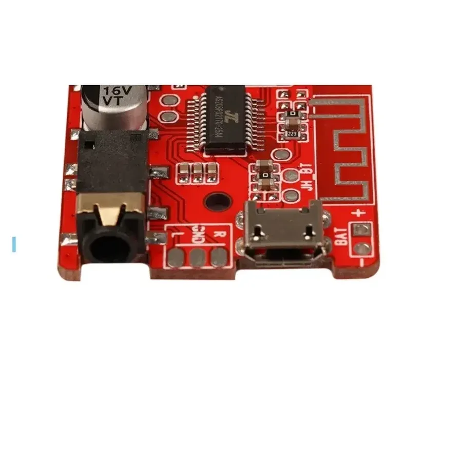
While most modern motherboards do not inherently include Bluetooth, you can add this capability through a USB Bluetooth adapter or a PCIe Bluetooth expansion card. These devices provide the necessary hardware and drivers to establish Bluetooth connectivity. - Is it possible to convert an existing amplifier to support Bluetooth audio?
Yes, this is generally feasible. You can achieve this by incorporating a Bluetooth receiver module that connects to the amplifier's audio input. This module will receive Bluetooth audio signals from your devices and transmit them to the amplifier for playback. - Can you connect to a smart board using Bluetooth?
Yes, many smart boards support Bluetooth connectivity. This allows wireless connections from devices like tablets, computers, and phones for audio, data, or other interactive functions. The exact functionality depends on the smart board's capabilities and version of Bluetooth. - What are the key design considerations when designing a Bluetooth PCB?
Key design considerations include antenna placement to maximize signal strength and minimize interference, impedance matching to ensure efficient signal transmission, careful component selection to minimize power consumption, and effective power management to ensure proper operation and longevity. These considerations ensure the PCB functions reliably and efficiently. - What are the common types of Bluetooth modules?
Bluetooth modules typically come in two main forms: pre-certified modules, which simplify integration and meet regulatory standards, and customized boards, which offer greater flexibility and cost optimization, though they require more design effort. Selecting the right module depends on specific design needs and resources. - What are the common issues encountered with Bluetooth PCB boards?
Common issues with Bluetooth PCBs can include connection failures, signal interference, and power delivery problems. Thorough testing and evaluation during and after manufacturing is essential to detect these problems. Solutions include antenna checks, re-soldering, and ensuring correct power levels.
Troubleshooting Common Bluetooth PCB Issues
Maintaining the performance and reliability of Bluetooth-enabled devices requires effective troubleshooting of common issues. These typically involve connection failures, signal interference, and power supply problems. Addressing these challenges through a systematic approach, focusing on key areas of the Bluetooth PCB, is crucial for ensuring the consistent operation of the wireless system.
- Connection Problems
Connection issues can stem from various factors. First, verify that the device attempting to connect is within the specified range of the Bluetooth PCB. Check for pairing problems by deleting existing pairings and re-pairing devices. Ensure that the Bluetooth PCB is powered on and discoverable. If using pre-certified modules, confirm compatibility and proper initialization by following the manufacturer's datasheet. - Signal Interference
Signal interference from other devices operating within the same 2.4 GHz frequency band is a common cause for performance degradation. Other wireless devices, such as WiFi routers, and microwave ovens may create interference. Try repositioning the Bluetooth PCB or the device it is connected to to reduce environmental interference. Examine the antenna of the PCB, since poor antenna design or damage could cause signal problems. Using an impedance analyzer can diagnose mismatch problems. - Power Supply Issues
An insufficient or unstable power supply can drastically affect a Bluetooth PCB's functionality. Ensure that the Bluetooth PCB receives the voltage and current within the specified range. Voltage regulators are often placed near the chip to smooth out power fluctuations. If the PCB uses a battery, confirm that the battery is fully charged, functioning correctly and connected correctly. Use a digital multimeter to verify the voltage supply to the Bluetooth module on the PCB. - Component Failure
Component failure on the PCB can lead to intermittent and difficult to diagnose problems. Inspect all components including the Bluetooth chip, crystal oscillator, power regulators and supporting passives for signs of damage or failure. Use a magnifying glass to observe the components, and measure voltages and currents near the components to diagnose the failure. If surface mount components are used, they will often require special tools to remove for replacement.
The Bluetooth PCB board is the unsung hero behind the ubiquitous wireless connections we experience daily. From its intricate design to its diverse applications, understanding this technology is key to appreciating modern electronics. As we continue to innovate and push the boundaries of wireless connectivity, Bluetooth PCB boards will undoubtedly remain a vital component in our technological future, continuing to power our interconnected lives.