Imagine the surge of water when a dam breaks – that's similar to what happens when you connect a power source to a circuit with uncharged capacitors. The sudden rush of current can be damaging. A precharge resistor is like a controlled tap, gradually filling the capacitors to protect your valuable electronics. In this article, we'll explore the vital role of the precharge resistor, a fundamental component that bridges the gap between raw power and delicate circuitry.
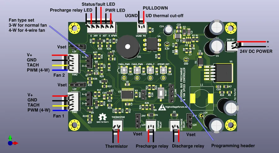
A precharge resistor is a critical component in electrical circuits, primarily employed to control the inrush current during the initial charging phase of capacitors. By limiting this initial current surge, it prevents damage to both the capacitors and other circuit components, ensuring a safer and more reliable system operation. This is essential in high-power applications such as inverters, electric vehicles, and variable frequency drives where large capacitor banks are routinely charged.
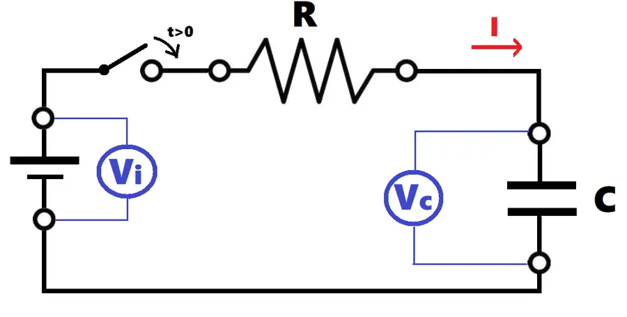
Precharge resistors are indispensable components in electrical circuits, primarily functioning to mitigate the damaging effects of inrush current during capacitor charging. Without these resistors, the initial surge of current can lead to component failure, system instability, and reduced lifespan of electrical equipment, particularly in systems with high capacitance such as electric vehicles and power supplies.
Consider a scenario where a large capacitor bank is directly connected to a power source. Upon connection, the uncharged capacitors act as a short circuit, leading to a rapid and uncontrolled current flow. This inrush current can exceed the safe operating limits of various components, potentially causing damage to capacitors, contactors, semiconductors, and power supplies. The inclusion of a precharge resistor introduces a controlled impedance, limiting this initial current surge to a safe level, allowing capacitors to charge gradually, thereby safeguarding the circuit.
| Scenario | Without Precharge Resistor | With Precharge Resistor |
|---|---|---|
| Initial Capacitor Charging | Sudden, high inrush current causing potential damage. | Controlled, limited inrush current enabling safe charging. |
| Component Stress | High stress on contactors, capacitors and semiconductors. | Reduced stress on system components increasing component life. |
| System Reliability | Potential system instability and failures due to current surges. | Improved system reliability due to controlled charging process. |
| Application examples | May be found in older low voltage circuits, or applications that do not need it. | Ubiquitous in high power applications such as EVs and industrial motor controls. |
In electric vehicles (EVs), the high-voltage battery systems contain large capacitor banks within the inverter and other power electronic components. When the vehicle is switched on or during charging, the large voltage differential could cause huge inrush currents without precharge protection. These currents could seriously damage the system and cause premature failure of expensive components. Precharge resistors are therefore vital in EVs for managing the initial charging of these capacitors and are therefore an essential safety component. Similarly, in industrial power supplies and Variable Frequency Drives (VFDs), precharge resistors are equally crucial to ensure the system's longevity and operational safety by protecting against inrush currents.
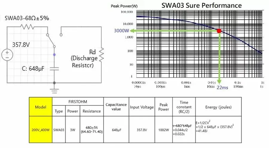
A precharge resistor is strategically placed within an electrical circuit to manage the initial flow of current when a circuit is energized, predominantly during the charging of capacitors. This controlled current flow is critical in preventing damage and ensuring the longevity of circuit components by limiting inrush current, specifically interacting with capacitors and contactors to achieve this.
The functional process unfolds in a sequence; initially, when the power source is engaged, the precharge resistor limits the current flowing into the circuit’s capacitors. This occurs because the capacitors, when uncharged, act as a short circuit, potentially drawing extremely high currents that could harm the system. By introducing resistance into the circuit pathway, the precharge resistor ensures that the capacitors charge at a controlled rate. Once the capacitors are adequately charged and the inrush current has subsided to a safe level, a contactor (or relay) bypasses the precharge resistor. This step allows the circuit to operate at its intended current levels and proceed to power the load efficiently.
| Component | Function During Precharge | Function After Precharge |
|---|---|---|
| Precharge Resistor | Limits inrush current to charge capacitors safely | Bypassed, no longer in the main current path |
| Capacitors | Accumulate charge gradually at a controlled rate | Charged and prepared for normal circuit operation |
| Contactor (or Relay) | Open circuit to bypass resistor initially | Closes to allow full current through the circuit, bypassing the precharge resistor. |
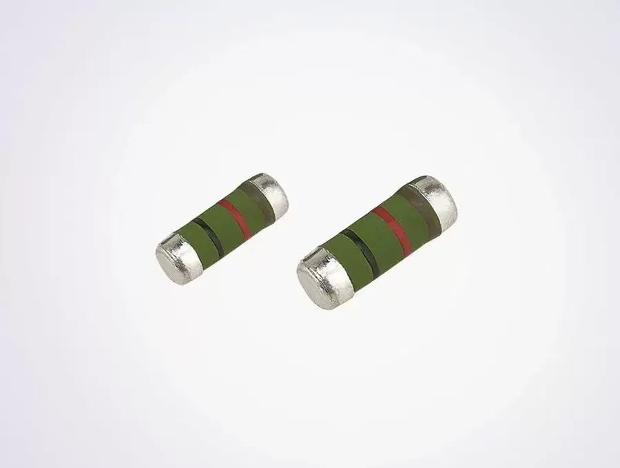
Selecting the correct precharge resistor is critical for the reliable and safe operation of electrical systems. The primary function of this resistor is to limit inrush current during capacitor charging, preventing damage to components and ensuring system stability. The selection process involves a careful consideration of several key factors, each contributing to the overall performance and longevity of the system.
The primary factors influencing precharge resistor selection are resistance value, power rating, and tolerance. These parameters must be chosen according to the specific system requirements, and the type of application.
| Factor | Description | Importance |
|---|---|---|
| Resistance Value | The Ohmic value of the resistor, which determines the rate of capacitor charging and the inrush current. Measured in Ohms (Ω). | Directly affects the charging time and peak inrush current. Too low can cause excessive inrush current, damaging components. Too high extends charge time, leading to potential system start-up issues. |
| Power Rating | The amount of power the resistor can dissipate safely without overheating or failing. Measured in Watts (W). | Must be sufficient to handle the energy dissipated during the charging process. If the power rating is inadequate, the resistor can fail due to overheating. |
| Tolerance | The allowable variation in the actual resistance value from its stated value. Expressed as a percentage (%). | Affects the precision of the charging circuit. Lower tolerance is critical for accurate charging in precise applications. |
For example, in variable frequency drives (VFDs) or inverters, the precharge resistor must be able to withstand higher voltage levels and handle the capacitor bank's capacitance. In contrast, electric vehicle (EV) systems demand robustness and reliability due to high-power charging. The resistor's physical size and material must also be taken into consideration for thermal management and mechanical robustness.
Correctly specified precharge resistors, are essential to protect the inverter components and capacitors within the system. The choice of a precharge resistor ensures the reliable and safe startup of these systems.
Calculating the correct precharge resistor value is crucial for safe and efficient capacitor charging, preventing excessive inrush current that can damage components. This calculation depends primarily on the system's voltage and the capacitance being charged, with adjustments for different load types.
The fundamental goal of the precharge resistor is to limit the initial current flow when a discharged capacitor is connected to a voltage source. Without a precharge resistor, the initial current can be extremely high (theoretically infinite for an ideal capacitor). This high current can cause damage to the capacitor, the power source, or other circuit components. The precharge resistor slows the charging process, allowing the capacitor voltage to gradually increase and reducing the initial surge.
The basic formula to calculate the precharge resistance is based on the desired time constant for charging the capacitor and the system parameters. The time constant (τ) is defined as the time it takes for the capacitor to charge to approximately 63.2% of the source voltage. A shorter time constant implies faster charging, which requires a lower resistance value.
The precharge resistance (R) is determined by the time constant (τ) and capacitance (C) using the formula: R = τ / C. Choosing the desired time constant is determined by balancing acceptable charging times with the need to minimize inrush current. Generally, the time constant is chosen based on system specifications and safe limits of the connected devices. Once the desired time constant is selected, the value of the resistor can be calculated using this formula.
While the time constant is based on a percentage of the maximum voltage, the selection of the resistor is also influenced by the current. The maximum current during precharge is determined by Ohm's Law: I = V / R, where V is the source voltage and R is the precharge resistance. Therefore, it is critical to select a resistor that can handle the initial current and withstand the associated power dissipation. This power dissipation is calculated as P = I^2 * R. Select a resistor with a power rating significantly higher than the calculated power dissipation.
| Factor | Description | Impact on Resistance Calculation |
|---|---|---|
| System Voltage (V) | The voltage of the power source. | Higher voltage typically requires a higher resistance to limit current. The voltage directly relates to the current calculation (I = V/R). |
| Capacitance (C) | The total capacitance being charged. | Larger capacitance requires a lower resistance to achieve the same charge time, but it also increases the initial current and requires more power dissipation. |
| Desired Time Constant (τ) | The target time for the capacitor to charge to a certain voltage. | A shorter time constant requires lower resistance and may require a higher power rating for the resistor. |
| Maximum Current (Imax) | The maximum allowable current that the system can handle. | This value dictates the minimum required resistance and the power rating of the resistor. The precharge resistor must be selected to limit the current to or below the Imax value. |
| Power Rating (P) | The power the resistor must be able to dissipate | Resistor needs to be able to handle the power produced at the current produced at startup without overheating or failure. |
Precharge resistance calculation must consider the differences in behavior of various types of load. Constant power loads, such as DC-DC converters, draw a stable power, where as, a capacitor will have a high inrush at the start of charging, then decrease. These differences significantly influence the choice of precharge resistance. In constant power loads, calculating precharge resistance will typically take into account both the starting resistance for any inrush current and the resistance at the rated operating power to ensure that the charging process is not too slow, or the operating power too high.
For example, in the case of a capacitor, the precharge resistance is selected to meet the time constant of the capacitor charging process, while with a DC-DC converter, the precharge resistance must consider the initial inrush current and the required operating current. The precharge design should address the initial high current for the capacitor, while taking into consideration the steady state power level for the converter to ensure optimal operation.
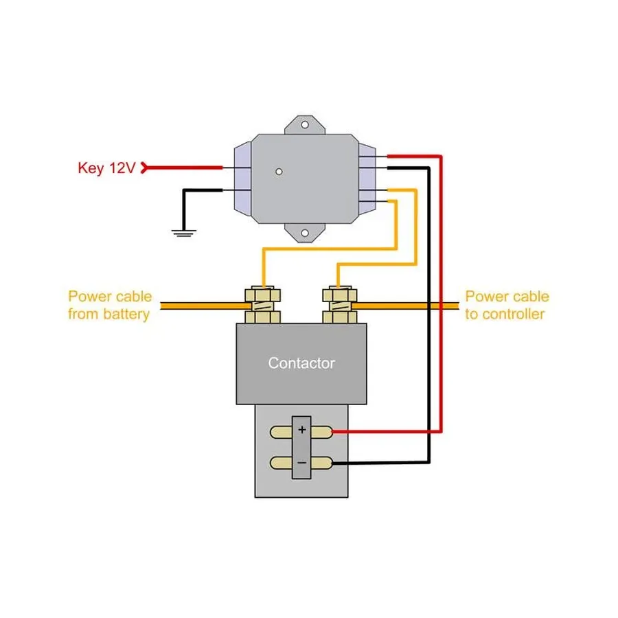
The strategic placement of a precharge resistor—either before or after the main contactor—significantly impacts circuit behavior and safety. The optimal position depends on balancing factors like current control, contactor protection, and system architecture, each offering distinct advantages and disadvantages.
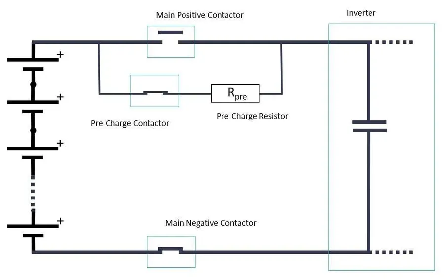
In Electric Vehicles (EVs), precharge resistors are vital for managing the high-voltage battery systems during the initial charging phase. They serve to limit the inrush current when the main contactor is closed, preventing damage to sensitive electronic components and ensuring the longevity of the system. This controlled charging process is essential for the safe operation of the high-voltage system.
The precharge process in EVs typically involves the following steps: Upon activation, power is initially supplied through the precharge resistor, slowly charging the DC-link capacitors. Once the capacitors are sufficiently charged, the main contactor is activated, providing the full current path to the load. The precharge resistor is subsequently bypassed, thus minimizing power losses in normal operation.
| Feature | Traditional Contactors | Solid-State Relays |
|---|---|---|
| Switching Speed | Relatively slow | Very fast |
| Lifespan | Limited by mechanical wear | Longer due to no moving parts |
| Reliability | Susceptible to contact bouncing and wear | More reliable, less susceptible to wear |
| Complexity | Simpler circuitry | More complex control circuitry |
| Cost | Generally lower | Higher initial cost |
| Size and Weight | Bulkier and heavier | Smaller and lighter |
While traditional contactors are often used in EV systems due to their lower cost and simplicity, solid-state relays (SSRs) offer significant advantages in terms of speed and reliability. SSRs provide much faster switching speeds and are more reliable due to the lack of moving parts, leading to enhanced system performance and longevity. However, SSRs have a higher initial cost and require more complex control circuitry, which needs to be carefully considered during system design.
This section addresses common questions regarding precharge resistors, clarifying their roles in various applications such as Variable Frequency Drives (VFDs), the impact of resistor sizing, and best practices across different voltage levels. These practical insights are essential for effective implementation of precharge resistors in diverse electrical systems.
Precharge resistors, while seemingly simple components, are crucial for the safe operation of electrical systems. When they fail, it often indicates a deeper issue within the circuit. Effective troubleshooting requires a systematic approach to identify the failure mode, its cause, and apply appropriate corrective actions. Understanding common failure symptoms and testing methodologies is crucial for maintaining the reliability of the system.
When a precharge resistor fails, it often presents specific symptoms, which can point to the root cause. Identifying these symptoms early on can help prevent further damage. Here are some common fault symptoms:
Testing a precharge resistor should be done when symptoms indicate a possible issue or during regular maintenance. The following testing methods are recommended:
The precharge resistor, often overlooked, is a critical safety component in numerous applications, protecting circuits from damaging inrush current. Understanding its principles, selection, and placement ensures safe and efficient operation of electrical systems. As we continue to rely on increasingly complex and powerful electronic devices, the role of the humble precharge resistor will become even more significant. By carefully incorporating and maintaining precharge resistors, we safeguard our technology against damaging power surges.

