In our modern world, electronic devices are integral to daily life, and at the heart of many of these devices lies the crucial component – the rectifier diode. Like a one-way street for electricity, it transforms alternating current (AC) from your wall outlet into the direct current (DC) your electronics need, seamlessly powering our homes and industries. In this article, we will explore the world of rectifier diodes, uncovering their mechanism, applications, and how they help shape the electrical landscape.
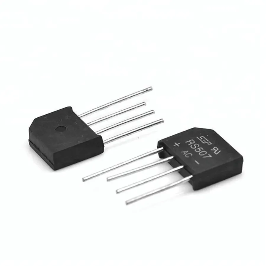
Rectifier diodes are fundamental semiconductor devices engineered to facilitate unidirectional current flow, thus enabling the crucial conversion of alternating current (AC) to direct current (DC). This essential functionality arises from the diode's inherent PN junction, which establishes distinct electrical behaviors at its two terminals: the anode and the cathode.
The PN junction, a core component of a rectifier diode, is formed by joining a p-type and n-type semiconductor material. When a positive voltage is applied to the anode relative to the cathode (forward bias), the diode allows current to flow easily. Conversely, when the voltage polarity is reversed (reverse bias), the diode acts as a high resistance barrier, effectively blocking current flow.
| Characteristic | Description |
|---|---|
| Material | Semiconductor (typically Silicon or Germanium) |
| Function | Allows current flow in one direction only |
| Terminals | Anode (+) and Cathode (-) |
| PN Junction | Formed by joining p-type and n-type semiconductor |
| Forward Bias | Low resistance, allows current to pass |
| Reverse Bias | High resistance, blocks current |
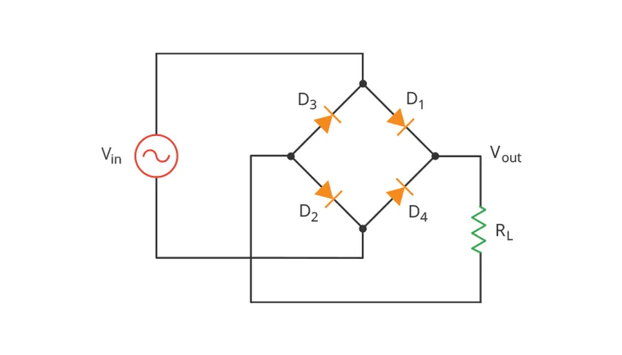
Rectifier diodes, at their core, are semiconductor devices that leverage the unique properties of a PN junction to enable unidirectional current flow, crucial for converting alternating current (AC) to direct current (DC). This behavior is dictated by the concepts of forward and reverse bias, and understanding these concepts is key to comprehending how these diodes rectify current.
The PN junction of a rectifier diode is formed by joining a P-type semiconductor (doped with acceptor impurities) and an N-type semiconductor (doped with donor impurities). This junction creates a depletion region, an area devoid of free charge carriers. The behavior of this region dictates the overall function of the diode, acting as a kind of electrical valve.
When a positive voltage is applied to the P-type material (anode) with respect to the N-type material (cathode), the diode is said to be in forward bias. This causes the depletion region to shrink, allowing current to flow easily through the diode with minimal resistance. The energy barrier at the junction is overcome, permitting electrons to move from the N-side to the P-side and holes to move from the P-side to the N-side, causing current flow.
In contrast, when a negative voltage is applied to the P-type material, the diode is in reverse bias. The depletion region expands, significantly increasing the resistance to current flow. In this state, the diode effectively blocks current, allowing only a tiny leakage current to flow. The energy barrier at the junction becomes too large for charge carriers to cross, thus stopping current flow.
This asymmetrical conductance is the fundamental principle of rectification. AC current periodically changes direction, but when passed through a rectifier diode, the diode allows current to flow only when it's in the forward bias, effectively eliminating one half of the AC cycle. The resulting current, while not a perfect DC, is a pulsating DC which can then be further filtered and regulated for various applications.
The rapid switching between conduction and blocking states when the polarity of the AC source changes, along with the specific voltage drop during forward conduction and its high reverse blocking voltage capabilities, are the core characteristics that make rectifier diodes suitable for transforming AC power into DC power. The efficiency of this conversion depends on the diode's characteristics and the specific circuit configuration used.
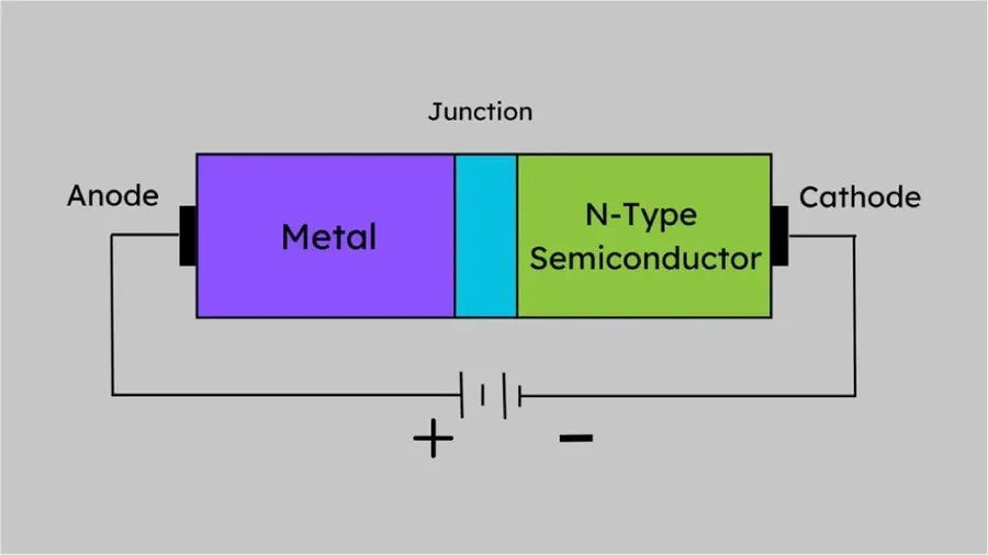
Rectifier diodes are not a monolithic entity; they are available in various types, each tailored to specific performance requirements. These variations primarily revolve around their construction and materials, which dictate their electrical characteristics. Understanding these differences is critical for selecting the appropriate diode for a given application.
| Type | Forward Current (Iₑ) | Reverse Voltage (Vₑ) | Switching Speed | Typical Applications |
|---|---|---|---|---|
| Standard Rectifier Diode | Moderate | Moderate to High | Relatively Slow | General-purpose rectification, low-frequency power supplies |
| Fast Recovery Diode | Moderate | Moderate to High | Faster than Standard Diodes | Switching power supplies, high-frequency rectification |
| Schottky Diode | Moderate | Low | Very Fast | High-frequency rectification, low voltage power supplies, solar power |
Selecting the proper type of rectifier diode requires a careful analysis of the application's voltage and current requirements, as well as operational frequency. Standard diodes are adequate for low-frequency applications with modest current requirements, while Schottky diodes are used for high-speed, low-voltage circuits where efficiency is a priority. Fast recovery diodes bridge the performance gap, offering improvements in switching speed compared to standard types.
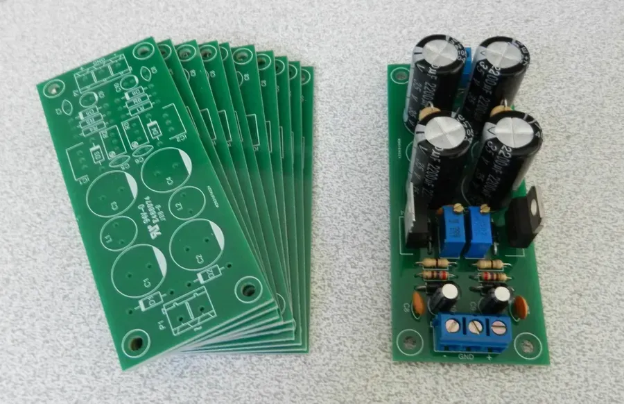
Rectifier diodes are fundamental components in numerous electronic systems, primarily due to their ability to convert alternating current (AC) into direct current (DC). This unidirectional current flow characteristic makes them indispensable in any application that requires a stable DC power source from an AC supply. Their versatile nature means you will encounter them in everyday household electronics, industrial power transmission systems, and critical automotive circuits.
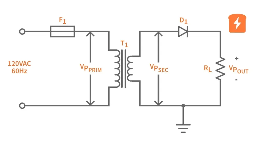
Rectifier circuits utilize diodes to convert alternating current (AC) into direct current (DC). The choice of circuit configuration, such as half-wave, full-wave, or bridge rectifiers, significantly impacts the efficiency and quality of the rectified DC output. Each configuration has unique characteristics, advantages, and drawbacks, making the selection dependent on specific application requirements.
| Circuit Configuration | Number of Diodes | Efficiency | Output Characteristics | Advantages | Disadvantages |
|---|---|---|---|---|---|
| Half-Wave Rectifier | 1 | 40.6% | Pulsating DC with significant ripple | Simple design, low cost | Low efficiency, high ripple content, requires large filter capacitors, only utilizes one half of AC cycle |
| Full-Wave Rectifier (Center-Tapped) | 2 | 81.2% | Less ripple than half-wave, smoother DC output | Higher efficiency compared to half-wave, utilizes both half cycles | Requires a center-tapped transformer, higher component count than half-wave |
| Full-Wave Bridge Rectifier | 4 | 81.2% | Smoother DC output with less ripple, more efficient than half-wave | High efficiency, no center-tapped transformer required, uses both half cycles of AC input | Higher component count |
The half-wave rectifier is the simplest, using a single diode to pass only one half of the AC waveform. This simplicity comes at the cost of low efficiency and high ripple in the output DC, requiring substantial filtering. Full-wave rectifiers, employing either a center-tapped transformer with two diodes or a bridge configuration with four diodes, utilize both halves of the AC cycle, providing a more efficient and smoother DC output, though at a slightly increased component cost. The bridge rectifier is particularly versatile as it does not need a center-tapped transformer. The choice of rectifier type thus becomes a trade-off between circuit complexity, efficiency, and required output quality.
Accurately testing and troubleshooting rectifier diodes is crucial for maintaining the reliability of electronic circuits. This section provides a comprehensive guide on using a multimeter to assess diode functionality and identifying potential failure points, as well as using a basic circuit model to observe performance.
A rectifier diode’s primary function is to allow current flow in one direction (forward bias) and block it in the opposite direction (reverse bias). Testing involves verifying this behavior using a multimeter.
A common failure mode for a rectifier diode is either an open circuit, preventing current flow in both directions, or a short circuit allowing current in both directions. These faults will disrupt the expected AC to DC conversion process. Another common failure involves a forward voltage drop that exceeds the datasheet specifications which reduces the efficiency of the rectification.
| Test | Multimeter Reading (Ideal Diode) | Interpretation |
|---|---|---|
| Forward Bias | 0.6-0.7V (Silicon) / 0.2-0.3V (Schottky) | Indicates proper forward conduction |
| Reverse Bias | OL or Infinite Resistance | Indicates proper reverse blocking |
| Open Circuit Test | OL or Infinite Resistance in both directions | Indicates a broken or disconnected diode |
| Short Circuit Test | 0 resistance in both directions | Indicates a shorted diode |
A simple circuit model, consisting of a rectifier diode in series with a resistor and an AC source, can be built to visually observe the diode’s function with an oscilloscope. By observing the output waveform, you can confirm whether rectification is occurring.
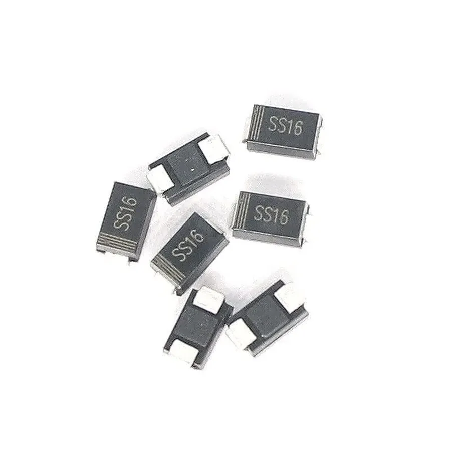
Selecting the appropriate rectifier diode for a given application requires a thorough understanding of several key parameters and operational conditions. Proper diode selection ensures optimal circuit performance, reliability, and longevity. This section details the essential factors to consider when choosing a rectifier diode, enabling engineers and designers to make informed decisions.
Key factors to consider when selecting a rectifier diode include:
| Parameter | Description | Impact on Circuit Design |
|---|---|---|
| Peak Inverse Voltage (PIV) | Maximum reverse voltage diode can withstand | Avoid breakdown; select with safety margin |
| Forward Current (IF) | Maximum forward current the diode can handle | Prevent overheating and failure; choose adequate rating |
| Average Rectified Forward Current (IO) | Average current during rectification cycles | Select based on application-specific average current needs |
| Forward Voltage Drop (VF) | Voltage drop across diode when conducting | Minimize power loss; use lower VF for high-current applications |
| Reverse Recovery Time (trr) | Time to stop conducting from forward to reverse | Critical in high-frequency circuits; fast recovery diodes preferred |
| Operating Temperature | Temperature range for reliable operation | Ensure operating conditions within range; avoid overheating |
| Package Type | Physical housing and connection type | Impacts thermal performance, mounting, and space |
| Thermal Characteristics | Thermal resistance from junction to ambient and junction to case | Helps manage heat dissipation; critical for high-power applications |
By meticulously assessing each of these criteria, engineers can confidently select a rectifier diode that meets the specific demands of their application, ensuring the system operates efficiently and reliably.
This section addresses common queries regarding rectifier diodes, clarifying their functionality, applications, and differences compared to other diode types. These answers are based on fundamental principles of semiconductor physics and electrical engineering.
The rectifier diode, a seemingly simple component, plays a vital role in modern electronics by enabling the conversion of AC power to DC. From the smallest gadgets to large industrial machinery, rectifier diodes are indispensable. By mastering their principles and applications, we can gain a deeper understanding of electronics and appreciate the intricate workings of the devices that power our world. The future of the rectifier diode is likely to focus on efficiency and miniaturization, continuing to play its essential role.

