SMD Components: A Deep Dive into Surface Mount Technology
2025.01.22
In our increasingly miniaturized world, Surface Mount Devices (SMD) are the unsung heroes of modern electronics. From the smartphone in your pocket to the complex systems in a satellite, SMD components like resistors, capacitors, and inductors are the building blocks of countless devices. This article dives into the world of SMD components, demystifying their function, identification, and why they’re indispensable in today's technology landscape. Let's explore this fascinating area of electronic engineering and see how these tiny pieces form the basis of nearly every modern device.
What are SMD Components?
Surface Mount Components
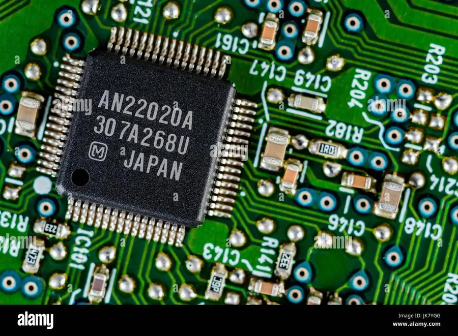
Surface Mount Devices (SMD) are electronic components designed to be mounted directly onto the surface of a printed circuit board (PCB), contrasting with traditional through-hole components that have leads inserted through holes in the board. This fundamental shift in component design is at the heart of Surface Mount Technology (SMT), revolutionizing electronics manufacturing by enabling smaller, more densely populated, and more efficient circuit boards. SMD components are characterized by their flat, leadless or short-leaded design, facilitating automated assembly processes and contributing to the miniaturization trend in modern electronics.
The transition from through-hole to surface-mount technology has been driven by the need for increased circuit density, improved manufacturing efficiency, and reduced production costs. SMDs, therefore, represent a key element in modern electronics, with their small size and precise placement requirements enabling the creation of compact and sophisticated electronic devices.
Types of SMD Components
SMD Resistors and Capacitors
Surface Mount Devices (SMD) encompass a wide array of electronic components, each designed for specific functions within a circuit. Unlike their through-hole counterparts, SMDs are soldered directly onto the surface of a printed circuit board (PCB), enabling compact and efficient electronic designs. This section details the common types of SMDs and their respective roles.
SMD Resistors Resistors limit current flow and provide voltage division. They are fundamental components in electronic circuits, identified by their resistance value and tolerance. SMD resistors are available in various sizes and tolerances, often marked with numerical codes indicating their resistance.
SMD Capacitors Capacitors store electrical energy and are used for filtering, decoupling, and timing. They are categorized based on the dielectric material used, influencing their properties such as capacitance, voltage rating, and temperature stability. Common types include ceramic, tantalum, and electrolytic capacitors.
SMD Inductors Inductors store energy in a magnetic field and are used in filters, oscillators, and power supply circuits. Their key parameters are inductance and current rating. SMD inductors are typically categorized by their core type and physical dimensions.
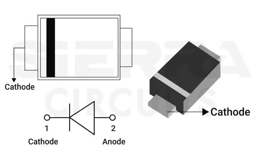
SMD Diodes Diodes allow current to flow in one direction only and are used for rectification, switching, and signal modulation. SMD diodes include general-purpose diodes, Schottky diodes, and Zener diodes, each with unique operating characteristics.
SMD Transistors Transistors amplify or switch electronic signals and power. SMD transistors include bipolar junction transistors (BJTs) and field-effect transistors (FETs), each available in a variety of configurations and performance characteristics.
SMD Integrated Circuits (ICs) ICs contain numerous transistors, resistors, and other components in a single package, performing complex functions. SMD ICs range from simple logic gates to microprocessors and application-specific integrated circuits (ASICs), and are crucial in modern electronic design.
SMD Component Sizes and Packages
SMD Packages
Surface Mount Device (SMD) components are manufactured in standardized sizes and package types, each designed to meet specific performance requirements and assembly constraints. These standardized dimensions facilitate automated assembly processes and ensure compatibility across different manufacturing setups. The size and package of an SMD component directly impacts its electrical characteristics, thermal behavior, and the overall density of a printed circuit board (PCB).
Package Code
Length (mm)
Width (mm)
Typical Applications
Notes
0201
0.6
0.3
High-density boards, mobile devices
Smallest commonly used size
0402
1.0
0.5
Compact consumer electronics
Small, but easier to handle than 0201
0603
1.6
0.8
General-purpose electronics
Popular choice for many applications
0805
2.0
1.25
Automotive, industrial applications
Slightly larger, easier to solder
1206
3.2
1.6
Power circuits, more robust
Offers better power handling
1210
3.2
2.5
High power applications
Larger footprint for increased power disipation
1812
4.5
3.2
High voltage circuits
Larger for greater voltage and heat handling
2512
6.3
3.2
Current sensing, power resistors
Suitable for higher power requirements
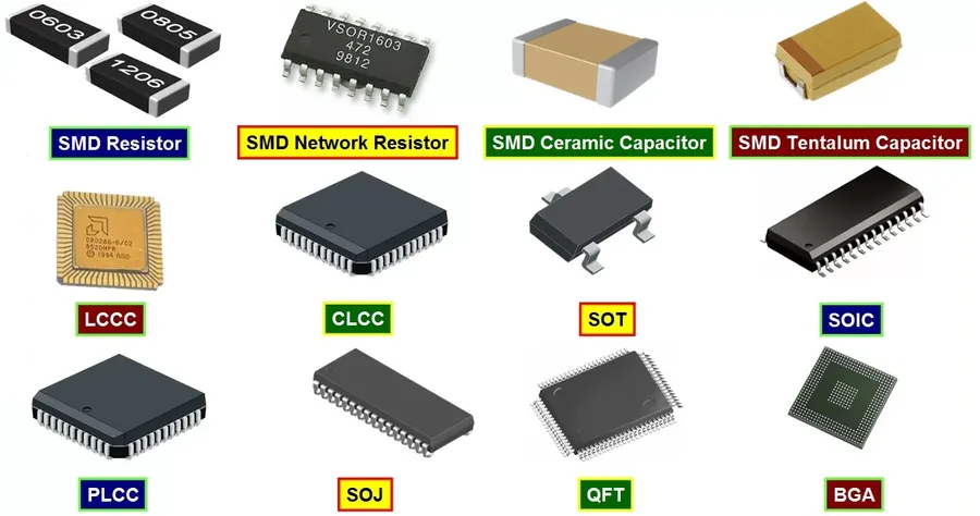
Beyond the basic rectangular packages used for resistors and capacitors, SMD components come in a variety of other package types. These include: SOT (Small Outline Transistor) packages for transistors and diodes, SOIC (Small Outline Integrated Circuit) packages for ICs, QFP (Quad Flat Pack) packages for higher pin-count ICs, and BGA (Ball Grid Array) packages for very high density and complex circuits. The selection of a package type depends heavily on the component's function, electrical characteristics and the assembly requirements.
Identifying SMD Components
SMD Markings
Accurately identifying Surface Mount Device (SMD) components is crucial for effective circuit board repair, assembly, and design. SMD components, unlike their through-hole counterparts, lack wire leads, requiring precise identification based on their physical markings, color codes, and geometric characteristics. This section provides practical methods to correctly identify these miniaturized electronic parts.
SMD component identification relies on a combination of visual inspection and knowledge of industry-standard markings and codes. The methods include:
Component Markings Many SMD components have alphanumeric codes printed on their bodies. These codes often denote the component's value, tolerance, or manufacturer. These markings are typically very small and may require magnification for accurate reading.
Resistor Color Codes Some SMD resistors employ a color band system, similar to that used on through-hole resistors, though typically much smaller. The color sequence provides the resistance value and tolerance. For example, four-band and five-band color codes are common, requiring careful interpretation using a color code chart.
Component Geometry The physical shape and size of an SMD component can offer initial clues to its identity. The component's package type (e.g., 0603, 0805, 1206) and overall dimensions are crucial indicators. For instance, a small rectangular chip with two terminals is likely a resistor or capacitor, whereas an elongated component with multiple leads may be an IC or transistor.
Manufacturer's Datasheets The most accurate way to identify an SMD component is by referring to the manufacturer’s datasheet. Datasheets contain detailed information on the component’s specifications, package type, pinout, and markings. Using the markings on the component to search the manufacturer's online database can provide a definitive identification.
A visual guide, such as an identification chart, can be very beneficial, especially for beginners. These charts typically show common SMD component types, their package sizes, and typical markings. When dealing with very small components, using a magnifying glass, microscope, or macro camera can significantly aid in reading markings and identifying component geometry.
The SMT Assembly Process
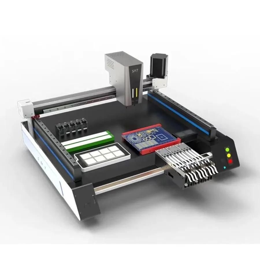
Pick and Place Machine
Surface Mount Technology (SMT) assembly is a sophisticated process that automates the placement and soldering of Surface Mount Devices (SMD) onto printed circuit boards (PCBs). This method is pivotal in modern electronics manufacturing, enabling smaller, more densely populated, and higher-performing electronic devices compared to traditional through-hole technology.
The SMT assembly process can be broken down into several key stages, each requiring precision and control:
Solder Paste Application A precisely measured amount of solder paste, a mixture of solder powder and flux, is applied to the PCB pads where SMD components will be placed. This is typically done using a stencil and a squeegee or via jet printing for more precision.
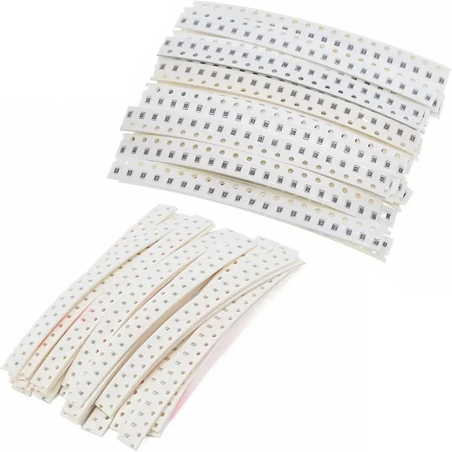
Component Placement Automated pick-and-place machines, equipped with vacuum nozzles and vision systems, accurately pick SMD components from tape reels or trays and place them onto the solder paste-covered pads. This stage requires high precision to ensure components are correctly aligned.
Reflow Soldering The populated PCB is passed through a reflow oven, where it is heated according to a precisely defined temperature profile. This controlled heating melts the solder paste, forming a strong electrical and mechanical bond between the SMD components and the PCB pads. The profile is critical to ensure proper solder wetting and prevent component damage.
Cleaning and Inspection After reflow, the PCB may require cleaning to remove any residual flux. Automated optical inspection (AOI) or X-ray inspection is then performed to detect any soldering defects, missing components, or misalignment. This ensures the quality and reliability of the final product.
SMT offers significant advantages over through-hole technology:
Miniaturization SMD components are significantly smaller than their through-hole counterparts, allowing for more compact and densely populated PCBs.
Automation The SMT assembly process is highly automated, leading to increased production efficiency, reduced labor costs, and improved repeatability and consistency.
Improved Performance The reduced size and shorter leads of SMD components contribute to better electrical performance, including reduced parasitic inductance and capacitance, particularly in high-frequency applications.
Practical SMD Soldering Techniques
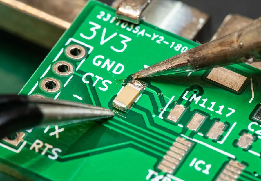
Hand Soldering SMD
Successfully soldering Surface Mount Devices (SMD) requires precision and the right techniques. This section offers a step-by-step guide for both beginners and experienced users, detailing the necessary tools, useful tips, and various methods including soldering iron, hot air rework station, and reflow oven techniques.
Soldering Iron Method The soldering iron method is suitable for larger SMD components and beginners. Key steps include:
1. **Preparation:** Clean the PCB pads and component leads.
2. **Tinning:** Apply a small amount of solder to one pad on the PCB.
3. **Component Placement:** Carefully position the SMD component on the tinned pad.
4. **Soldering:** Heat the component lead and PCB pad simultaneously, and apply solder until a good joint is formed.
5. **Finalize:** Repeat for remaining leads.
Hot Air Rework Station Method The hot air rework station is ideal for smaller SMD components and reflowing multiple joints simultaneously. Key steps include:
1. **Preparation:** Apply flux to the PCB pads.
2. **Component Placement:** Position the component accurately on the pads.
3. **Heat Application:** Use hot air to heat the component and pads until the solder melts and forms joints.
4. **Cooling:** Allow the joint to cool without moving the component.
Reflow Oven Method A reflow oven is used for mass production and multiple component soldering at once. Key steps include:
1. **Solder Paste Application**: Apply solder paste to the PCB pads using a stencil.
2. **Component Placement:** Place the SMD components onto the paste.
3. **Reflow Process:** Place the board in the reflow oven, following a specific temperature profile to melt the solder and form secure connections.
4. **Cooling:** Allow the board to cool down.
Method
Best Use Cases
Difficulty
Tools Required
Soldering Iron
Larger SMD components, Beginners
Easy
Soldering Iron, Solder, Flux
Hot Air Rework Station
Smaller SMD components, Reflow multiple joints
Medium
Hot Air Station, Flux
Reflow Oven
Mass Production, Multiple Components
Advanced
Reflow Oven, Solder Paste, Stencil
Where to Source SMD Components
Sourcing authentic SMD components is crucial for reliable electronic product manufacturing and repair. This section provides guidance on identifying dependable suppliers, both online distributors and alternative sources, to ensure the procurement of genuine components.
The market offers a multitude of suppliers, but not all are created equal. Some may sell counterfeit parts that can lead to product failure or even safety issues. Therefore, due diligence is paramount. Here, we explore channels and methodologies to procure SMD components safely and reliably.
Online Distributors Established online distributors offer vast catalogs of SMD components. These suppliers are typically reputable and provide genuine parts, often with datasheets and technical specifications readily available. Examples include Digi-Key, Mouser Electronics, and Arrow Electronics. These distributors maintain comprehensive inventory, offer competitive pricing, and have robust shipping and return policies. Their websites often include advanced search tools that allow for precise part selection by specifying parameters like package size, value, and tolerance. Furthermore, these distributors offer traceability and certifications, ensuring component quality.
Manufacturer Direct For larger-scale projects or specific requirements, sourcing directly from component manufacturers may be a viable option. While direct sourcing may not be feasible for small-scale projects, it can ensure the authenticity of components and may offer pricing advantages for large-volume purchases. Manufacturers often have strict quality control processes and can provide comprehensive documentation for their products. Direct sourcing requires establishing relationships with manufacturers and may involve longer lead times for production and delivery. However, this route can be advantageous for customized components or special orders that are not readily available through distributors.
Authorized Resellers Authorized resellers are another viable source, particularly for smaller quantities. Resellers are generally distributors or smaller companies approved by the manufacturers to sell their parts. While they may not offer the same breadth of inventory as online distributors, authorized resellers can provide competitive pricing and personalized service. When sourcing through resellers, it's important to verify their authorization status to ensure authenticity of the parts. Contacting manufacturers directly to confirm their authorized distributors is often good practice.
Reputable Brokers Brokers can be useful to find hard-to-source components. While some brokers specialize in obsolete and end-of-life components, working with brokers carries higher risks. Thorough due diligence is important to ensure the broker's reputation, and it is also wise to check components for authenticity upon delivery. It is generally not advisable to use brokers as primary source of common SMD parts.
Alternative Sources Alternative sources may include electronic waste recycling, surplus inventory, and specialized marketplaces, though these require careful validation and testing to ensure reliability. Components recovered from electronic waste can be viable for prototyping and some hobbyist applications but should not be used in critical equipment. Surplus inventory from other manufacturers can also be a source of parts, but quality needs careful assessment. Specialized marketplaces may offer components at lower prices, but caution is advised as many parts offered may not be genuine. All alternative source parts need thorough inspection before integration into designs. Always conduct functional tests and verification to validate electrical parameters before relying on alternative-source components.
SMD Components vs. Through-Hole Components
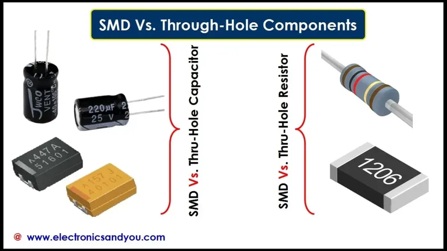
Through-Hole vs SMD
Surface Mount Devices (SMD) and through-hole components represent two distinct approaches to electronic component mounting on printed circuit boards (PCBs). SMD components, designed for surface mounting, contrast sharply with through-hole components, which require leads inserted into plated holes. The choice between these two methodologies significantly impacts manufacturing processes, design constraints, and overall product characteristics.
Prototyping, high-power applications, where mechanical strength is required
Heat Dissipation
Can require thermal considerations for high-power components
Often have better inherent heat dissipation
Frequently Asked Questions About SMD Components
This section addresses common questions regarding Surface Mount Device (SMD) components, providing clear and concise answers to enhance understanding and practical application in electronics.
What exactly are SMD components? SMD components, or Surface Mount Devices, are electronic components designed to be mounted directly onto the surface of a printed circuit board (PCB). Unlike traditional through-hole components, they do not have leads that pass through holes in the PCB, resulting in smaller, more compact assemblies.
What is the fundamental difference between SMT and SMD? Surface Mount Technology (SMT) is the manufacturing method or process of assembling electronic circuits by using SMDs. SMD refers to the components themselves, while SMT refers to the entire process of their assembly onto a PCB. Therefore, SMT is the process that uses SMDs.
How can I effectively identify SMD components? Identifying SMD components involves recognizing markings such as alphanumeric codes, color bands (for resistors), and package shapes. Resources like datasheets, manufacturer websites, and online databases can provide detailed information. For example, a resistor may have a 3-4 digit code or color bands, while an IC will have a part number. Additionally, some components may have a unique geometrical shape.
What is the most common SMD package size and why? Among a wide variety of SMD package sizes, the 0603 and 0805 packages are frequently used due to their balance between small size and ease of handling during assembly. They allow for high component density while still being compatible with automated pick-and-place machines and typical soldering techniques. Smaller sizes like 0402 are becoming increasingly common but require more precise handling.
What are the primary advantages of using SMD components over through-hole components? SMD components offer several advantages, including reduced size and weight, higher component density on PCBs, improved electrical performance due to shorter lead lengths, and cost-effectiveness in mass production. They also lend themselves well to automated assembly processes.
Can SMD components be soldered by hand? Yes, SMD components can be soldered by hand, although it requires more precision and finer tools than through-hole soldering. A fine-tipped soldering iron, solder paste, tweezers, and good lighting are necessary. Proper technique, such as tacking the component with a small amount of solder and then reflowing to make a solid join, is important. Hot air rework stations can also be used for more difficult components.
Where can I find reliable datasheets for SMD components? Reliable datasheets for SMD components can be found on manufacturer websites like Texas Instruments, Analog Devices, and Murata. Additionally, distributor sites such as Digi-Key, Mouser, and Arrow often provide links to datasheets alongside product listings. Always cross-reference datasheets from multiple sources when available.
SMD components are fundamental to the electronics industry, enabling the creation of compact and efficient devices. Understanding their types, sizes, and manufacturing process is essential for anyone involved in electronics design and manufacturing. From the tiniest resistors to complex ICs, these surface-mounted marvels are reshaping our world one component at a time. As technology continues to evolve, mastering SMD components will be even more vital for innovation and progress.