
As environmental regulations like RoHS and REACH tighten, the electronics industry is rapidly transitioning to halogen-free PCB materials. However, replacing traditional FR-4 laminates introduces unique mechanical and thermal challenges. If your design team doesn't adjust its DFM strategy, you risk compromised signal integrity and board failure. This guide breaks down the essential technical adjustments required to master halogen-free fabrication.
Understanding the Material Differences of Halogen-Free Laminates
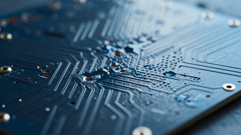
Chemical Transition: Bromine to Phosphorus
Traditional FR-4 laminates utilize brominated flame retardants (BFRs), typically tetrabromobisphenol A (TBBPA), to achieve UL 94 V-0 ratings. While effective, the environmental impact of halogenated compounds has driven the industry toward halogen-free (HF) alternatives. These modern materials primarily employ phosphorus-based chemicals, such as phosphonates or red phosphorus, which facilitate intumescence—the formation of a protective char layer during combustion—rather than relying on gas-phase flame inhibition.
Comparative Analysis of Material Properties
| Parameter | Traditional FR-4 (Brominated) | Halogen-Free (Phosphorus) |
|---|---|---|
| Flame Inhibition Mechanism | Gas Phase (Radical Scavenging) | Condensed Phase (Intumescent Char) |
| Glass Transition (Tg) | Standard (130-150°C) | Higher (150-180°C) |
| Hygroscopicity | Moderate | Higher (Polar nature of phosphorus) |
| Thermal Stability | Lower | Higher (Reduced Z-axis expansion) |
Key Design Implications
- Does phosphorus chemistry affect moisture absorption?
Yes. Phosphorus-based additives tend to be more polar than bromine, which can lead to higher moisture absorption. This requires tighter controls during the baking cycle prior to reflow to prevent delamination or popcorn effects. - How does this impact Z-axis reliability?
Most halogen-free laminates demonstrate superior thermal stability and lower Coefficient of Thermal Expansion (CTE) in the Z-axis, which is highly beneficial for high-layer count boards prone to via barrel cracking. - Are there changes to drilling and surface finish processes?
Due to the higher mineral filler content often added to improve flame retardancy in HF systems, drill wear rates may increase. Designers and fabricators should optimize drill hit counts and entry/backup materials accordingly.
Copper Stack-Up Optimization for Higher Tg Materials
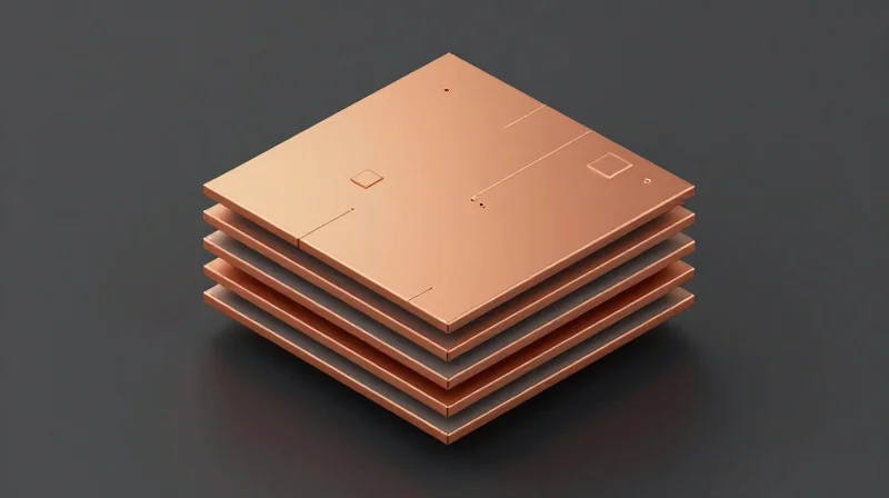
Halogen-free materials typically utilize phosphorus-based flame retardants, which fundamentally alter the resin chemistry. This shift often results in a higher glass transition temperature (Tg) and a more rigid, brittle structure compared to traditional FR-4. Designing for these materials requires a shift toward balanced stack-ups and strategic copper foil distribution to prevent warpage and delamination during high-temperature reflow cycles.
Achieving Stack-Up Symmetry
Because halogen-free laminates exhibit lower z-axis compliance, any inherent asymmetry in the copper stack-up will be magnified during thermal excursions. To maintain dimensional stability, engineers must enforce geometric balance relative to the board's neutral axis.
| Design Element | Standard FR-4 Approach | Halogen-Free Best Practice |
|---|---|---|
| Copper Distribution | Variable density allowed | Balanced copper density per layer |
| Prepreg Selection | Standard flow | High-modulus, low-shrinkage resins |
| Layer Pairing | Non-symmetrical okay | Mirror-image copper planes |
Thermal Stress Mitigation FAQ
- How does higher Tg affect copper peel strength?
Higher Tg materials are generally more brittle; therefore, excessive thermal stress during rework can lead to pad lifting. Ensure consistent copper thickness and avoid sharp internal corners in copper features. - Should I change my copper weight strategy?
Yes. Minimize extreme variations in copper weight between adjacent layers. Using a uniform foil thickness across the internal signal layers helps equalize the CTE expansion rates throughout the stack-up. - Does the laminate modulus impact drilling?
Yes, the increased hardness of halogen-free resins causes faster drill bit wear. Adjust your drill hit counts and use high-speed feed rates to prevent smear and maintain wall integrity.
Copper Pour Guidelines
Implementing a cross-hatch pattern is recommended for large copper planes to reduce the net copper volume while maintaining electrical functionality. This technique helps bridge the CTE gap between the resin and the copper, significantly reducing the probability of corner cracking in multilayer boards.
Refining Drill Parameters for Brittle Substrates
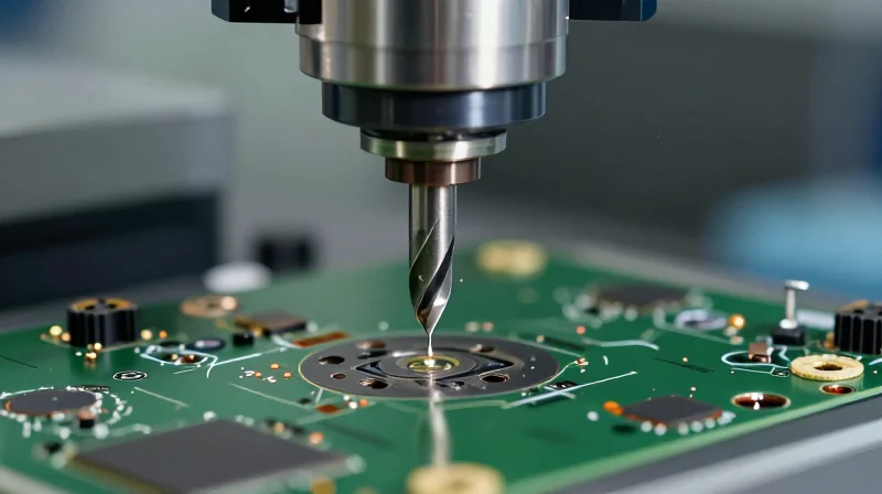
Halogen-free substrates, typically utilizing phosphorus-based flame retardants and higher filler contents, exhibit increased brittleness and hardness compared to traditional FR-4 materials. To avoid thermal shock, resin smearing, and micro-cracking, fabricators must move away from standard drilling recipes and adopt specialized parameters that prioritize low heat generation and controlled debris evacuation.
Key Parameter Adjustments for Brittle Laminates
| Parameter | Standard FR-4 Recommendation | Halogen-Free Best Practice |
|---|---|---|
| Spindle Speed (RPM) | 45k - 60k | 35k - 45k (Lower to reduce friction) |
| Feed Rate (IPM) | 80 - 120 | 50 - 80 (Slower to reduce shock) |
| Retract Rate | High speed | High speed (Critical for heat removal) |
| Drill Geometry | Standard point | High-flute, coated carbide |
Drill Geometry and Bit Maintenance
The use of specialized drill bits is non-negotiable for high-filler content boards. Undercut drill designs assist in improving debris clearance, which is vital as halogen-free resin systems are prone to localized glass transition during the drilling cycle. Furthermore, bit life should be monitored rigorously; as the tool dulls, the increased lateral force induces micro-cracks in the brittle ceramic-filled resin, drastically reducing the board's reliability under thermal cycling.
Frequently Asked Questions on Drilling Optimization
- How does filler content influence drill bit wear?
Mineral fillers increase the abrasiveness of the material, requiring the transition from standard tungsten carbide to diamond-like carbon (DLC) or specialized hardened coatings to maintain hole-wall quality. - Can I use standard entry and back-up materials?
No, you must use high-density aluminum entry foils and phenolic-resin back-up boards to minimize entry burrs and prevent nail-heading during the exit cycle. - What is the primary indicator of incorrect drilling parameters?
The most reliable indicators are resin recession in cross-section analysis and excessive hole-wall roughness during backlighting tests.
Thermal Profile Adjustments for Lamination Cycles

Calibrating Lamination for Halogen-Free Materials
Halogen-free substrates, often utilizing phosphorous-based flame retardants, exhibit different rheological properties compared to standard FR-4. These materials typically possess higher glass transition temperatures (Tg) and lower resin flow characteristics, necessitating a more controlled thermal ramp-up. Failure to adjust the press cycle often results in incomplete polymerization or trapped volatiles, which manifest as delamination during subsequent lead-free reflow processes.
Key Thermal Profile Parameters
| Parameter | Adjustment Strategy | Reasoning |
|---|---|---|
| Ramp Rate | Lower (1.5–2.5°C/min) | Prevents thermal shock and excessive viscosity drops. |
| Pressure Start | Delayed onset | Ensures uniform flow before gelation occurs. |
| Cure Dwell Time | Extended (15–20%) | Compensates for slower cross-linking kinetics. |
Best Practices for DFM and Process Integrity
- How does moisture content affect the lamination cycle?
Halogen-free resins are often more hygroscopic; pre-baking inner layers is essential to remove volatiles that would otherwise cause internal voids during the high-heat pressure cycle. - Why is the pressure application window critical?
Because halogen-free resins have a narrower viscosity window, applying full pressure too early leads to resin starvation, while too late results in poor adhesion between prepreg and copper foils. - How do you verify the cure state?
Utilize Differential Scanning Calorimetry (DSC) to ensure the Tg of the finished laminate matches the material supplier's specifications, indicating a complete cure.
Ultimately, the goal is to align the lamination thermal profile with the specific gelation kinetics of the chosen resin system. Engineers must collaborate closely with material suppliers to obtain viscosity-temperature curves, as standard 'off-the-shelf' cycles are rarely sufficient for high-performance halogen-free substrates.
Maintaining Signal Integrity in High-Speed Designs
Managing Dielectric Variability in Halogen-Free Systems
Halogen-free resins often exhibit slightly higher variations in dielectric constant (Dk) and dissipation factor (Df) compared to traditional brominated materials. To maintain signal integrity, designers must employ rigorous stack-up simulations that account for these material-specific tolerance bands. Utilizing a broad-bandwidth characterization approach during pre-layout modeling ensures that parasitic losses do not compromise the digital signal profile at frequencies exceeding 10 Gbps.
| Parameter | Standard Halogen-Free Tolerance | Mitigation Strategy |
|---|---|---|
| Dk Stability | +/- 0.05 to 0.1 | Use frequency-dependent material models in SI solvers |
| Df Consistency | Within 10% batch-to-batch | Apply trace compensation for skin effect losses |
| Weave Effect | High (Fiber vs. Resin) | Use spread-glass weave styles for uniform distribution |
Design Best Practices for Signal Integrity
- How do I mitigate the glass weave effect?
Specify spread-glass (or open-weave) reinforcements to minimize Dk fluctuations caused by the periodic structure of fiberglass bundles under high-speed traces. - What role does surface roughness play?
Halogen-free substrates often require specific copper profiles; prioritize low-profile (VLP) or hyper-low-profile (HVLP) copper foils to minimize skin-effect-induced signal attenuation. - How should impedance be controlled?
Adjust trace width and spacing based on the supplier-provided Dk values at the target frequency rather than nominal datasheet values, which are often measured at lower frequencies.
In addition to material selection, the interaction between trace geometry and the PCB manufacturing process must be tightly controlled. Etch factor variability in the aggressive chemical environments required for halogen-free laminates can lead to unintended impedance fluctuations. Designers should coordinate with their fabrication partners to establish an optimized etch-compensation library that accounts for the specific resin-to-glass ratio of the selected halogen-free system.
Surface Finish Compatibility and Assembly Considerations
Halogen-free laminates often exhibit higher glass transition temperatures (Tg) and different resin chemistry compared to standard FR-4 materials. Consequently, the interaction between surface finishes and the underlying substrate during multiple reflow cycles becomes a primary DFM concern. Improper finish selection can lead to surface oxidation, intermetallic compound (IMC) brittleness, or pad cratering, particularly when combined with the specific thermal expansion properties of halogen-free systems.
Comparative Analysis of Surface Finishes
| Finish | Thermal Robustness | Compatibility with Halogen-Free | Key DFM Consideration |
|---|---|---|---|
| ENIG | High | Excellent | Risk of black pad if nickel bath is not controlled. |
| Immersion Silver | Moderate | Good | Highly sensitive to sulfur and handling contamination. |
| OSP | Low | Moderate | Limited reflow cycles; verify thermal aging limits. |
| ENEPIG | Very High | Excellent | Superior for mixed technology and wire bonding. |
Key Assembly Considerations
- How does halogen-free chemistry impact solderability?
Halogen-free resins are typically denser and exhibit higher thermal resistance. Ensure your surface finish provides excellent wetting kinetics to compensate for the higher reflow temperatures required for lead-free solder alloys. - Why is ENEPIG preferred for high-reliability applications?
The addition of an electroless palladium layer prevents the migration of copper into the gold, reducing the risk of IMC issues that are exacerbated by the thermal excursions associated with high-Tg halogen-free laminates. - Should OSP be avoided for complex assemblies?
OSP is highly sensitive to heat exposure. If your assembly requires multiple high-temperature reflow cycles or rework, the protective organic layer may degrade, leading to oxidation of the copper pads before final soldering.
Best Practices for DFM Integration
1. Specify Surface Finish Early: Align finish selection with the board's thermal budget. Use ENEPIG for designs undergoing more than three thermal cycles. 2. Avoid Thermal Shock: Ensure the assembly profile accounts for the slower CTE transition of halogen-free materials. 3. Validation: Perform cross-sectional analysis after assembly to check for pad cratering or IMC degradation at the interface between the finish and the copper foil.
Quality Control and Testing Standards

Validated Testing Protocols for Halogen-Free Assemblies
Halogen-free laminate systems exhibit distinct thermal expansion and decomposition characteristics compared to traditional brominated FR-4. Quality control must focus on validating these materials against severe environmental and assembly-induced stresses to prevent delamination, pad lifting, and interlayer micro-cracking.
| Test Standard | Primary Metric | Critical Pass Criteria |
|---|---|---|
| Solder Float (IPC-TM-650) | Thermal Shock Resistance | No delamination after 3 cycles at 288°C |
| Thermal Cycling | Interconnect Integrity | Resistance change < 10% over 1000 cycles |
| T260 / T288 Analysis | Time to Delamination | > 30 minutes at peak temperature |
Key Validation Metrics
- How does the Solder Float test detect defects in halogen-free boards?
The Solder Float test exposes the PCB to extreme molten solder temperatures, forcing rapid expansion of moisture trapped in the dielectric, which exposes potential weaknesses in the resin-to-glass fiber bonding or internal copper-to-dielectric adhesion. - Why is T288 testing critical for this material class?
Halogen-free resins often have higher glass transition temperatures but may be more brittle; T288 testing determines the exact duration a board can withstand reflow temperatures before the chemical structure begins to degrade. - What role does thermal cycling play in DFM?
Thermal cycling validates the coefficient of thermal expansion (CTE) matching between the copper traces and the substrate, ensuring that via barrels do not fatigue under repeated power-on/power-off temperature fluctuations.
Implementing In-Process Controls
Beyond destructive testing, designers must implement cross-sectional analysis on test coupons (A-coupons) for every batch. Monitoring for resin starvation in high-density interconnect (HDI) regions and ensuring that the cure state of the halogen-free polymer is uniform across the entire panel area is paramount to preventing latent field failures.
Transitioning to halogen-free materials is no longer optional—it is a requirement for modern, sustainable electronics. By fine-tuning your DFM rules to account for these material-specific nuances, you can avoid costly design respins and ensure superior reliability in the field. Ready to optimize your next project? Contact our engineering team today for a comprehensive DFM audit and material selection consultation.
