
As we push into the era of 5G and satellite connectivity, the demand for precision has outpaced traditional material capabilities. Engineers are finding that legacy substrate materials like FR-4 are no longer sufficient to handle the rigorous signal integrity requirements of high-frequency applications. This article explores the critical divergence between standard FR-4 and advanced PTFE-based materials, detailing why Teflon has become the indispensable benchmark for modern RF performance.
The Evolution of RF Demands

The Shift in RF Performance Requirements
As modern RF applications migrate toward higher frequency bands—particularly the sub-6 GHz and millimeter-wave (mmWave) spectrums—the margin for signal degradation has narrowed significantly. Traditional FR-4 laminates, while cost-effective for digital basebands, suffer from high dielectric loss (dissipation factor) and instability in the dielectric constant as frequencies climb. These electrical shortcomings translate into excessive signal attenuation and phase shifts that modern antenna arrays, which rely on precise beamforming and high-speed data throughput, can no longer tolerate.
Comparative Performance at High Frequencies
| Parameter | FR-4 (Standard) | PTFE (Advanced) |
|---|---|---|
| Dissipation Factor (Df) | High (0.015 - 0.025) | Ultra-Low (< 0.002) |
| Dielectric Constant (Dk) Stability | Poor (Varies with Frequency) | Excellent (Very Stable) |
| Signal Loss | Significant at > 2 GHz | Negligible at mmWave |
| Thermal Expansion | High/Variable | Low/Controllable |
Critical Challenges in Antenna Design
- Why does dielectric loss matter in antenna arrays?
Higher loss equates to lower antenna gain and efficiency; in high-frequency applications, this manifests as heat and signal weakness, effectively reducing the range and reliability of the wireless link. - How does Dk stability affect beamforming?
Modern phased-array antennas rely on phase synchronization across thousands of elements; if the dielectric constant varies due to material instability, the phase timing becomes erratic, leading to 'beam squint' and poor signal directivity. - Is moisture absorption a factor?
Yes; FR-4 is hygroscopic, meaning it absorbs ambient moisture which drastically alters its electrical properties. PTFE is inherently hydrophobic, providing the long-term reliability required for outdoor RF hardware.
Understanding FR-4: Limitations in the High-Frequency Domain
The Dielectric Barrier: Why FR-4 Fails at Microwave Frequencies
While FR-4 remains the industry standard for digital electronics due to its cost-effectiveness and mechanical rigidity, it is fundamentally ill-suited for high-frequency RF antenna design. The material composition of FR-4—a composite of woven fiberglass cloth and epoxy resin—creates a non-homogeneous dielectric environment. As operating frequencies move into the gigahertz (GHz) range, the dielectric constant (Dk) and loss tangent (Df) of FR-4 become highly unstable, leading to significant signal degradation and unpredictable radiation patterns.
Key Performance Deficiencies
- High Loss Tangent
FR-4 exhibits a high dissipation factor, converting electromagnetic energy into heat rather than facilitating signal propagation, which is catastrophic for antenna efficiency. - Dk Instability
The dielectric constant of FR-4 varies significantly with frequency, temperature, and moisture content, causing uncontrollable impedance shifts in sensitive RF circuits. - Manufacturing Variance
Inconsistent resin-to-glass ratios across the substrate cause variations in performance from batch to batch, making precision tuning of antennas nearly impossible.
| Parameter | FR-4 Standard | Impact on RF Antenna |
|---|---|---|
| Loss Tangent (Df) | 0.015 - 0.025 | High signal attenuation |
| Dk Stability | Poor / Frequency Dependent | Phase velocity errors |
| Thermal Coefficient of Dk | High | Frequency drift in extreme conditions |
Modern RF design requires a stable, predictable dielectric environment to maintain phase accuracy and insertion loss targets. Because FR-4’s composition is inherently lossy and susceptible to environmental changes, it forces engineers to compensate with complex and expensive circuit designs, often failing to reach the performance thresholds required for advanced radar, 5G, and satellite communication systems.
The Science Behind PTFE-Based Materials
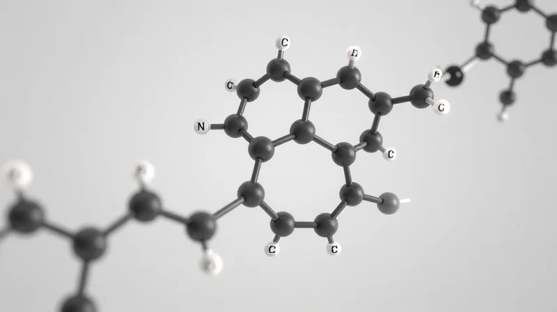
Molecular Foundation of Dielectric Stability
The superiority of Polytetrafluoroethylene (PTFE) in RF design is fundamentally rooted in its highly symmetrical, non-polar carbon-fluorine molecular chain. Unlike the complex fiberglass-reinforced epoxy resins found in standard FR-4, PTFE exhibits an exceptionally low and stable dielectric constant (Dk) across a broad spectrum of temperatures and frequencies. This atomic configuration ensures that the material does not easily polarize under electromagnetic fields, minimizing energy storage within the dielectric and preventing phase distortion in antenna signals.
Key Performance Metrics: PTFE vs. FR-4
| Parameter | PTFE-Based Laminate | Standard FR-4 |
|---|---|---|
| Dissipation Factor (Df) | 0.001 - 0.002 | 0.015 - 0.025 |
| Dielectric Constant (Dk) Stability | Excellent | Poor |
| Temperature Sensitivity | Minimal | High |
| Moisture Absorption | <0.01% | 0.1% - 0.3% |
Mitigating Signal Loss and Thermal Drift
At microwave and millimeter-wave frequencies, the dissipation factor (Df) becomes the primary limiting factor for antenna performance. PTFE provides a significantly lower Df, which translates directly to reduced insertion loss—critical for maintaining high gain and efficiency in phased array antennas. Furthermore, the Thermal Coefficient of Dielectric Constant (TCDk) for PTFE is remarkably low, meaning the electrical path length of the antenna remains constant despite ambient heat generated by high-power operation or harsh environmental conditions.
- Why does PTFE show better signal integrity than FR-4?
PTFE has a lower and more consistent dissipation factor, which limits signal energy loss as heat within the substrate. - How does environmental moisture affect these materials?
PTFE is virtually hydrophobic, preventing water absorption that would otherwise shift the dielectric constant and degrade signal phase in high-frequency designs. - Is PTFE susceptible to thermal degradation?
PTFE exhibits high thermal stability, maintaining its structural and electrical properties far better than the resin systems used in FR-4, which often expand and shift impedance under heat.
Comparative Analysis: Dielectric Constant and Dissipation Factor
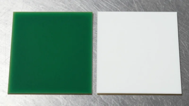
Dielectric Constant (Dk) Stability
The dielectric constant (Dk), or relative permittivity, determines the speed of signal propagation. In RF antenna design, maintaining a consistent Dk across varying frequencies and temperatures is critical for impedance matching and phase stability. FR-4 exhibits a Dk that fluctuates significantly with temperature and frequency, leading to phase errors and impedance mismatches. Conversely, PTFE-based materials provide a remarkably stable Dk, ensuring predictable performance in demanding microwave and millimeter-wave environments.
Dissipation Factor (Df) and Signal Loss
The dissipation factor (Df), or loss tangent, represents the amount of energy lost as heat within the dielectric material. As frequencies climb into the GHz range, the Df of standard FR-4 rises exponentially, causing severe signal attenuation. PTFE materials maintain an ultra-low Df, which minimizes dielectric losses and allows for high-efficiency signal transmission, a non-negotiable requirement for modern high-gain antennas.
| Property | Standard FR-4 | PTFE-based Laminate |
|---|---|---|
| Dielectric Constant (Dk) | 4.4 - 4.8 (Unstable) | 2.1 - 3.0 (Stable) |
| Dissipation Factor (Df) | 0.015 - 0.025 | 0.0005 - 0.002 |
| Thermal Stability | Poor | Excellent |
| Signal Loss | High | Very Low |
Performance Implications for RF Design
- How does Dk variability affect antenna bandwidth?
Fluctuations in Dk shift the resonant frequency of an antenna, narrowing the effective bandwidth and reducing the efficiency of impedance matching networks. - Why does Df matter for long transmission lines?
A high Df causes signal degradation over distance; in complex antenna arrays, this leads to unequal phase distribution and compromised beamforming capabilities. - Can FR-4 be used for 5G applications?
FR-4 is generally unsuitable for modern 5G infrastructure due to excessive signal loss and poor thermal management compared to the superior electrical profiles of PTFE composites.
Thermal Management and Dimensional Stability
Thermal Stability: PTFE vs. FR-4
In RF antenna design, thermal management is not merely a matter of heat dissipation but a critical requirement for maintaining signal integrity. FR-4, a glass-reinforced epoxy laminate, suffers from high coefficients of thermal expansion (CTE) and unstable dielectric constants under varying temperatures. Conversely, PTFE-based materials provide exceptional thermal stability, ensuring that antenna performance remains predictable across extreme environments.
The Impact of Coefficient of Thermal Expansion (CTE)
The mismatch in CTE between copper foil and substrate materials is a primary cause of interconnect failure in microwave PCBs. FR-4 materials typically exhibit a high Z-axis expansion rate, which can lead to barrel cracking in vias during thermal cycling. PTFE laminates are engineered to minimize these mechanical stresses, maintaining reliable electrical connectivity and mechanical integrity where FR-4 would structurally fail.
| Parameter | FR-4 | PTFE Laminate |
|---|---|---|
| Tg (Glass Transition) | 130-180°C | N/A (Stable) |
| CTE Z-Axis (ppm/°C) | 250-300 | 40-60 |
| Thermal Stability | Variable/Degrades | Excellent |
FAQ: Managing Thermal Challenges in RF Design
- Why does FR-4 struggle with thermal cycling?
FR-4 relies on a glass transition temperature (Tg). As temperatures exceed this threshold, the material softens, causing significant dimensional shifts that alter impedance and disrupt circuit performance. - How does PTFE maintain dimensional stability?
PTFE has a naturally low CTE and does not undergo a glass transition, allowing it to maintain precise physical dimensions and consistent dielectric properties even during rapid temperature fluctuations. - Is PTFE the best choice for all high-frequency boards?
While PTFE provides unmatched thermal and dielectric stability, it is costlier than FR-4 and requires specific manufacturing expertise; however, it remains the industry standard for high-performance RF antenna arrays.
Impact on 5G and Satellite Antenna Efficiency
Overcoming the Limitations of FR-4 in High-Frequency Arrays
As 5G and satellite systems move toward higher frequency bands (mmWave and Ka-band), the physical limitations of FR-4 substrates become catastrophic. FR-4 exhibits a high dissipation factor that leads to significant energy absorption as heat rather than propagation as a signal. For antenna arrays, which rely on precise phase synchronization across hundreds of elements, the unstable dielectric constant of FR-4 causes phase errors, resulting in beam steering inaccuracies and reduced antenna gain. PTFE-based materials provide the low-loss environment required to keep these systems efficient.
Performance Metrics: FR-4 vs. PTFE in 5G Infrastructure
| Feature | FR-4 Impact | PTFE Benefit |
|---|---|---|
| Signal Loss | High attenuation at > 6GHz | Minimal loss; ensures signal fidelity |
| Beam Steering | Erratic due to permittivity drift | Stable; precise beam formation |
| Thermal Impact | Degrades at high power loads | High thermal conductivity keeps gain stable |
Impact on Satellite Communication Reliability
Satellite antennas face the harshest environmental extremes, including rapid vacuum-to-sunlight temperature shifts. In these applications, the mechanical rigidity and low dielectric constant of PTFE are non-negotiable. PTFE maintains structural dimensions across temperature swings, ensuring the electrical path length remains constant—an essential requirement for maintaining the tight link budgets found in modern Low Earth Orbit (LEO) satellite constellations.
Frequently Asked Questions regarding 5G Antenna Design
- Why does dielectric loss matter more in 5G than 4G?
5G utilizes shorter wavelengths where every bit of energy loss translates directly to a decrease in the effective range and higher power consumption requirements for the radio unit. - How does PTFE improve beamforming efficiency?
Because PTFE has a tighter tolerance for its dielectric constant, the phase velocity of the RF signal is more predictable, allowing for precise constructive interference in phased-array antennas. - Is the cost of PTFE justified for large-scale 5G deployments?
While more expensive, the reduction in energy waste and the ability to maintain higher data rates per site make PTFE more cost-effective over the operational lifespan of high-capacity 5G networks.
Fabrication Challenges and Design Considerations
The primary challenge in moving to PTFE-based laminates lies in their inherent mechanical softness and chemical inertness. Unlike the rigid, glass-reinforced structure of standard FR-4, PTFE materials require tailored fabrication techniques to maintain structural integrity and minimize signal degradation during the assembly process.
Key Fabrication Nuances
- Drilling and Smear Removal
PTFE is prone to hole wall deformation and 'smear' during drilling. Unlike FR-4, which uses plasma etching, PTFE requires specialized chemical treatment or reactive gas plasma processes to ensure proper copper plating adhesion. - Dimensional Stability
PTFE's coefficient of thermal expansion (CTE) is generally higher than copper, leading to potential layer misalignment during thermal cycling. Design engineers must utilize compensation factors in the artwork to account for the material's movement during lamination. - Surface Preparation
Because PTFE is inherently non-stick, direct copper bonding is challenging. Most manufacturers use modified PTFE substrates with ceramic fillers to enhance bonding characteristics and structural rigidity.
Manufacturing Comparison: FR-4 vs. PTFE
| Feature | FR-4 Processing | PTFE/Ceramic Processing |
|---|---|---|
| Drilling Speed | Standard/Fast | Slow/High Precision |
| Surface Treatment | Standard Oxide | Plasma/Chemical Etching |
| Registration | High Stability | Requires Compensation |
| Cost Impact | Low | High |
Design Considerations for RF Performance
When designing for high-frequency applications, the transition to PTFE demands a holistic view of the circuit layout. Because PTFE materials are often thinner for equivalent impedance performance, parasitic coupling can increase. Designers should focus on maintaining consistent track widths and minimizing abrupt geometric changes to leverage the full bandwidth advantages of advanced PTFE materials.
Future-Proofing Your RF Projects
Strategic Material Selection for Long-Term Viability
Future-proofing RF designs is no longer optional as industry standards push toward higher frequencies and smaller form factors. Engineers must move beyond the limitations of FR-4 by adopting advanced PTFE-based laminates that provide the stable dielectric constant (Dk) and low dissipation factor (Df) necessary for next-generation systems. Choosing the right material stack-up today prevents costly redesigns caused by signal degradation and thermal instability as bandwidth requirements escalate.
| Parameter | FR-4 Capability | PTFE/Advanced Solution |
|---|---|---|
| Signal Loss (Df) | High (>0.018) | Extremely Low (<0.002) |
| Dk Stability | Low Frequency Only | Wide Frequency Range |
| Thermal Reliability | Moderate | Excellent |
| Future-Proofing | Poor for 5G/mmWave | High for 5G/6G |
Key Considerations for Material Transition
- How do I justify the higher cost of PTFE?
View the cost as an investment in lifecycle reliability; PTFE eliminates the recurring expense of field failures and iterative redesigns required when lower-tier substrates fail to meet mounting frequency standards. - Is hybrid board construction a viable strategy?
Yes, utilizing PTFE layers strictly for the high-frequency signal path while maintaining cheaper FR-4 for non-critical circuitry is an industry-standard method to balance performance with budget constraints. - Does thermal expansion dictate material choice?
Absolutely. High-frequency antennas undergo thermal cycling that causes microscopic cracks in standard resins; PTFE's superior dimensional stability ensures consistent performance in harsh environmental conditions.
Technical Best Practices
To ensure your project remains relevant for its intended lifecycle, prioritize materials with a stable Dk over temperature and frequency. Always perform comprehensive EM simulations using accurate material models rather than generic data sheets. By factoring in the coefficient of thermal expansion (CTE) and moisture absorption rates early in the prototyping phase, you mitigate the risk of performance shifts that occur as materials age in the field.
Transitioning to Teflon-based PCB solutions is no longer a luxury but a fundamental necessity for high-performance RF engineering. By prioritizing superior dielectric properties and thermal stability, you can eliminate signal degradation and ensure your next-generation antennas perform at peak capacity. Ready to optimize your hardware for the 5G revolution? Contact our engineering team today to discuss your material stack-up requirements.
