
In the rapidly shifting landscape of high-frequency electronics, selecting the right substrate is the difference between signal integrity and catastrophic loss. As 5G infrastructure and advanced radar systems push frequency boundaries further, engineers continue to rely on time-tested hydrocarbon-ceramic laminates. This article explores why the Rogers 4000 series remains the bedrock of microwave engineering.
The Physics of High-Frequency Signal Loss
The Physics of High-Frequency Signal Loss
At radio frequencies, a PCB substrate is no longer a passive carrier but an active component of the transmission line. Signal loss, or attenuation, occurs primarily through two physical phenomena: conductor loss—caused by skin effect and copper surface roughness—and dielectric loss, governed by the substrate's molecular interaction with electromagnetic fields. As frequencies reach the GHz range, the energy absorbed by the dielectric material increases linearly, making the selection of materials with stable, low-loss properties critical to maintaining signal integrity.
Dk and Df: The Critical Metrics
| Parameter | Definition | Impact on RF Performance |
|---|---|---|
| Dielectric Constant (Dk) | The ratio of the material's permittivity to free space. | Determines signal propagation velocity and impedance stability. |
| Dissipation Factor (Df) | The tangent of the loss angle (tan delta). | Quantifies signal energy lost as heat within the dielectric. |
The dissipation factor (Df) is the most significant indicator of a material's efficiency. In standard FR-4, the polymer chain polarization results in high energy dissipation, which manifests as significant signal attenuation at higher frequencies. Rogers 4350B and 4003C mitigate this by utilizing a ceramic-filled hydrocarbon system that minimizes molecular friction, resulting in a significantly lower Df that remains stable across wide temperature and frequency ranges.
- Why does signal loss increase with frequency?
As frequency rises, the skin effect restricts current to the outer surface of copper conductors, increasing effective resistance, while the dielectric material's dipolar rotation lag creates thermal losses. - What happens when Dk is not stable?
Inconsistent Dk leads to phase distortion and impedance discontinuities, which cause signal reflection and degrade return loss in high-speed circuits.
The Hydrocarbon Advantage: Why Material Composition Matters
The Chemistry of Consistency: Hydrocarbon-Ceramics vs. Legacy Materials
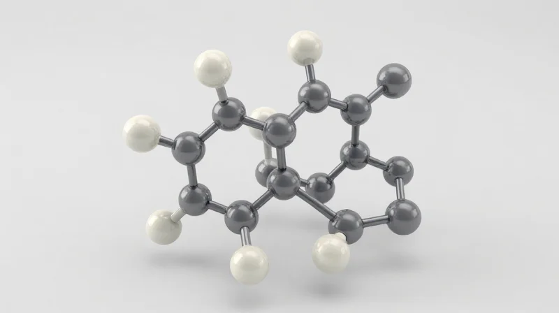
The dominance of the Rogers 4000 series is fundamentally rooted in a proprietary hydrocarbon-ceramic matrix that bridges the gap between traditional rigid board manufacturing and high-performance RF requirements. Unlike PTFE (polytetrafluoroethylene), which is notoriously difficult to process due to its low surface energy and thermal expansion profile, the hydrocarbon-ceramic composition allows for standard FR-4 style fabrication methods while maintaining a stable dielectric constant (Dk) across a broad temperature and frequency spectrum.
Comparative Performance Metrics
| Feature | Hydrocarbon-Ceramic | PTFE-Based | Epoxy/Glass (FR-4) |
|---|---|---|---|
| Dk Stability | Excellent | Good | Poor |
| Thermal Expansion (CTE) | Low/Matched | High | Variable |
| Fabrication Difficulty | Low | Very High | Negligible |
| Moisture Absorption | Very Low | Low | High |
Strategic Advantages in High-Frequency Design
The primary advantage of the 4350B and 4003C materials is their exceptional Coefficient of Thermal Expansion (CTE), particularly in the Z-axis. For complex multilayer boards, high-speed vias are susceptible to cracking or barrel fatigue if the dielectric expands at a significantly different rate than the copper plating. The ceramic filler in these materials tames this expansion, ensuring mechanical integrity under the harsh thermal cycles typical of aerospace, automotive radar, and 5G base station environments.
- Why is the hydrocarbon matrix superior to traditional PTFE?
Hydrocarbon-ceramics offer a more rigid structure that permits standard multilayer lamination, whereas PTFE requires specialized handling and surface treatments to prevent delamination. - How does ceramic filling affect signal integrity?
The ceramic particles provide high dielectric stability and low dissipation factors, which minimizes phase shift and signal dispersion at gigahertz frequencies. - Does moisture absorption impact performance?
Yes; the hydrophobic nature of the hydrocarbon chemistry prevents water ingress, which otherwise causes Dk drifting and signal attenuation in humid operating conditions.
An In-Depth Look at the Rogers 4000 Series
Engineering Excellence in Rogers 4000 Series
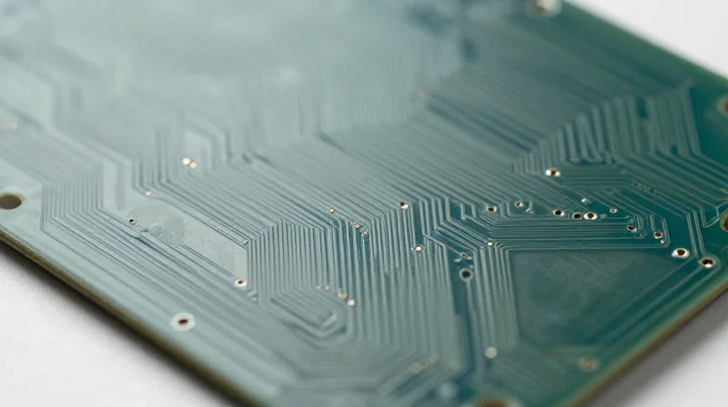
The Rogers 4000 series represents a critical evolution in RF PCB technology, bridging the gap between high-performance ceramic materials and the ease of manufacturing associated with traditional epoxy laminates. The Rogers 4350B and 4003C are specifically engineered to provide consistent electrical characteristics over a wide frequency range, making them the default choice for high-speed digital and RF signal applications where impedance stability is non-negotiable.
Comparative Performance Metrics
| Property | Rogers 4003C | Rogers 4350B |
|---|---|---|
| Dielectric Constant (10GHz) | 3.38 | 3.48 |
| Dissipation Factor (10GHz) | 0.0027 | 0.0037 |
| Glass Transition Temp (Tg) | >280°C | >280°C |
| Flame Rating | UL 94V-0 | UL 94V-0 |
While both materials utilize the same hydrocarbon-ceramic matrix, their key differentiator lies in the inclusion of flame-retardant fillers within the 4350B. This addition allows the 4350B to achieve a UL 94V-0 flammability rating, making it compliant with standard commercial PCB assembly requirements, whereas the 4003C remains a non-brominated, lower-loss alternative primarily suited for specialized high-performance environments where flame retardancy is not a governing specification.
Frequently Asked Questions
- Why is the Rogers 4000 series considered 'process-friendly'?
Unlike PTFE-based materials that require specialized chemical surface treatments, the 4000 series processes similarly to standard FR-4, drastically reducing fabrication lead times and cost. - Which material should I choose for high-frequency low-loss requirements?
If your design constraints allow for non-UL 94V-0 materials, the 4003C is preferred for its lower dissipation factor (Df), which minimizes signal attenuation at microwave frequencies. - Are these materials suitable for multilayer boards?
Yes, both 4350B and 4003C are frequently used in multilayer stackups, though designers must ensure compatibility with the selected prepreg material, typically Rogers 4450F, to maintain impedance continuity.
5G Infrastructure and the Demand for Stable Thermal Management
Thermal Dynamics in 5G Antenna Arrays
5G infrastructure relies on massive MIMO (Multiple Input, Multiple Output) antenna arrays, which concentrate high-frequency RF power into compact, high-density PCB architectures. This density creates significant thermal challenges, as localized heat buildup can degrade signal integrity and mechanical stability. Rogers 4350B and 4003C excel in these environments due to their specific ceramic-filled hydrocarbon formulation, which ensures superior heat dissipation and minimal thermal expansion, protecting delicate surface-mount components from fatigue.
Comparing Thermal Stability Characteristics
| Parameter | Rogers 4350B | Rogers 4003C | Standard FR-4 |
|---|---|---|---|
| Thermal Conductivity (W/m/K) | 0.62 | 0.71 | 0.25 |
| CTE (ppm/°C, X/Y Axis) | 14/16 | 14/17 | 14-17 (unstable) |
| Tg (°C) | >280 | >280 | 130-170 |
The Coefficient of Thermal Expansion (CTE) is perhaps the most critical factor for 5G reliability. Rogers 4350B and 4003C are engineered to match the CTE of copper foil, ensuring that the PCB does not warp or fracture under the rapid temperature cycling associated with high-power 5G signal processing. By providing a low Z-axis expansion profile, these materials prevent plated-through-hole (PTH) cracking, a failure mode common in inferior substrates used in high-frequency thermal environments.
Frequently Asked Questions
- Why is high thermal conductivity critical for 5G PCBs?
5G systems generate significant heat due to high data throughput and signal amplification; effective thermal conductivity allows the substrate to transfer heat away from components to the chassis, preventing thermal runaway. - How does CTE matching improve PCB longevity?
Matching the CTE of the dielectric to the copper circuitry reduces mechanical stress during thermal cycling, which is essential to prevent copper trace delamination and via-barrel cracking in massive MIMO modules. - Can standard FR-4 handle these thermal demands?
No, FR-4 lacks the thermal conductivity and dimensional stability at high temperatures required for RF frequencies; its Tg (glass transition temperature) is significantly lower, leading to rapid performance degradation under 5G operating conditions.
Radar Technology: Precision in Harsh Environments
Radar Technology: Precision in Harsh Environments
Radar systems in automotive and aerospace sectors demand substrates that maintain structural and electrical integrity under extreme thermal cycling and mechanical stress. The Rogers 4000 series, specifically the 4350B and 4003C laminates, remains the industry standard because their hydrocarbon-ceramic matrix prevents the micro-cracking and dielectric shift often seen in traditional substrates when subjected to high-frequency radar operation.
Material Performance in Critical Conditions
In mission-critical radar environments, signal attenuation and phase stability are paramount. The low dissipation factor and stable dielectric constant of these materials ensure that radar resolution remains sharp, even when operating in high-temperature engine compartments or high-altitude aerospace enclosures.
| Feature | Rogers 4350B Benefit | Rogers 4003C Benefit |
|---|---|---|
| Flame Retardance | UL 94V-0 Rated | Non-halogenated |
| Thermal Expansion | Matched to Copper | Matched to Copper |
| High-Frequency Stability | Excellent up to 77GHz | Excellent up to 77GHz |
Frequently Asked Questions
- Why is CTE matching important for radar sensors?
Coefficient of Thermal Expansion (CTE) matching minimizes mechanical stress between the copper traces and the substrate, preventing board delamination and signal degradation during rapid temperature swings. - Can these materials withstand aerospace vibration?
Yes, the robust mechanical modulus of the Rogers 4000 series allows it to resist physical deformation in harsh environments, ensuring consistent electrical contact for critical radar arrays. - Do these materials replace PTFE in radar?
They are often preferred over PTFE because they offer superior rigidity and easier manufacturing processes (similar to FR-4) while maintaining the low-loss electrical characteristics required for high-frequency radar.
Benchmarking Against Traditional FR-4 and Low-Cost Alternatives
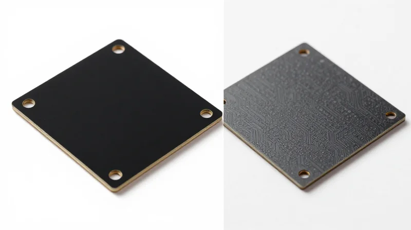
The Limitations of FR-4 at High Frequencies
While FR-4 is the industry standard for low-frequency consumer electronics due to its cost-effectiveness, it fails significantly when pushed into the RF spectrum. The primary deterrent is its high dissipation factor (Df), which results in excessive signal attenuation and power loss as frequencies climb into the gigahertz range. Furthermore, FR-4 suffers from significant dielectric constant (Dk) fluctuations over temperature and frequency, leading to impedance mismatches that degrade signal integrity in critical communications infrastructure.
| Parameter | FR-4 (Standard) | Rogers 4350B/4003C |
|---|---|---|
| Dissipation Factor (Df) | ~0.020 | ~0.0037 |
| Dk Stability | Poor (Varies with temp) | Excellent (Stable) |
| Moisture Absorption | High | Very Low |
| Thermal Reliability | Moderate | High (CTE matched) |
Why Low-Cost Alternatives Often Fail
Engineers are frequently tempted by 'budget' RF laminates that promise performance near the Rogers tier. However, these alternatives often lack the consistent resin-to-glass ratio and precise weave control inherent in 4350B and 4003C. At millimeter-wave frequencies, even minor variances in the glass weave can cause phase skews and unexpected return losses, effectively neutralizing any cost savings gained during the procurement phase due to increased yield loss during manufacturing and final testing.
Frequently Asked Questions
- Can FR-4 be used for any high-frequency design?
FR-4 is generally unsuitable for RF designs above 1 GHz unless the signal paths are extremely short and the performance requirements are lenient. For high-speed data transmission, the losses become prohibitive. - Does the price of Rogers laminates justify the cost?
The higher upfront cost of Rogers 4350B/4003C is typically offset by higher board yields, reduced field failures, and the ability to maintain signal integrity without needing complex compensatory circuitry. - Are there other alternatives for 5G applications?
While newer PTFE-based materials exist, 4350B and 4003C remain the gold standard due to their 'FR-4-like' processability, which keeps fabrication costs lower than exotic specialized laminates.
Manufacturing Considerations and PCB Fabricator Compatibility
Seamless Integration with FR-4 Workflows
Unlike traditional PTFE-based laminates that require specialized chemical treatments, plasma etching, and custom electroless copper processes, Rogers 4350B and 4003C are engineered to be 'fab-friendly.' Their ability to be processed through standard PCB manufacturing lines significantly reduces the barrier to entry for high-frequency designs, minimizing both production cycles and potential manufacturing defects.
Comparison of Fabrication Requirements
| Process Step | FR-4 / Rogers 4000 Series | Standard PTFE Laminates |
|---|---|---|
| Surface Prep | Standard Mechanical/Chemical | Plasma Etching Required |
| Drilling | Standard Carbide Bits | Specialized/Slow Feed Rates |
| Electroless Copper | Standard Process | Proprietary/Complex Chemistries |
| Handling | Robust/Rigid | Dimensionally Unstable/Fragile |
Key Manufacturing Benefits
- Dimensional Stability
The ceramic filler provides excellent dimensional stability during multi-layer lamination, ensuring tight registration for high-density interconnects. - Drilling Efficiency
These materials exhibit consistent wear characteristics similar to FR-4, allowing fabricators to utilize standard drilling protocols without excessive tool breakage. - Multi-layer Compatibility
Their compatibility allows for hybrid stack-ups, where Rogers materials are used for RF signal layers and lower-cost FR-4 for digital control layers.
Strategic Advantages for Supply Chain
Because most major PCB fabricators globally are already equipped to handle Rogers 4000 series materials, designers face fewer limitations regarding vendor selection. This widespread availability mitigates supply chain risks compared to niche high-frequency laminates that require dedicated manufacturing infrastructure or specialized subcontractors. By choosing a material that aligns with established industrial standards, engineers ensure high yield rates and cost-effective scaling from prototype to mass production.
Future-Proofing Your RF Design Strategy
Strategic Material Selection for Long-Term Reliability
As the RF landscape shifts toward 5G, 6G, and sophisticated automotive radar, design engineers must avoid the trap of choosing materials solely on immediate cost. The enduring dominance of the Rogers 4000 series is rooted in a predictable dielectric constant and low dissipation factor, which prevents technical obsolescence as frequency requirements climb. Future-proofing begins with selecting substrates that offer consistent electrical performance across varying temperatures and moisture levels, ensuring that end-user products maintain their specifications over a decade-long service life.
Design Considerations for Future-Proofing
| Parameter | Rogers 4350B | Emerging Standards |
|---|---|---|
| Frequency Stability | Excellent up to 77GHz | Demands even tighter tolerance |
| Thermal Management | High Tg for stability | Advanced heat dissipation required |
| Fabrication | FR-4 compatible | Strict process control needed |
Frequently Asked Questions on RF Substrate Strategy
- Will legacy Rogers materials remain relevant in 6G?
While newer materials are emerging for sub-terahertz applications, Rogers 4350B and 4003C remain the industry benchmark for complex RF front-ends due to their unparalleled track record in reliability and manufacturing ecosystem support. - How does material consistency impact future-proofing?
Consistent dielectric constants (Dk) across production lots prevent costly re-designs when shifting from prototyping to mass production, allowing for modular design upgrades without changing the substrate base. - Is hybrid board construction a viable future-proofing path?
Yes, utilizing a hybrid stack-up where Rogers high-frequency laminates are used in critical RF layers and standard FR-4 in digital/power layers provides a cost-effective route to scaling performance for future high-speed applications.
While the market for RF materials is growing, the Rogers 4000 series continues to offer a perfect balance of performance, manufacturability, and cost-efficiency. By prioritizing high-quality hydrocarbon laminates, engineers can ensure their designs meet the rigorous demands of next-generation connectivity. Contact our engineering team today to discuss selecting the optimal laminate for your high-frequency project.
