
As the telecommunications industry accelerates toward sub-6 GHz and millimeter-wave (mmWave) applications, the physical foundation of our hardware is being pushed to its absolute limits. Traditional design methodologies are no longer enough to support the signal integrity required for ultra-wideband connectivity. In this guide, we analyze why material selection has become the single most important decision for engineers building the wireless backbone of the next decade.
The Paradigm Shift in Wireless Infrastructure

Moving Beyond Legacy Material Limitations
As base station architectures shift toward Massive MIMO and mmWave frequency bands, traditional FR-4 materials are no longer viable. The primary challenges in next-generation connectivity center on signal integrity and thermal dissipation, which drive the adoption of advanced substrates like PTFE-based laminates and hydrocarbon ceramics. Engineers must now prioritize dielectric consistency and low-loss performance over legacy cost-saving material choices.
Material Performance Comparison
| Material Class | Dielectric Constant (Dk) | Dissipation Factor (Df) | Application Focus |
|---|---|---|---|
| Standard FR-4 | 4.5 - 4.8 | 0.015 - 0.020 | Low-frequency legacy systems |
| High-Frequency Laminates | 3.0 - 3.6 | 0.001 - 0.003 | 5G mmWave / Sub-6 GHz |
| Hydrocarbon Ceramics | 3.3 - 3.8 | 0.002 - 0.004 | High-power base station modules |
Critical Engineering Considerations
- Why is Low Loss critical?
As frequencies scale, signal attenuation becomes more pronounced, requiring materials with ultra-low dissipation factors to maintain link budgets. - How does thermal management change?
Next-gen architectures concentrate more power in smaller footprints, necessitating substrates with higher thermal conductivity to prevent degradation of sensitive front-end components. - What is the impact on manufacturing?
Transitioning to low-loss materials often requires specialized fabrication processes, including laser drilling and controlled-impedance etching, to ensure structural reliability.
Limitations of Traditional FR-4 in High-Frequency Environments
Dielectric Loss and Signal Attenuation
The primary drawback of FR-4 in high-frequency applications is its high dissipation factor (Df). As signal frequencies approach the 5G spectrum—specifically the Sub-6 GHz and mmWave bands—the molecular structure of FR-4 causes excessive energy absorption, which is dissipated as heat. This results in significant signal attenuation, drastically reducing the range and reliability of base station transmissions. Unlike specialized laminates, FR-4's inability to maintain low loss profiles over long traces leads to degraded signal integrity, making it unsuitable for high-speed digital and RF pathways.
Comparative Performance: FR-4 vs. High-Frequency Alternatives
| Material Property | Standard FR-4 | High-Frequency Laminate (PTFE/Ceramic) | Impact on 5G |
|---|---|---|---|
| Dissipation Factor (Df) | 0.015 - 0.025 | 0.001 - 0.005 | Signal loss mitigation |
| Dielectric Constant (Dk) Stability | Poor (frequency dependent) | Excellent (consistent) | Impedance control |
| Thermal Conductivity | Low | Moderate to High | Heat management |
Dielectric Constant (Dk) Inconsistency
Effective PCB design at 5G frequencies requires precise impedance control, which is intrinsically tied to the dielectric constant (Dk). FR-4 exhibits a variable Dk that shifts significantly across frequency bands and thermal cycles. In a 5G architecture, this instability leads to impedance mismatches, causing signal reflections and phase distortion. As manufacturers strive to minimize signal noise at high frequencies, the inherent inconsistency of the glass-reinforced epoxy resin in FR-4 prevents the fine-tuning necessary for complex beamforming antenna arrays.
Common Concerns Regarding Legacy Materials
- Does moisture absorption affect FR-4 performance?
Yes. FR-4 is hygroscopic, meaning it absorbs ambient moisture. This moisture changes the Dk of the material, leading to unpredictable signal latency and phase shift, which is unacceptable for precise 5G phase-coherent systems. - Can advanced FR-4 grades solve 5G issues?
While 'High-Tg' or 'Low-Loss' variants of FR-4 exist, they still fail to reach the performance floor required for millimeter-wave frequencies where PTFE-based or hydrocarbon-ceramic materials are mandatory. - How does thermal management limit FR-4?
5G base stations generate intense localized heat. FR-4 has poor thermal conductivity, which can lead to localized delamination or warpage, potentially fracturing critical high-frequency transmission lines.
The Rise of Ceramic-Filled Laminates
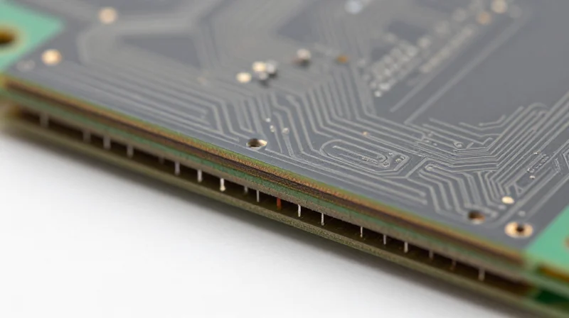
Engineering Superior Performance through Ceramic Integration
As 5G networks push into the mmWave spectrum, traditional organic resin systems fail to maintain the necessary signal integrity. Ceramic-filled laminates address this by incorporating high-dielectric-constant ceramic fillers into PTFE or thermoset hydrocarbon matrices. This composite architecture effectively decouples the thermal expansion coefficient from the signal path, resulting in a substrate that remains rigid and electrically stable even under extreme thermal stress, which is critical for dense base station hardware.
Comparative Analysis: Material Characteristics
| Feature | FR-4 | PTFE-Ceramic Laminate |
|---|---|---|
| Dielectric Loss (Df) @ 20GHz | High (>0.020) | Ultra-Low (<0.002) |
| Thermal Conductivity (W/m·K) | Poor (~0.25) | Excellent (0.6 - 1.2+) |
| Moisture Absorption | Significant | Near-Zero |
| CTE Stability | Variable/High | Low/Matched to Copper |
Critical Advantages for 5G Infrastructure
- Thermal Reliability
The ceramic filler lowers the coefficient of thermal expansion (CTE), preventing delamination and copper barrel cracking during high-power operation in outdoor base stations. - Signal Integrity
Ceramic composites exhibit exceptional dielectric constant (Dk) consistency across frequency and temperature, ensuring phase stability in massive MIMO antenna arrays. - Power Management
The improved thermal conductivity of these materials allows heat to dissipate away from power amplifiers more efficiently, extending component lifespan.
The integration of ceramic-filled materials is no longer a luxury; it is a foundational requirement for 5G. By minimizing dielectric loss and maximizing dimensional stability, these laminates ensure that the next generation of base stations can operate with the high efficiency and reliability mandated by global connectivity standards.
Comparative Analysis: Dielectric Constant and Dissipation Factor
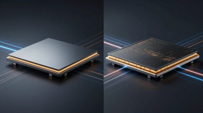
The Role of Dk and Df in High-Frequency Signal Integrity
In the context of 5G and millimeter-wave (mmWave) frequencies, the dielectric constant (Dk) and dissipation factor (Df) are the primary determinants of signal propagation speed and attenuation. As frequencies scale toward 28GHz and beyond, the dielectric constant dictates the phase velocity of the signal, while the dissipation factor represents the energy lost as heat within the dielectric medium itself. For next-generation base stations, minimizing both Dk and Df is essential to prevent signal degradation and maintain the link budget required for massive MIMO antenna arrays.
| Material Category | Typical Dk (10GHz) | Typical Df (10GHz) | Application Suitability |
|---|---|---|---|
| Standard FR-4 | 4.4 - 4.8 | 0.015 - 0.025 | Low-frequency, legacy systems |
| High-Tg Epoxy/PPO | 3.6 - 4.0 | 0.008 - 0.012 | Moderate frequency RF front-ends |
| Ceramic-Filled PTFE | 2.9 - 3.2 | 0.001 - 0.003 | High-performance 5G/mmWave infrastructure |
Key Considerations for Material Selection
- How does Dk impact signal timing?
A stable, low Dk ensures consistent impedance control and propagation delay, which is vital for maintaining phase coherence in massive MIMO antenna systems. - Why is a low Df critical for 5G power efficiency?
A lower Df minimizes dielectric loss, which prevents excessive heat generation and reduces the signal amplification power required, thereby lowering the overall base station power consumption. - Does frequency stability matter for Dk?
Yes, materials with a 'flat' Dk profile across a wide frequency range are necessary to prevent signal distortion when operating across multi-gigahertz 5G bandwidths.
Architecting for the future requires moving beyond traditional substrates. By prioritizing materials with ultralow Df—often leveraging advanced thermoset resins or ceramic-filled fluoropolymers—engineers can overcome the insertion loss hurdles that currently limit signal range in dense urban 5G environments.
Manufacturing Challenges and Design Considerations
Fabrication Challenges with Advanced Substrates
Transitioning from traditional FR-4 to specialized materials involves significant fabrication risks. Advanced low-loss laminates often possess different coefficients of thermal expansion (CTE) and surface roughness characteristics that complicate multi-layer registration, drilling, and copper plating. Precision in trace geometry and via formation is critical, as any deviation in these high-frequency environments can lead to impedance mismatches and catastrophic signal loss.
Design Mitigation Strategies
| Challenge | Design Mitigation Strategy |
|---|---|
| Signal Reflection | Implement precise impedance control via tight stack-up tolerances. |
| Via Stub Resonance | Utilize back-drilling or blind/buried vias to eliminate parasitic capacitance. |
| Thermal Management | Integrate thermally conductive vias and thicker copper planes for heat dissipation. |
| Material Stability | Select low-Dk, low-Df materials with consistent CTE to prevent delamination. |
Common Implementation FAQs
- How does surface roughness affect high-frequency performance?
As frequency increases, the skin effect forces current to flow near the conductor surface; higher copper roughness increases path length and ohmic loss, significantly degrading insertion loss. - Why is CTE mismatch a critical failure point?
During the assembly reflow process, incompatible expansion rates between the laminate and copper foil can cause barrel cracking in vias, leading to intermittent signal failure. - Is hybrid board construction recommended?
Yes, using high-performance laminates for signal-critical layers while keeping cost-effective FR-4 or mid-tier materials for power/ground layers provides an optimal balance between electrical performance and manufacturing cost.
Thermal Management for Next-Gen Architectures
The Thermal Challenge in High-Density Architectures
As 5G base stations move toward massive MIMO (Multiple-Input Multiple-Output) and mmWave frequencies, the concentration of high-power components in smaller footprints creates significant heat dissipation hurdles. Traditional FR-4 materials fail to provide the required thermal transfer, leading to localized 'hot spots' that cause the dielectric constant to drift and compromise signal integrity. Modern architecture requires substrates with enhanced thermal conductivity to ensure reliable long-term operation.
Material Performance Comparison
| Material Type | Thermal Conductivity (W/m·K) | Thermal Stability | Suitability for 5G |
|---|---|---|---|
| Standard FR-4 | 0.25 | Low | Poor |
| PTFE-based Laminates | 0.5 - 0.8 | Moderate | Good |
| Ceramic-filled Thermosets | 1.0 - 2.5 | Excellent | Optimal |
Mitigating Thermal Stress through Advanced Substrates
By incorporating ceramic fillers into laminate resin systems, engineers can significantly improve the thermal conductivity of the PCB stackup. These advanced materials act as a heat-spreading conduit, effectively moving thermal energy away from power amplifiers (PAs) and onto heat sinks or structural chassis components. This reduction in operating temperature directly correlates to lower insertion loss and improved Mean Time Between Failures (MTBF) for base station hardware.
Frequently Asked Questions
- How does thermal conductivity impact signal frequency?
Increased heat causes thermal expansion and dielectric constant variation, which shifts the resonant frequency of filters and antennas; higher conductivity stabilizes these properties. - Are ceramic-filled laminates compatible with standard fabrication?
While they require specialized drilling and plating parameters, modern ceramic-filled thermosets are designed to be compatible with standard multi-layer manufacturing processes. - Why is thermal management critical for mmWave?
At mmWave frequencies, the wavelengths are extremely short, making the circuit sensitive to even microscopic changes in material dimensions caused by thermal expansion.
Future-Proofing Your Hardware Strategy
Strategic Hardware Lifecycle Management
Engineering leaders must move beyond current generation requirements and adopt a forward-looking stance on material procurement. As 5G transitions into 5G-Advanced and 6G concepts, the physical layer—specifically the PCB substrate—remains the primary bottleneck for signal integrity. Future-proofing requires prioritizing low-loss laminates that offer long-term chemical and thermal stability in high-frequency regimes.
| Time Horizon | Hardware Focus | Key Material Requirement |
|---|---|---|
| 1-3 Years | Sub-6GHz Expansion | Reliable FR-4 Alternatives |
| 3-7 Years | mmWave / High-Density | Ultra-Low Loss PTFE/Ceramics |
| 7-10 Years | Integrated 6G Front-End | Nanocomposite/Hybrid Substrates |
Essential Considerations for Scalable Infrastructure
- How do I balance cost and performance?
Avoid over-specifying for immediate needs; instead, adopt a tiered PCB material strategy where high-frequency critical paths use premium laminates, while secondary signal planes utilize more cost-effective, high-Tg resins. - What role does interoperability play?
Next-generation architectures must support open RAN interfaces. Ensure your hardware board files and material specifications are compliant with O-RAN alliance standards to prevent vendor lock-in. - How do we mitigate material obsolescence?
Engage directly with laminate manufacturers to evaluate roadmaps for resin systems. Prioritize materials that have a documented track record of supply chain longevity and are not prone to rapid formulation iteration.
Predictive Design Paradigms
To maintain a competitive edge, design teams should integrate electromagnetic simulation tools early in the CAD process. Relying on digital twins of the PCB assembly allows for the assessment of how material drift—due to environmental aging or thermal cycling—impacts link budget efficiency over a 10-year field lifespan. By investing in robust simulation environments today, engineers can identify material vulnerabilities long before they manifest as network failure points in next-generation base station deployments.
Navigating the complexities of 5G infrastructure requires a deep understanding of material physics and manufacturing precision. By transitioning to advanced laminates, you can ensure your hardware delivers superior signal integrity and reliability. Contact our engineering team today to learn how we can optimize your PCB design for the future of wireless connectivity.
