
The demand for high-speed computing is outpacing the physical limitations of yesterday's hardware. As data centers push toward 400G and 800G connectivity, signal attenuation has become the primary bottleneck. This article examines the shift from standard glass-reinforced epoxies to advanced ultra-low-loss dielectric materials, providing the insights you need to future-proof your network design.
The Evolution of Signal Integrity Requirements

The Shift to High-Speed Serial Links
The rapid advancement of data center networking is primarily driven by the transition from 25G and 56G to 112G and 224G SerDes technologies. As signaling frequencies climb into the multi-gigahertz range, signal integrity (SI) constraints become significantly tighter. Every millimeter of trace length now contributes to substantial insertion loss, making the choice of dielectric substrate the primary determinant in whether a high-speed system will achieve the required Bit Error Rate (BER).
Dielectric Challenges at High Frequency
At 112G PAM4 and beyond, the signal wavelength becomes increasingly short, making the PCB material's dielectric constant (Dk) and dissipation factor (Df) critical parameters. Traditional FR-4-like materials, once the standard for board design, now exhibit unacceptable dielectric loss and signal dispersion at these higher frequencies. Engineering teams must now mitigate skin effect losses and surface roughness-induced impedance variations, leading to the adoption of ultra-low-loss (ULL) laminates with advanced glass weave reinforcement.
| Requirement | Traditional Materials | Ultra-Low-Loss Laminates |
|---|---|---|
| Df (Loss Tangent) | High (0.015 - 0.020) | Very Low (< 0.003) |
| Dk Stability | Frequency Dependent | Stable over Wide Band |
| Target Data Rate | 10G - 25G | 112G - 224G |
Key Considerations for Next-Gen Architectures
- Why is copper foil roughness a factor?
As signals move along the surface of the conductor due to the skin effect, rough copper profiles increase the effective path length and signal attenuation, which is amplified at 112G speeds. - How does glass weave affect signal integrity?
The 'glass weave effect' occurs when the dielectric constant varies due to the physical pattern of the fiberglass reinforcement, causing timing skews that are unacceptable for high-speed differential pairs.
Understanding Dielectric Loss (Df) and Performance
The Physics of Dielectric Loss
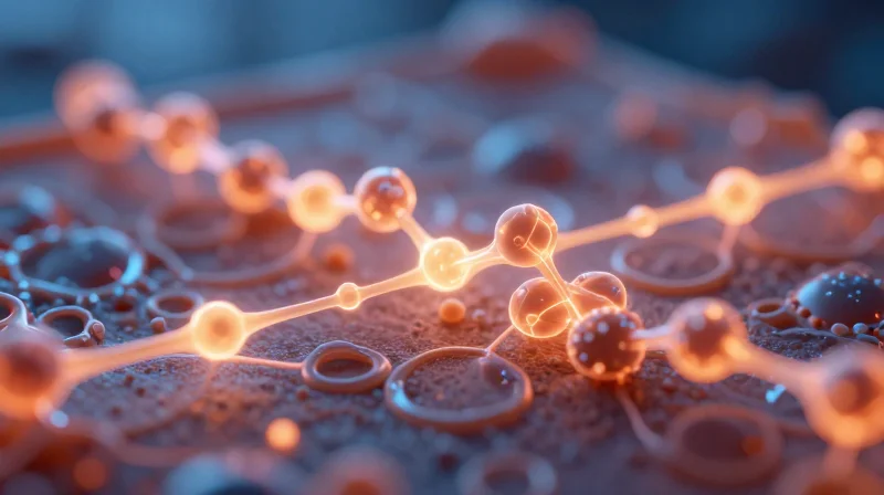
At the molecular level, dielectric loss is a consequence of polar molecules within the substrate resin oscillating in response to rapidly alternating electromagnetic fields. As data rates climb toward 112G and 224G, the frequency of these cycles increases, causing the substrate to behave more like a resistor than a capacitor. This conversion of signal energy into thermal energy manifests as signal attenuation, directly threatening the amplitude and rise time of the transmitted pulse. Lowering the dissipation factor (Df) is therefore essential to preserving signal fidelity across long trace lengths.
Comparing Performance Metrics
| Material Class | Typical Df (@ 10 GHz) | Application Suitability |
|---|---|---|
| Standard FR-4 | 0.015 - 0.020 | Legacy 10G / Low-speed |
| Mid-Loss Laminates | 0.008 - 0.012 | Up to 56G PAM4 |
| Ultra-Low-Loss Laminates | < 0.003 | 112G / 224G SerDes |
FAQ: Dielectric Performance in Modern Networking
- Why does Df become more critical at higher frequencies?
Signal loss due to dielectric dissipation is directly proportional to frequency; as the data rate increases, the loss per inch of transmission line grows significantly, requiring lower-loss materials to maintain the same power budget. - Is Df the only factor affecting signal integrity?
No, while Df is critical for attenuation, Dielectric Constant (Dk) stability, glass weave effects, and conductor surface roughness also play significant roles in managing impedance control and phase jitter. - How do ultra-low-loss laminates differ in material composition?
They utilize specialized ceramic fillers and low-polarity hydrocarbon or PTFE-based resin systems to minimize molecular dipole movement, which inherently reduces the energy lost to heat during high-speed signal propagation.
Limitations of Legacy PCB Materials (FR-4)
For decades, FR-4 (Flame Retardant 4) has been the industry standard for PCB manufacturing, prized for its cost-effectiveness, mechanical robustness, and reliability. However, as data center networking requirements transition toward 112G and 224G SerDes architectures, the fundamental material properties of FR-4 have become a major bottleneck in maintaining signal integrity.
Physics of Failure: Why FR-4 Struggles at High Frequencies
The primary shortcoming of FR-4 is its relatively high dissipation factor (Df). At lower frequencies, dielectric loss is negligible, but at the multi-gigahertz speeds required for today's high-throughput networking, the epoxy resin in FR-4 acts as an inefficient dielectric, absorbing high-frequency signal energy and converting it into heat. Additionally, the woven glass-fiber reinforcement within FR-4 causes a phenomenon known as the 'glass weave effect.' This creates local variations in the dielectric constant (Dk), leading to phase skew in differential pairs, which drastically reduces eye diagram openings.
| Parameter | Typical FR-4 Value | Impact on High-Speed Signaling |
|---|---|---|
| Dissipation Factor (Df) | 0.015 - 0.025 | Excessive signal attenuation and data loss |
| Dielectric Constant (Dk) Stability | Poor / Variable | Increased impedance discontinuities |
| Thermal Management | Low Tg (130-150°C) | Delamination risk under high thermal load |
| Glass Weave Effect | Significant | Phase skew and jitter in differential signals |
Frequently Asked Questions
- Can FR-4 be optimized for high-speed use?
While some 'high-speed' FR-4 variants exist, they typically achieve this by using modified resin systems that still fail to reach the Df levels of ultra-low-loss laminates, rendering them unsuitable for 112G+ applications. - Why does the glass weave effect matter at 224G?
At 224G, the wavelength of the signal is so short that variations in local Dk caused by the glass weave lead to significant timing jitter, making it impossible to reconstruct the data stream accurately. - Is cost the only reason FR-4 is still used?
Yes. Beyond simple board costs, FR-4's manufacturing process is globally standardized, allowing for cheaper, multi-vendor supply chain flexibility compared to proprietary ultra-low-loss materials.
The Advent of Advanced Ultra-Low-Loss Laminates
The Shift Toward Advanced Ultra-Low-Loss Materials
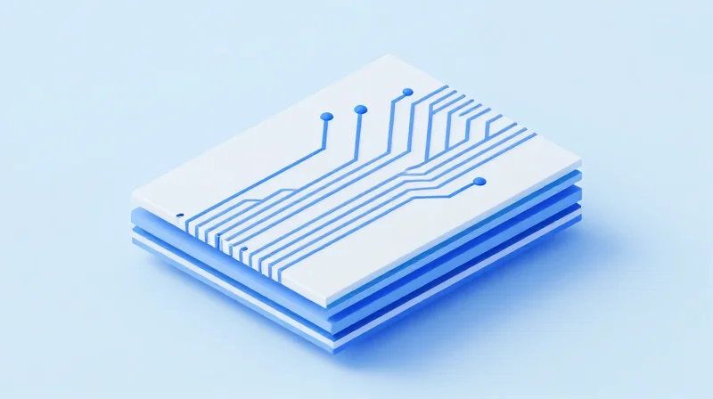
As signal frequencies move toward millimeter-wave territories, traditional epoxy-based substrates fail to maintain signal integrity, leading to severe attenuation. The industry has converged on two primary solutions to meet these challenges: Polytetrafluoroethylene (PTFE)-based composites and ceramic-filled hydrocarbon resins. These materials offer a dielectric constant (Dk) that remains stable across wide frequency ranges and significantly reduced dissipation factors (Df), ensuring that data packets reach their destination with minimal loss or distortion.
Comparing High-Performance Substrate Technologies
| Feature | PTFE-Based Composites | Ceramic-Filled Hydrocarbons |
|---|---|---|
| Dielectric Loss (Df) | Extremely Low (0.001) | Very Low (0.002) |
| Thermal Stability | Excellent | Good |
| Manufacturing Ease | Difficult | Moderate |
| Typical Application | High-frequency RF | High-speed digital routing |
Why Advanced Materials Define Future Infrastructure
Modern high-speed SerDes architectures rely on these advanced laminates to maintain the strict insertion loss budgets demanded by 112G and 224G networking standards. By minimizing the parasitic effects inherent in traditional glass-weave patterns, these materials ensure uniform electrical performance across large-format PCB panels.
- How do ceramic-filled hydrocarbons outperform FR-4?
They provide a lower and more stable dissipation factor while offering better moisture resistance and thermal expansion characteristics compared to standard epoxy-glass resins. - Why is PTFE often the choice for the highest frequency signals?
PTFE possesses the lowest intrinsic dielectric loss of available PCB materials, making it indispensable for maintaining signal integrity at the extreme upper bounds of the frequency spectrum. - Does the transition to these materials increase production costs?
Yes, both material costs and processing complexity increase; however, the improvement in data throughput and reduction in bit error rates (BER) justify the investment for high-end server and switch designs.
Key Performance Metrics for High-Speed Designs
Critical Metrics for High-Speed Signal Integrity
To ensure reliable operation at 112G and 224G PAM4 data rates, engineers must look beyond basic dissipation factors and evaluate metrics that influence the long-term reliability and signal fidelity of the interconnect environment.
- Dk Stability Across Frequency
The variation of Dielectric Constant (Dk) across a broad frequency spectrum dictates impedance control. Ultra-low-loss laminates exhibit minimal Dk roll-off, ensuring that high-frequency harmonics maintain phase coherence. - Thermal Coefficient of Expansion (TCE)
TCE alignment between the dielectric and copper foil is vital to prevent delamination and via fatigue during thermal cycling in high-density rack environments. - Copper Foil Profile
Lower-profile or VLP (Very Low Profile) copper reduces the skin effect losses that occur when current paths are lengthened by the roughness of the copper-dielectric interface.
Material Performance Comparison Matrix
| Metric | Legacy FR-4 | Ultra-Low-Loss Laminate |
|---|---|---|
| Dk Stability (1-50GHz) | High Variance (Unstable) | Low Variance (Stable) |
| Copper Foil Profile | Standard/High Roughness | Very Low Profile (VLP) |
| TCE (ppm/°C) | High (CTE Mismatch) | Low (Engineered Stability) |
FAQ: Reliability and Scaling
- Why is copper roughness a major factor in 224G designs?
At extremely high frequencies, the skin effect forces current to flow near the surface of the copper; surface roughness effectively increases the path length and electrical resistance, leading to significant insertion loss. - How does Dk instability affect timing margins?
Fluctuations in Dk alter the propagation velocity of signals across the board, which can introduce jitter and phase skew in multi-lane high-speed serial links.
Fabrication Challenges and Material Compatibility
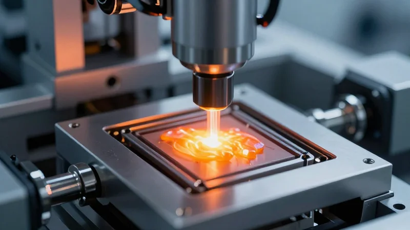
Transitioning from legacy FR-4 to advanced ultra-low-loss laminates is not a drop-in replacement; it demands a fundamental shift in fabrication processes. These advanced materials, often based on PTFE or ceramic-filled hydrocarbons, exhibit unique mechanical and chemical properties that require specialized equipment and modified processing parameters to ensure signal integrity and long-term hardware reliability.
Key Fabrication Challenges
- Dimensional Stability
PTFE-based laminates lack the structural rigidity of glass-reinforced FR-4, leading to material movement during the lamination cycle. This necessitates precise tooling compensation to ensure registration remains within tolerance. - Drilling and Smear Removal
The mechanical properties of ceramic-filled materials accelerate drill bit wear. Furthermore, standard plasma desmear processes used for FR-4 are ineffective on PTFE, requiring specialized plasma gas mixtures (often using hydrogen or argon) to properly prepare via holes for plating. - Surface Preparation and Metallization
Due to their low surface energy, ultra-low-loss materials resist chemical adhesion. Specialized surface treatments, such as chemical etching or aggressive plasma activation, are mandatory to ensure electroless copper achieves sufficient peel strength.
Comparison of Processing Compatibility
| Process Metric | Legacy FR-4 | PTFE/Hydrocarbon Laminates |
|---|---|---|
| Dimensional Stability | High (Predictable) | Low (Requires compensation) |
| Desmear Technique | Permanganate chemical | Specialized Plasma |
| Drill Bit Longevity | Excellent | Poor (Frequent replacement) |
| Copper Bond Strength | Standard | Requires chemical surface treatment |
Material Compatibility and Reliability Risks
The primary risk in adopting ultra-low-loss materials involves the Coefficient of Thermal Expansion (CTE). Misalignment between the laminate and the copper foil or supporting heat sinks can lead to barrel cracking in vias during thermal cycling. Engineers must prioritize material sets with matched CTE profiles to prevent catastrophic failure in dense, high-speed routing environments. Failure to account for these material-specific nuances often results in high initial scrap rates during the prototype phase.
Cost-Benefit Analysis: CAPEX vs. Performance Gains
The Economics of High-Frequency Infrastructure
The transition to ultra-low-loss laminates represents a fundamental shift in capital expenditure (CAPEX) strategy for data center hardware. While traditional FR-4 or standard high-speed epoxy laminates offer lower material costs, they impose a "performance tax" through signal attenuation and increased bit error rates (BER) at speeds exceeding 56Gbps PAM4. Investing in advanced ceramic-filled or PTFE-based materials increases the Bill of Materials (BOM) cost by approximately 30% to 50%, yet these costs are frequently offset by the reduction in required re-transmission logic and improved channel margins.
| Metric | Traditional Laminate | Ultra-Low-Loss Laminate |
|---|---|---|
| Material BOM Cost | Baseline (Low) | High (+30-50%) |
| Signal Attenuation | High @ 112G | Minimal @ 112G |
| Re-transmission Rate | High (Capacity Loss) | Near-Zero (Optimized) |
| Fabrication Complexity | Standard/Low | High (Specialized) |
Quantifying the Performance ROI
The true return on investment (ROI) is found in the optimization of the link budget. In modern data center networking, signal integrity is the primary bottleneck for scalability. Ultra-low-loss materials allow designers to eliminate costly active signal conditioning components such as retimers or complex equalization stages. By reducing the reliance on these components, engineers can simplify the board architecture, potentially offsetting the higher laminate costs through reduced power consumption and improved reliability.
Strategic Considerations
- When is the switch to ultra-low-loss mandatory?
The transition becomes critical when the channel loss budget cannot support the required data rate (e.g., 112G or 224G SerDes) within the physical length constraints of the chassis. - How do operational expenses (OPEX) factor in?
Reduced signal noise leads to lower re-transmission rates, which directly translates to lower power usage and less heat generation, reducing total lifetime cooling costs. - Are there hidden costs in manufacturing?
Yes, high-end materials require specialized drilling, desmear processes, and plating sequences, which can increase throughput time and waste-related overhead in the fabrication facility.
Future Trends: The Road to 1.6T Networking
Navigating the 1.6T Signal Integrity Threshold
As data centers push toward 1.6T speeds, the industry is entering an era where traditional dielectric loss tangents are no longer sufficient. Achieving reliable performance at these frequencies requires a radical reduction in surface roughness and an unprecedented level of Dk stability across wide thermal windows. The road to 1.6T will be defined by the adoption of exotic composite materials and the potential departure from standard copper-clad laminates in favor of ultra-smooth, low-profile alternatives.
Material Evolution Strategy
| Requirement | Current Standard | Next-Gen 1.6T Need |
|---|---|---|
| Dielectric Loss (Df) | 0.002 - 0.003 | <0.001 |
| Copper Profile | VLP (Very Low Profile) | HVLP or Ultra-smooth |
| Thermal Stability | Stable to 100°C | Wide-band consistency |
Key Challenges in 1.6T Infrastructure
- How does signal loss scale at 1.6T?
At 1.6T, transmission losses are dominated by skin effect and dielectric absorption; even minimal surface roughness leads to unacceptable insertion loss, necessitating near-zero profile copper. - Will PCB manufacturing methods change?
Engineers are exploring additive manufacturing and localized laminate treatments to avoid the structural compromises inherent in traditional multilayer bonding processes. - Are there alternatives to standard laminates?
Industry research is shifting toward liquid crystal polymers (LCP) and fluorinated resin systems which offer superior electrical properties at high frequencies, though they present unique thermal management challenges.
The path forward is clear: the physical limits of signal propagation are dictating the material roadmap. Engineers must prioritize extreme material purity to maintain link budgets, as the margins for error at 1.6T continue to shrink toward zero.
Selecting the right material is no longer just a design choice—it is a strategic business decision that dictates the reliability of your entire network ecosystem. By adopting ultra-low-loss dielectric solutions today, you ensure your architecture can support the bandwidth demands of tomorrow. Contact our engineering team today for a comprehensive consultation on material selection for your next high-speed project.
