
The demand for brighter, smaller, and more efficient LEDs has pushed traditional hardware to its breaking point. As power densities climb, engineers are finding that traditional Metal Core Printed Circuit Boards (MCPCBs) often fall short. This article examines the critical transition toward ceramic substrates, providing the technical insight needed to future-proof your next high-power lighting project.
The Evolution of LED Power Density
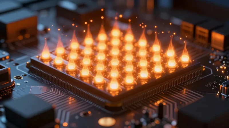
The Escalating Demand for Thermal Dissipation
As LED technology advances toward smaller footprints and higher lumen output, the power density—measured in watts per square millimeter—has increased exponentially. This miniaturization creates a significant thermal bottleneck. Standard cooling methods are no longer sufficient to maintain junction temperatures within optimal ranges, leading to rapid lumen depreciation and premature device failure. Consequently, the industry is transitioning away from conventional thermal management strategies toward materials that offer superior heat conductivity and electrical insulation.
Comparative Thermal Performance Metrics
| Material Property | Metal Core PCB (Al) | Ceramic (AlN) |
|---|---|---|
| Thermal Conductivity (W/m·K) | 1.0 - 3.0 (Dielectric) | 170 - 230 |
| Thermal Expansion (CTE) | High (Mismatch risk) | Low (Matches Si/LED) |
| Electrical Isolation | Dependent on dielectric | Inherently insulating |
Key Challenges in High-Density LED Packaging
- What is the primary limitation of Metal Core PCBs (MCPCBs) in high-power applications?
The weakest link in an MCPCB is the dielectric layer between the copper circuit and the metal base; its relatively low thermal conductivity creates a significant barrier to heat transfer. - Why is Coefficient of Thermal Expansion (CTE) critical for LED longevity?
A mismatch between the LED die and the substrate causes mechanical stress during thermal cycling, which leads to solder joint cracking and permanent optical degradation. - How do ceramic substrates resolve these density challenges?
Ceramics like Aluminum Nitride provide a high-thermal-conductivity path directly under the die, eliminating the need for an insulating dielectric layer and allowing for vastly improved heat dissipation.
Understanding the Limitations of MCPCBs
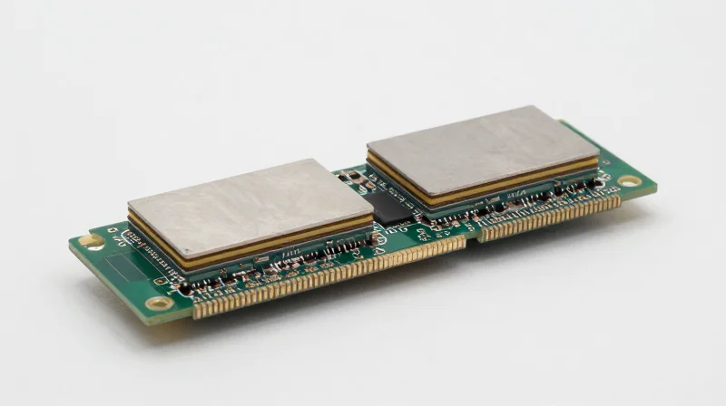
The Dielectric Layer Bottleneck
The primary limitation of traditional MCPCBs lies in the thermal interface between the copper circuit layer and the aluminum or copper base. This interface relies on a thin dielectric layer, typically composed of polymer-based materials filled with thermally conductive ceramic particles. While these materials improve heat transfer compared to standard FR4, they possess significant thermal resistance compared to the base metal, creating a 'bottleneck' effect that prevents efficient heat dissipation from high-power LED junctions.
Key Performance Constraints
- Thermal Conductivity Limits
Most organic dielectrics provide thermal conductivity between 1-3 W/mK, which is insufficient for next-generation, high-lumen density illumination. - Coefficient of Thermal Expansion (CTE) Mismatch
The disparity in expansion rates between the organic dielectric, copper foil, and metal core can lead to mechanical stress and delamination during high-frequency thermal cycling. - Electrical Breakdown Strength
Polymer-based dielectrics are prone to degradation over time when subjected to extreme heat and high voltages, reducing the long-term reliability of the insulation barrier.
Comparison of Thermal Impedance
| Material Property | MCPCB (Polymer-Based) | Ceramic (AlN/Al2O3) |
|---|---|---|
| Thermal Conductivity (W/mK) | 1.0 - 3.0 | 20 - 180+ |
| Dielectric Reliability | Subject to aging/delamination | Inherent stability |
| Operating Temperature | Limited by organic binder | Capable of extreme heat |
Under extreme thermal loads, the failure of the organic binder within the dielectric layer is often the point of system collapse. Because polymers have lower melting points and higher thermal resistance than inorganic ceramic substrates, MCPCBs effectively cap the maximum power density that an LED system can maintain without experiencing premature luminous flux degradation or complete component failure.
Ceramic Substrates: The New Industry Gold Standard
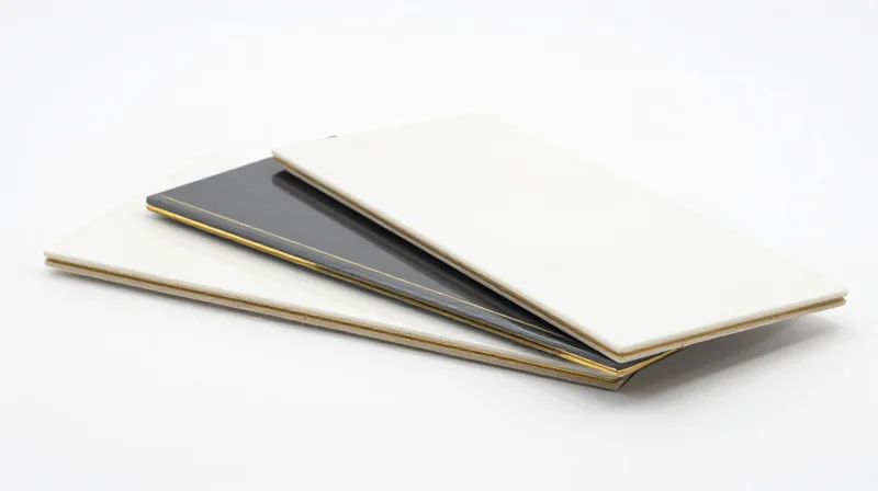
Ceramic Substrates: The New Industry Gold Standard
As LED power densities climb, traditional Metal Core PCBs (MCPCBs) reach a physical limit imposed by the thermal resistance of their dielectric layers. Ceramic substrates eliminate this bottleneck entirely by providing a monolithic, thermally conductive structure that acts as both the circuit carrier and the primary heat spreader. By removing the need for a non-conductive polymer layer, ceramic materials ensure direct thermal paths, enabling LEDs to operate at significantly higher currents without sacrificing lifespan or color stability.
Core Ceramic Material Profiles
| Material | Thermal Conductivity (W/mK) | Key Advantage |
|---|---|---|
| Alumina (Al2O3) | 25 - 30 | Cost-effective, standard reliability |
| Aluminum Nitride (AlN) | 170 - 230 | Extreme thermal management |
| Silicon Nitride (Si3N4) | 60 - 90 | High fracture toughness and thermal cycling |
The choice between these ceramics depends on the specific thermal-mechanical demands of the lighting architecture. Alumina remains the most ubiquitous choice for general lighting, while Aluminum Nitride is favored for high-brightness automotive and industrial applications where heat flux is at its maximum. Silicon Nitride, while slightly less conductive than AlN, provides mechanical robustness in environments subject to harsh vibration or extreme rapid thermal cycling.
Frequently Asked Questions
- Why is the dielectric layer of an MCPCB a disadvantage?
The dielectric layer acts as an insulating thermal barrier; even with fillers, its thermal conductivity is significantly lower than that of the base metal, creating a 'thermal choke' point. - Do ceramic substrates require a specialized manufacturing process?
Yes, they typically employ Direct Bond Copper (DBC) or Thick Film technology, which bonds copper directly to the ceramic, ensuring superior mechanical adhesion and lower electrical resistance. - Are ceramic substrates brittle?
While ceramics possess lower tensile strength than aluminum, modern compositions like Silicon Nitride offer improved fracture toughness, making them highly resistant to the mechanical stresses inherent in LED modules.
Comparative Material Properties: Thermal Conductivity and Beyond
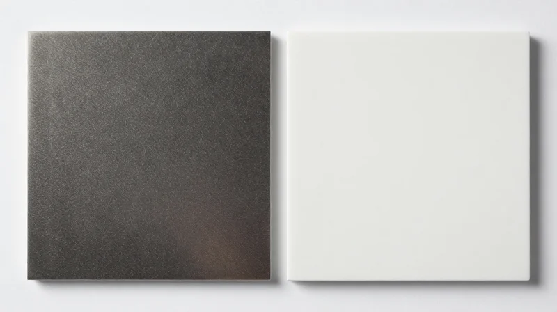
Comparative Material Properties: Thermal Conductivity and Beyond
Selecting the optimal substrate hinges on balancing thermal conductivity, dielectric strength, and Coefficient of Thermal Expansion (CTE) matching. While MCPCBs rely on a thin polymer dielectric layer that acts as a thermal barrier, ceramic substrates offer monolithic thermal paths that drastically reduce junction-to-ambient resistance.
| Property | MCPCB (Al) | Alumina (Al2O3) | Aluminum Nitride (AlN) |
|---|---|---|---|
| Thermal Conductivity (W/mK) | 1.0 - 5.0 (dielectric limited) | 20 - 30 | 170 - 230 |
| Dielectric Strength (kV/mm) | 3 - 5 | > 15 | > 15 |
| CTE (ppm/°C) | 22 - 24 (Base) | 6.5 - 7.5 | 4.5 - 5.0 |
Technical Implications of Material Selection
The primary disadvantage of the MCPCB is the dielectric layer. Even with high-fill thermally conductive resins, the dielectric remains a significant bottleneck, typically exhibiting thermal resistance several orders of magnitude higher than the metal base. Conversely, ceramic substrates such as Aluminum Nitride act as both the dielectric and the heat spreader. Because ceramics are rigid and possess lower CTE values, they mitigate mechanical stress on solder joints during rapid thermal cycling, a common failure mode in high-density LED arrays.
- How does dielectric strength affect reliability?
Ceramic substrates provide superior dielectric strength, allowing for thinner board architectures without risk of electrical breakdown, which further decreases thermal resistance. - Why is CTE matching critical for LEDs?
LED chips are typically made of sapphire or silicon carbide with low CTE; ceramic substrates (low CTE) match the chip much better than metal (high CTE), preventing solder joint fatigue. - Can MCPCBs ever outperform ceramics?
MCPCBs remain the cost-effective choice for low-to-mid power applications where the thermal path efficiency of ceramics provides diminishing returns relative to the increased material cost.
Reliability and Longevity in Harsh Environments
Thermal Cycling and Structural Integrity
In demanding industrial, automotive, and aerospace lighting environments, LEDs are subject to constant thermal cycling—the rapid expansion and contraction caused by power fluctuations. Metal Core PCBs (MCPCBs) rely on a thin polymer-based dielectric layer to electrically insulate the circuitry from the metal base. Over time, the differing Coefficients of Thermal Expansion (CTE) between the copper traces, the organic dielectric, and the metal core induce mechanical fatigue, leading to delamination or dielectric cracking. Ceramic substrates, conversely, are inherently monolithic and inorganic. By utilizing materials like Aluminum Nitride or Alumina, the substrate acts as a unified heat-spreading platform with a CTE closely matched to the semiconductor chip itself, virtually eliminating the risk of interfacial separation under extreme thermal stress.
Failure Mode Comparison
| Failure Metric | MCPCB Performance | Ceramic Substrate Performance |
|---|---|---|
| Thermal Fatigue | High (Dielectric cracking) | Low (Monolithic structure) |
| Delamination Risk | Significant due to organic layers | Minimal (Fused interfaces) |
| Expansion Uniformity | Poor (CTE mismatch) | Excellent (Close CTE match) |
Frequently Asked Questions
- Why do organic dielectrics in MCPCBs fail first?
Organic resins used in MCPCB dielectrics have lower thermal degradation thresholds and higher CTE values compared to metals, causing them to shear away from the substrate during repeated heat cycling. - Do ceramic substrates experience stress-related warping?
Because ceramics are rigid and possess high Young’s modulus values, they maintain geometric stability far better than metal-clad boards, preventing the micro-warping that often breaks delicate solder joints in harsh conditions. - How does ceramic material choice impact environmental resilience?
Aluminum Nitride offers the highest thermal conductivity and lowest CTE, making it the superior choice for high-power density applications where thermal shock is frequent and severe.
Design Considerations for Ceramic Implementation
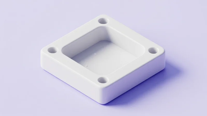
Engineers transitioning from Metal Core PCBs (MCPCBs) to ceramic substrates must pivot from a 'bend-tolerant' design philosophy to one centered on structural integrity and vibration dampening. Because ceramic materials—such as Alumina (Al2O3) or Aluminum Nitride (AlN)—lack the ductility of aluminum or copper backing, the primary design challenges involve managing mechanical stress, optimizing mounting tolerances, and ensuring reliable interconnects.
Mechanical Integration and Handling
The susceptibility of ceramic to micro-cracking necessitates specific board-level design interventions. Unlike MCPCBs, which can absorb minor mechanical shocks via material deformation, ceramics will fracture under localized stress points. Designers must ensure that mounting hardware does not induce bending moments into the substrate.
| Parameter | MCPCB Design | Ceramic Design |
|---|---|---|
| Mounting Approach | Torque-tolerant | Stress-isolation required |
| Handling Precautions | Standard ESD/Physical | High shock/vibration sensitivity |
| Coefficient of Thermal Expansion (CTE) | Requires buffer layers | Matches LED chips closely |
Best Practices for Assembly
- Optimizing Interconnects
Use flexible wire bonding or gold-plated soft solder joints to minimize stress transfer from the PCB to the LED component. - Thermal Interface Material (TIM) Selection
Utilize low-modulus TIMs to accommodate minute expansions, preventing the ceramic from cracking during rapid thermal cycling. - Mechanical Support
Implement rigid, flat base plates or custom housing recesses to support the entire surface area of the ceramic, avoiding unsupported spans.
Frequently Asked Questions
- Can I use standard clamping methods with ceramics?
No, traditional heavy-pressure clamps often cause cracking. Use spring-loaded clips or controlled-torque fasteners with thermal pads to distribute pressure evenly. - How does ceramic hardness affect PCB thickness?
Ceramics are typically thinner than MCPCBs due to their superior dielectric properties, allowing for smaller form factors without sacrificing thermal performance.
Cost-Benefit Analysis for High-Performance Applications
The Economic Trade-Off: Upfront Investment vs. Operational Value
While ceramic substrates, such as Alumina (Al2O3) or Aluminum Nitride (AlN), command a higher unit cost compared to traditional MCPCBs, the economic justification lies in the total cost of ownership. By eliminating the need for bulky heat sinks and external cooling infrastructure, ceramic designs often yield a lower net system cost, particularly in high-density lighting applications where performance requirements exceed the thermal saturation point of metal-clad boards.
| Feature | Metal Core PCB | Ceramic Substrate |
|---|---|---|
| Unit Material Cost | Low | High |
| System Miniaturization | Moderate | Excellent |
| Long-term Reliability | Standard | Superior |
| Heat Sink Dependency | High | Low |
Long-Term Reliability and Maintenance Savings
The reliability premium of ceramic substrates significantly reduces maintenance expenditure. MCPCBs frequently suffer from bond-line degradation between the dielectric layer and the metal base under high thermal stress. In contrast, the monolithic structure of ceramic substrates avoids these interface failures, extending the service life of high-performance LED luminaires and drastically reducing the frequency of component replacement in inaccessible or critical environments.
Common Economic Considerations for Implementation
- Does the higher cost of ceramics impact product time-to-market?
Initially, specialized handling for ceramic brittleness may increase assembly time, but the reduction in board-level thermal management design complexity often accelerates the overall prototyping phase. - At what threshold does ceramic become more cost-effective?
Ceramics generally reach parity when system miniaturization targets are met or when the application requires high thermal stability that MCPCBs cannot provide without adding costly active cooling solutions. - Are there secondary savings in logistics?
Yes, because ceramic substrates are inherently lighter and allow for smaller, more efficient fixtures, organizations can realize substantial savings in shipping, installation labor, and warehousing costs.
Market Predictions for Thermal Management Hardware

The Five-Year Market Trajectory
Over the next five years, the thermal management landscape for LED technology is expected to favor ceramic substrates, driven by the proliferation of high-density packaging and extreme-environment lighting. While Metal Core PCBs (MCPCBs) will retain dominance in cost-sensitive, general illumination sectors, the rapid advancement of electric vehicles (EVs), industrial UV-C curing, and aerospace lighting will necessitate the superior thermal conductivity and electrical isolation properties offered by materials like Aluminum Nitride (AlN) and Alumina (Al2O3).
| Market Metric | Metal Core PCB (MCPCB) | Ceramic Substrates |
|---|---|---|
| Growth Forecast | Stable/Moderate | High/Aggressive |
| Primary Application | General Lighting/Retail | Automotive/Medical/Defense |
| Thermal Conductivity | Limited by Dielectric | Excellent/Intrinsic |
Supply Chain and Standardization Trends
Supply chain maturity for ceramic manufacturing is currently undergoing a transformative phase. As industrial demand grows, economies of scale are beginning to lower the unit price of ceramic substrates, narrowing the gap with traditional metal-clad options. Furthermore, we anticipate the emergence of new international standards focusing on 'thermal interface consistency,' which will likely penalize traditional MCPCBs due to their inherent dielectric bond-line variability.
- Will ceramic substrates replace MCPCBs entirely?
No. MCPCBs remain the standard for low-to-mid power applications where cost efficiency is paramount; ceramics will occupy the high-performance tier where thermal headroom is non-negotiable. - What role does miniaturization play?
Ceramic's superior heat dissipation allows for tighter component spacing on the board, enabling smaller footprints that are essential for the next generation of compact, high-lumen density LED arrays. - How does sustainability influence these trends?
Ceramics offer better chemical stability and longevity in harsh conditions, reducing the frequency of replacement and material waste, which aligns with emerging ESG requirements in industrial electronics.
Transitioning to ceramic substrates is no longer a luxury; it is a necessity for the next generation of high-power LED arrays. While the design shift requires careful planning, the gains in thermal efficiency and device lifespan are undeniable. Ready to elevate your hardware? Contact our engineering team today for a consultation on selecting the optimal substrate for your specific application.
