
As consumer expectations for smaller, more powerful devices skyrocket, the physical limitations of traditional rigid printed circuit boards have become a major bottleneck. Engineers are now turning to rigid-flex technologies to solve the 'space-versus-functionality' dilemma, creating a new paradigm for high-performance interconnects in compact hardware.
The Evolution of Form Factors: Why Rigid Boards are Stalling
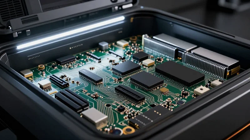
For decades, rigid printed circuit boards (PCBs) paired with wire harnesses served as the foundational architecture for electronics. However, as product profiles shrink to accommodate increased battery capacity and sophisticated sensors, the physical limitations of rigid assemblies have become a bottleneck. Traditional boards struggle to balance spatial density with reliability, particularly where interconnects are forced into cramped, high-vibration, or non-linear environments.
The Limitations of Legacy Rigid Assemblies
The reliance on rigid boards connected by manual cabling introduces significant points of failure. Every connector pair and solder joint represents a potential weak point for signal integrity and mechanical fatigue. In high-density applications, the sheer volume consumed by bulky connectors and physical cabling prevents further miniaturization, effectively stalling innovation in wearables, medical implants, and compact drone platforms.
| Feature | Rigid Assembly + Harness | Rigid-Flex PCB |
|---|---|---|
| Space Efficiency | Low (High cable volume) | High (Integrated footprint) |
| Reliability | Variable (Connector failure) | Superior (Monolithic connection) |
| Assembly Speed | Slow (Manual labor) | Fast (Automated soldering) |
| Vibration Resistance | Poor (Connectors loosen) | Excellent (Flexible transitions) |
Common Industry Challenges
- Why is the rigid-connector model failing?
Modern electronics require dynamic movement and tighter housing; rigid assemblies occupy too much volume and create mechanical stress at the transition point between the board and the cable. - Does weight play a factor in the industry shift?
Yes, eliminating heavy connectors, thicker copper wiring, and bulkier housings allows for significantly lower weight, which is critical for portable and aerospace-grade applications. - How does rigid-flex mitigate signal interference?
By replacing high-resistance physical connections with trace-to-trace continuity across flexible polyimide layers, impedance mismatches and crosstalk are substantially reduced.
Understanding Rigid-Flex PCB Architecture
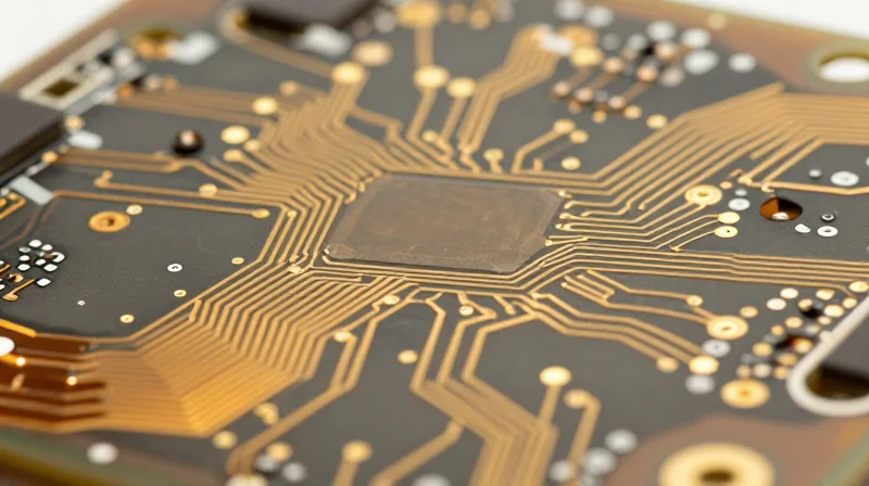
Structural Integration of Materials
Rigid-flex architecture is defined by the hybrid integration of high-performance rigid substrates, such as FR-4 or high-speed laminates, and flexible polyimide film layers. Unlike traditional assemblies that rely on connectors and cables, a rigid-flex design creates a monolithic, electrically unified structure. The flexible sections are chemically bonded into the rigid stacks, allowing the entire assembly to fold or bend during the installation process while maintaining consistent electrical integrity.
Key Architectural Advantages
- Interconnect Reliability
By eliminating mechanical connectors and manual cabling, rigid-flex designs remove the most common failure points in complex electronics. - Three-Dimensional Routing
The architecture allows for complex board shapes that fold into tight housing geometries, maximizing vertical space utilization. - Signal Integrity
Direct circuitry reduces the path length and prevents signal degradation often caused by high-impedance connector interfaces.
| Feature | Traditional Rigid Assembly | Rigid-Flex Architecture |
|---|---|---|
| Connectivity | Cables and Connectors | Integrated Monolithic Circuits |
| Space Efficiency | Low (limited by connectors) | High (optimized for folding) |
| Assembly Complexity | High (manual assembly required) | Low (single-part installation) |
| Failure Points | Mechanical fatigue at joints | Minimal (integrated connections) |
Critical Design Considerations
Designing for rigid-flex requires precise management of the 'bend radius' to avoid mechanical stress on conductive traces. Engineers must ensure that trace widths in the flexible regions are specifically calculated to accommodate repeated mechanical flexure without fatigue. Furthermore, the transition area—where the rigid material meets the flex section—must be engineered with a proper 'fillet' and layer-stackup design to prevent delamination during the thermal cycling inherent in operational environments.
Performance Metrics: Rigid-Flex vs. Traditional Assemblies
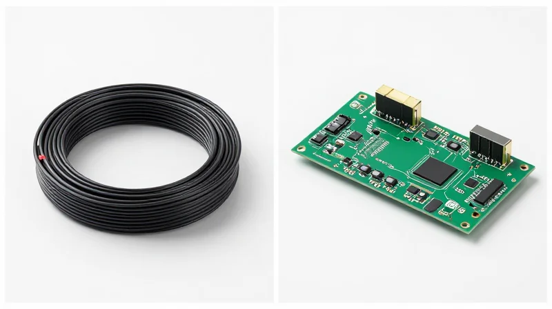
Comparative Performance Analysis
Rigid-flex PCBs offer a paradigm shift in performance by eliminating the parasitic effects associated with traditional connectors, bulky cabling, and mechanical joints found in standard rigid-to-rigid assemblies.
| Metric | Traditional Rigid Assembly | High-Precision Rigid-Flex |
|---|---|---|
| Signal Integrity | Variable; subject to connector-induced noise and impedance discontinuities. | High; minimizes interconnect length and eliminates unreliable mechanical mating. |
| Thermal Management | Limited by interface resistance between boards and connectors. | Superior; integrated copper paths allow efficient heat dissipation across the circuit. |
| Connection Reliability | Prone to contact oxidation, vibration-related loosening, and wear. | Excellent; monolithic construction prevents common mechanical failure points. |
Signal Integrity and Thermal Efficiency
In high-speed data transmission, every connector acts as a potential source of electromagnetic interference and signal degradation. By replacing multi-board connectors with flexible polyimide transitions, rigid-flex designs maintain consistent controlled impedance across the entire assembly. Furthermore, the removal of heavy cable bundles facilitates better airflow and allows copper traces to extend seamlessly across the flexible segments, serving as thermal conduits that help regulate localized heating in space-constrained environments.
Frequently Asked Questions
- How does rigid-flex improve signal integrity over wire harnesses?
Rigid-flex designs remove high-resistance connectors and erratic wire routing, allowing for precise, stable impedance control and lower insertion loss. - Is thermal management inherently better in rigid-flex?
Yes. Rigid-flex allows for continuous copper planes that distribute heat away from dense components more effectively than fragmented, connector-based rigid assemblies. - Do vibrations affect rigid-flex more than rigid assemblies?
No; in fact, the lack of mechanical connectors makes rigid-flex significantly more resistant to vibration-induced failures, as there are no loose parts or contact points to degrade.
The Rise of TWS Interconnects

Engineering for Extreme Miniaturization
The evolution of TWS earbuds and smart wearables represents one of the most aggressive challenges in modern PCB engineering. Unlike legacy consumer electronics, TWS devices require a multi-dimensional approach to layout, where the internal volume is dominated by battery capacity, leaving minimal overhead for interconnect systems. Traditional rigid boards and bulky connector-based harnesses are fundamentally incompatible with these form factors, as they consume excessive z-height and introduce mechanical failure points at high-vibration sites.
Comparative Efficiency in TWS Applications
| Feature | Traditional Rigid Assembly | Rigid-Flex PCB |
|---|---|---|
| Spatial Efficiency | Low (High volume/connector overhead) | High (Contoured, 3D integration) |
| Weight Profile | High (Rigid substrate + wires) | Ultra-Low (Polyimide flex base) |
| Signal Path | Discontinuous (Connector bottlenecks) | Continuous (Eliminates inter-board connectors) |
Optimizing Signal Density and Reliability
Rigid-flex technology allows engineers to fold the circuitry within the product casing, effectively using the internal air gap as structural volume. In TWS, this is critical for housing Bluetooth antennas and specialized capacitive touch sensors. By removing physical connectors, designers gain significant improvements in signal integrity; each connector interface is a potential source of impedance mismatch and signal loss, which are unacceptable in high-bandwidth wireless applications. The monolith nature of rigid-flex circuits ensures a consistent return path and lower electromagnetic interference (EMI).
Frequently Asked Questions
- Why is rigid-flex preferred over rigid boards with wire harnesses in TWS?
Wire harnesses are bulky and difficult to automate in assembly. Rigid-flex circuits replace these with thin, flexible polyimide layers that fold into tight spaces, significantly reducing the total device volume. - Does the removal of connectors affect long-term reliability?
Yes, it enhances it. Connectors are common failure points in mobile devices due to vibration, thermal cycling, or shock. A rigid-flex design integrates the interconnection into the substrate, eliminating these weak links. - How does rigid-flex help with antenna performance?
The ability to position flex sections precisely against the internal shell of the device allows for better antenna placement, optimizing radiation patterns and signal range.
Improving Manufacturing Yield and Assembly Automation

Reducing Human Error in Complex Assemblies
Traditional rigid circuit assemblies often rely on manual wire harnesses and intricate board-to-board connectors. This reliance on human labor during assembly introduces significant variability, such as improper seating of connectors, cable stress, or routing mistakes. Rigid-flex PCB technology replaces these manual interfaces with an integrated, singular substrate, eliminating the need for bulky cabling and manual solder points entirely. This consolidation reduces assembly steps by up to 60%, drastically minimizing the potential for human error and increasing first-pass yield.
Automation and Throughput Comparison
| Metric | Traditional Rigid Assembly | High-Precision Rigid-Flex |
|---|---|---|
| Assembly Process | Manual harness routing | Automated SMT placement |
| Component Count | High (cables, connectors) | Low (integrated substrate) |
| Manufacturing Yield | Moderate (manual variance) | High (process-controlled) |
| Reliability Risk | Connector failure/fatigue | Minimal (solid state) |
Impact on Manufacturing Throughput
The transition to rigid-flex design allows for high-speed automated assembly lines where the board is treated as a single, continuous unit. Surface Mount Technology (SMT) machines can populate both rigid and flexible sections without requiring manual secondary operations. This workflow integration not only accelerates production speed but also ensures consistent electrical and mechanical performance, as the design is defined during the PCB fabrication process rather than being subject to assembly-time variances.
Frequently Asked Questions
- How does rigid-flex eliminate wire harnesses?
Rigid-flex boards utilize flexible polyimide circuit traces that connect rigid sections of the board, serving the same function as cables but as an integral part of the printed circuit. - Does rigid-flex assembly require specialized equipment?
No, most standard SMT assembly lines are capable of handling rigid-flex PCBs, though specialized fixtures are often required to support the flexible areas during the pick-and-place process. - Is rigid-flex manufacturing more cost-effective?
While unit costs for the PCB may be higher, the reduction in labor costs, assembly time, and failure rates makes it more cost-effective for high-density, high-volume products.
Cost-Benefit Analysis for Modern OEMs
Beyond Unit Price: The Total Cost of Ownership
When evaluating the transition from traditional rigid circuit assemblies to rigid-flex, OEMs must look past the sticker price of individual PCBs. While rigid-flex technology incurs higher upfront manufacturing costs due to complex material stacks and specialized lamination processes, it fundamentally alters the balance sheet by reducing labor, eliminating expensive connectors, and increasing product reliability. The total cost of ownership is optimized through system-level consolidation, where the board itself replaces cabling, housings, and the labor hours required to assemble complex multi-board systems.
| Cost/Efficiency Metric | Traditional Rigid Assembly | High-Precision Rigid-Flex |
|---|---|---|
| Initial Unit Cost | Low | High |
| Assembly Labor | High (Manual cabling) | Low (Integrated) |
| Connector Requirements | Multiple | Minimal |
| Weight/Form Factor | Heavy/Bulky | Light/Compact |
| Field Failure Rate | Moderate | Very Low |
Strategic Advantages in Reliability and Yield
Reliability is a hidden cost center for modern OEMs. Traditional assemblies rely heavily on mechanical connectors and wire harnesses, which are primary failure points under thermal cycling or vibration. Rigid-flex designs eliminate these points of failure entirely by creating a monolithic interconnect structure. Furthermore, the automation inherent in rigid-flex assembly drastically improves yield rates. By moving away from manual wire routing, manufacturers reduce the risk of human-induced errors, leading to fewer rework cycles and a more predictable supply chain output.
Frequently Asked Questions
- Does the complexity of rigid-flex design increase engineering overhead?
Initially, yes. Rigid-flex design requires advanced CAD expertise and a deeper understanding of material properties. However, this is offset by reduced time in testing and mechanical prototyping. - When is the ROI for rigid-flex most apparent?
The return on investment is most significant in high-density, space-constrained applications where the elimination of connectors and cabling reduces the total system footprint and weight. - Are there supply chain risks with rigid-flex compared to rigid boards?
Rigid-flex production is more specialized, which can narrow the vendor base. OEMs should partner with manufacturers early in the design cycle to ensure volume scalability and cost optimization.
Material Innovations and Future Trends

Next-Generation Substrate Materials
As data rates climb toward the 112Gbps threshold and beyond, traditional FR-4 materials are no longer sufficient due to signal attenuation and dielectric loss. The future of high-precision rigid-flex PCBs lies in the adoption of ultra-low-loss (ULL) and extremely-low-loss (ELL) laminates. These materials utilize modified polyphenylene ether (mPPE) or advanced liquid crystal polymer (LCP) resins to maintain a stable dielectric constant (Dk) and dissipation factor (Df) across a wide range of frequencies, ensuring signal integrity remains pristine even at ultra-high speeds.
Comparison of Future-Facing Substrate Technologies
| Material Class | Key Advantage | Primary Application |
|---|---|---|
| Modified Polyimide | High thermal stability | Automotive & Aerospace |
| Liquid Crystal Polymer (LCP) | Superior moisture resistance | 5G mmWave antennas |
| Fluoropolymer-based composites | Extremely low dissipation | High-performance computing |
Advancements in Flexible Circuits
The shift toward ultra-thin flexible circuitry is dictated by the miniaturization of wearables and medical implants. Innovations in additive manufacturing—specifically conductive inkjet printing of silver nanowires and carbon nanotubes—are beginning to displace traditional etched copper foils. These nanostructured traces provide superior fatigue resistance during repetitive mechanical bending while significantly reducing the overall thickness of the flex stack-up.
Frequently Asked Questions on Material Trends
- Why is LCP becoming the gold standard for high-frequency flex circuits?
LCP offers a near-zero moisture absorption rate and highly stable electrical properties under varying thermal conditions, making it ideal for 5G applications where signal loss is critical. - Will additive manufacturing replace traditional subtractive etching?
While not yet replacing mass production, additive methods are increasingly used for rapid prototyping and creating complex, non-planar interconnects that are impossible to achieve with traditional copper etching.
Choosing the Right Partner for Advanced Interconnect Solutions
Evaluating Manufacturing Competence for Complex Interconnects
The transition to high-precision rigid-flex PCBs demands more than standard fabrication capabilities. When vetting a partner, OEMs must prioritize technical maturity in multi-layer registration, controlled impedance modeling, and specialized material handling. A manufacturer capable of sustaining high yield rates in complex rigid-flex designs often demonstrates an integrated approach that bridges the gap between design engineering and high-volume manufacturing.
Critical Selection Criteria
| Selection Criterion | Key Indicator of Capability | Impact on Reliability |
|---|---|---|
| Material Compatibility | Expertise in LCP and Polyimide laminates | Enhanced signal integrity and thermal stability |
| Registration Precision | Advanced laser direct imaging (LDI) | Reduction in layer-to-layer misalignments |
| Flex Endurance | Dynamic bend testing and IPC-6013 adherence | Prevention of cracking in high-flex environments |
Frequently Asked Questions
- How does early supplier involvement affect design success?
Involving your manufacturer during the design-for-manufacturing (DFM) phase allows for optimizing trace routing and stack-up configurations, which prevents costly rework and improves overall signal performance. - What certifications are non-negotiable for medical or aerospace applications?
Beyond ISO 9001, look for AS9100 for aerospace and ISO 13485 for medical, which ensure the manufacturer maintains rigorous quality management systems required for mission-critical rigid-flex assemblies. - Why is the manufacturer's testing capability critical?
Given the complex geometry of rigid-flex boards, in-house capabilities like TDR (Time Domain Reflectometry) and flying probe testing are essential to verify impedance and connectivity before the assembly leaves the facility.
Ultimately, the right partner serves as an extension of your engineering team. Prioritize manufacturers that provide transparent data on yield metrics, offer comprehensive design support, and demonstrate a commitment to scaling alongside your product’s evolving complexity.
The transition to rigid-flex technology is no longer optional for companies aiming to lead the compact electronics market. By moving away from bulky wire harnesses toward highly integrated, reliable rigid-flex assemblies, engineers can maximize device longevity and performance. Contact our engineering team today for a consultation on your next high-density PCB project.
