
As the demand for high-speed, high-resolution automated inspection grows, machine vision cameras are under pressure to shrink in size without compromising performance. The shift from traditional rigid PCB architectures to advanced rigid-flex designs is proving to be the catalyst for this miniaturization trend, enabling complex 3D integration in ever-tighter industrial envelopes.
The Evolution of Machine Vision Camera Form Factors
The Shift Toward Miniaturization
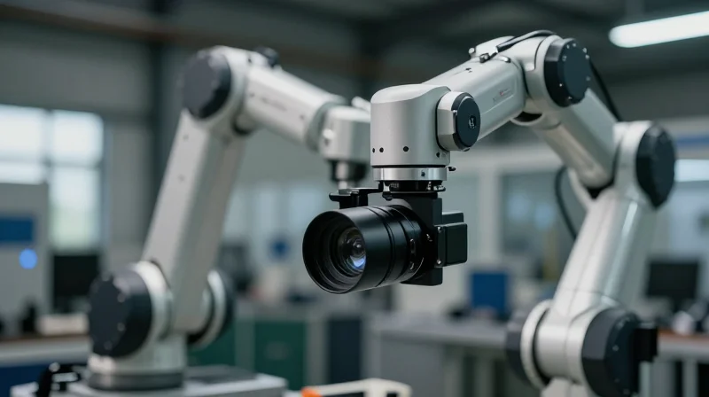
Historically, machine vision systems relied on bulky, standardized housings designed primarily for stability and ease of integration in static environments. However, the current industrial landscape demands unprecedented levels of mobility. As collaborative robots (cobots) and autonomous mobile robots (AMRs) become ubiquitous, the requirement for compact, lightweight, and vibration-resistant camera modules has accelerated. This transition is not merely cosmetic; it is a fundamental shift in how vision hardware interfaces with mechanical constraints.
Design Constraints and Form Factor Drivers
- Collaborative Robotics
Smaller form factors allow cameras to be mounted directly on end-effectors without compromising the payload capacity or movement range of the robotic arm. - Space-Constrained Integration
Modern smart factories feature dense automation clusters where traditional large-format cameras simply cannot fit into the physical envelope of the machinery. - Reduced Thermal Mass
Compact designs help manage heat distribution in confined spaces, allowing for better thermal performance without the need for large, heavy heat sinks.
Comparing Structural Architectures
| Feature | Traditional Rigid PCBs | Rigid-Flex PCBs |
|---|---|---|
| Spatial Efficiency | Limited: Requires fixed footprints | High: Folds into tight enclosures |
| Mechanical Reliability | Good, but prone to connector failure | Superior: Fewer connectors, dynamic bending |
| Manufacturing Complexity | Low: Standard assembly processes | High: Requires specialized fabrication |
| Application Scope | Stationary inspection stations | Robotics, wearables, and AMRs |
While traditional rigid PCBs remain the standard for cost-sensitive, stationary applications, the transition toward rigid-flex architectures is becoming a strategic necessity for high-performance vision systems. By utilizing rigid-flex, manufacturers can eliminate bulky cables and connectors that often serve as points of failure in high-vibration environments, effectively packaging complex image processing circuitry into the minimal footprint required by the next generation of industrial sensors.
Deconstructing Traditional Rigid PCB Architectures
The Architectural Bottlenecks of Rigid-Only Systems
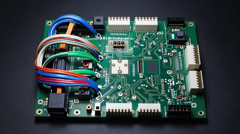
Conventional machine vision cameras typically rely on multiple rigid PCBs interconnected via header-and-socket cable assemblies or flexible flat cables (FFCs). While cost-effective for legacy designs, this modular approach introduces inherent physical constraints. As vision sensors demand higher pixel counts and faster data throughput, the overhead of managing bulky connectors and thick cabling limits the miniaturization potential of robotic vision platforms.
Limitations in Design and Integration
- Mechanical Vulnerability
Traditional connectors are prone to vibration-induced failures, contact fretting, and oxidation in industrial environments, leading to intermittent signal integrity issues. - Space and Volumetric Efficiency
The need for connector clearances and cable bend radii forces designers to increase chassis volume, conflicting with the goal of ultra-compact, high-density machine vision nodes. - Signal Integrity Challenges
High-speed data lanes—such as MIPI CSI-2 or GMSL—suffer from impedance discontinuities at each mating point, creating EMI risks that are difficult to mitigate in rigid-only stacked configurations.
Comparing Traditional Multi-Board Systems vs. Integrated Architectures
| Feature | Traditional Rigid PCBs | Integrated Rigid-Flex |
|---|---|---|
| Connection Method | Cables/Connectors | Embedded Flex Layers |
| Failure Points | High (Connector fatigue) | Low (Solid-state path) |
| Assembly Effort | Manual/Labor-intensive | Automated/High-yield |
| Size/Volume | Bulky | Minimalist |
By eliminating mechanical connectors, engineers can transition from a 'collection of boards' to a singular, cohesive circuit architecture. This shift not only reduces the Bill of Materials (BOM) complexity but also drastically improves the reliability of camera systems deployed in harsh factory automation settings, where motion and thermal cycling are persistent threats to connectivity.
Understanding Rigid-Flex Technology
The Architecture of Rigid-Flex Systems
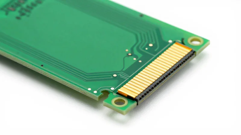
Rigid-flex technology merges the mechanical stability of rigid FR4 substrates with the versatility of flexible polyimide layers. By laminating these materials into a singular unit, designers can route signals through 3D space, eliminating the need for rigid-to-rigid connectors. This integration not only reduces the mechanical profile of the camera but also minimizes signal integrity degradation caused by parasitic resistance in traditional board-to-board interconnects.
Key Performance Indicators: Rigid vs. Rigid-Flex
| Feature | Rigid PCB Assembly | Rigid-Flex Assembly |
|---|---|---|
| Form Factor | Voluminous | Compact/Contoured |
| Connection Reliability | Low (High Connector Fatigue) | High (Continuous Copper Paths) |
| Signal Integrity | Subject to Connector Noise | Excellent (Low Impedance) |
| Weight | Significant | Ultra-lightweight |
Technical Advantages for Vision Systems
- How does rigid-flex improve vibration resistance?
By eliminating mechanical connectors, rigid-flex circuits remove common points of failure where fretting or disconnects occur in high-vibration robotic vision environments. - Can rigid-flex support high-speed data transmission?
Yes, it provides a shorter, more direct transmission path for high-speed differential pairs like MIPI CSI-2, which is essential for low-latency machine vision processing. - Does this technology reduce assembly complexity?
It significantly reduces the assembly bill of materials by removing discrete cables, connectors, and solder joints, streamlining both manufacturing and quality control processes.
Ultimately, the shift to rigid-flex is dictated by the physics of miniaturization. As machine vision sensors shrink to fit into surgical robotics or drones, the ability to fold circuitry around internal components becomes a fundamental design requirement rather than a premium feature.
Space Efficiency and 3D Packaging Advantages

The 3D Packaging Paradigm
Traditional rigid PCB architectures rely on a 2D layout philosophy, forcing designers to flatten electronics into a single plane or rely on cumbersome, high-profile vertical connectors. This approach creates significant 'dead space' within enclosures. Rigid-flex technology shifts this paradigm toward a 3D packaging strategy, where circuits can be folded, coiled, or routed around internal obstacles. By treating the PCB as a structural component that can bend, engineers can reclaim volume previously wasted on ribbon cables and bulky wire harnesses, allowing for a significantly smaller camera housing without sacrificing computational performance.
Space Optimization: Rigid vs. Rigid-Flex
| Feature | Traditional Rigid PCB | Rigid-Flex PCB |
|---|---|---|
| Form Factor | Fixed 2D Plane | Dynamic 3D Foldable |
| Interconnect Profile | Bulky Connectors/Cables | Integrated Flexible Circuits |
| Volume Utilization | Inefficient (Dead Space) | High (Contour Fitting) |
| Mechanical Reliability | Low (Connector Failure) | High (Continuous Path) |
Engineering Advantages of Folding Electronics
Beyond mere size reduction, rigid-flex integration improves the signal integrity of high-speed machine vision data. Removing mechanical connectors mitigates points of failure often caused by thermal cycling or vibration—common occurrences in factory automation. The continuous copper path reduces impedance discontinuities that occur at board-to-cable interfaces, ensuring that high-resolution frame data travels from the sensor to the processing unit with minimal interference.
Frequently Asked Questions
- How does rigid-flex technology reduce the overall footprint of a camera?
By replacing multiple discrete boards connected by bulky cables with a single monolithic rigid-flex structure, designers can fold the circuitry into the specific geometry of the device housing. - Does the folding process impact electrical performance?
When properly designed, the flexible polyimide substrate maintains consistent signal integrity and reduces the need for shielding hardware, often improving performance over long cabling runs. - Is rigid-flex more reliable in a vibrating environment?
Yes. Eliminating mechanical connectors removes the primary point of failure for vibration-induced contact intermittent issues, resulting in a more ruggedized, monolithic interconnect.
Reliability and Vibration Resistance in Industrial Environments
Eliminating Mechanical Vulnerabilities
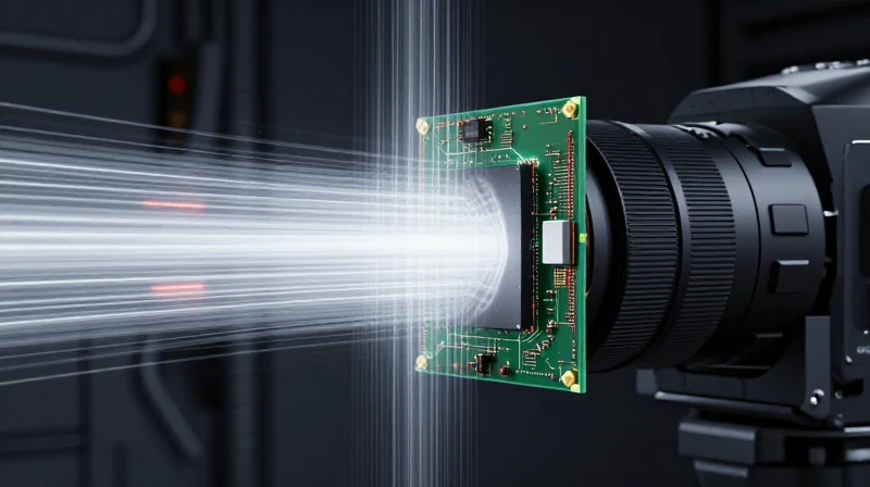
In standard machine vision systems, traditional rigid boards rely on mechanical connectors, ribbon cables, and solder joints to bridge separate modules. In high-vibration factory settings—such as robotic assembly lines or high-speed sorting machines—these physical connection points serve as the primary failure nodes. Thermal expansion cycles, constant mechanical agitation, and micro-vibrations often lead to 'fretting corrosion' or intermittent connectivity issues at these junctions. Rigid-flex technology solves this by replacing fragile connectors with a continuous, unified circuit structure that effectively removes the 'weakest link' in the interconnect chain.
Comparative Reliability Metrics
| Failure Factor | Traditional Rigid PCB | Rigid-Flex PCB |
|---|---|---|
| Mechanical Connections | Multiple connector headers | None (Monolithic construction) |
| Vibration Sensitivity | High (Cable resonance) | Low (Integrated mass) |
| Signal Integrity Loss | High via impedance mismatches | Minimal (Direct transmission) |
| Thermal Stress Impact | Solder joint cracking | Flexible interconnect tolerance |
Optimizing Signal Integrity Under Stress
Beyond mechanical durability, rigid-flex architectures provide superior signal integrity. By utilizing direct copper-to-copper traces that bridge rigid sections through flexible polyimide layers, the signal path remains consistent and shielded. Traditional cable assemblies introduce impedance discontinuities at every connector, creating potential reflections and signal noise that degrade image quality in high-resolution machine vision sensors. By creating a static, integrated path, rigid-flex PCBs maintain high-speed differential signal performance, even when subjected to the sustained harmonic vibrations typical of industrial automation.
Frequently Asked Questions
- How does rigid-flex survive constant mechanical shock?
The flexible portion of the PCB acts as a stress-relief zone, distributing mechanical loads away from critical solder joints and components, preventing the fracturing that plagues rigid cables. - Does rigid-flex improve signal latency compared to cables?
Yes, by eliminating intermediate connectors and using controlled-impedance flexible traces, signal reflections and electromagnetic interference are significantly reduced, resulting in cleaner data transmission.
Cost Considerations: Initial Investment vs. Lifetime Value
The Economics of Initial Investment
The initial cost profile of rigid-flex circuits is undeniably higher than traditional rigid boards. This price premium stems from complex manufacturing processes, including specialized lamination cycles, multi-layer registration requirements, and the use of flexible polyimide materials. Furthermore, the design and fabrication cycles for rigid-flex boards require greater engineering overhead to ensure material compatibility and proper routing through bend zones, which can inflate non-recurring engineering (NRE) costs.
Cost Impact Analysis: Rigid-Flex vs. Rigid
| Cost Factor | Traditional Rigid PCB | Rigid-Flex PCB |
|---|---|---|
| Material Cost | Low | High |
| Connector/Cable Usage | High | Minimal |
| Assembly Labor | Moderate | Low |
| Maintenance Needs | High | Low |
| Design Complexity | Low | High |
Long-Term Value and ROI
The value proposition of rigid-flex technology is found in operational savings. By integrating the interconnect system directly into the board, manufacturers eliminate the need for expensive high-density connectors, wiring harnesses, and the labor-intensive manual assembly they require. In high-precision machine vision systems, these mechanical connections are often the most common points of failure. By replacing them with a continuous circuit, companies realize significant savings through reduced downtime, fewer warranty claims, and decreased maintenance intervals.
Frequently Asked Questions
- Does the elimination of connectors justify the higher PCB cost?
Yes, for high-volume or high-reliability applications, the reduction in labor, testing, and potential connector failure typically offsets the initial investment in rigid-flex boards. - How does rigid-flex technology impact product scaling?
It simplifies the final product assembly process, allowing for faster throughput on the production line and reducing human-induced assembly errors. - Are there specific scenarios where rigid-flex is not cost-effective?
In extremely simple, low-cost consumer devices where space and vibration are not critical concerns, the cost-benefit analysis often favors traditional rigid boards.
Impact on Automated Manufacturing and Assembly

Simplifying the Automated Assembly Pipeline
In the production of high-volume machine vision cameras, assembly efficiency is often dictated by the complexity of the internal interconnects. Rigid-flex PCB architectures significantly simplify this pipeline by consolidating multiple rigid boards and cabling into a single, unified circuit structure. This reduction in disparate parts not only minimizes the number of pick-and-place operations required but also eliminates the risk of human error associated with manual cable routing and connector mating.
| Assembly Metric | Traditional Rigid PCB | Rigid-Flex PCB |
|---|---|---|
| Connector count | High (Multi-board links) | Minimal (Direct integration) |
| Assembly time | Long (Manual wiring steps) | Short (Automated pick-and-place) |
| Failure points | High (Solder joint fatigue) | Low (Integrated flexible traces) |
| Volume footprint | Bulkier, fixed form factor | Optimized, foldable topology |
Optimizing Supply Chain and Yield
By shifting toward a singular rigid-flex substrate, manufacturers effectively reduce the bill of materials (BOM), leading to a more resilient supply chain. Fewer parts translate to lower inventory management overhead and reduced lead times for procurement. Furthermore, the inherent integration of signal paths into the flexible layers ensures superior repeatability—a critical metric for vision systems where signal consistency determines the precision of image processing algorithms.
Frequently Asked Questions Regarding Assembly
- How does rigid-flex impact SMT throughput?
Rigid-flex boards are designed to fit standard surface mount technology (SMT) assembly equipment, often allowing panels to be processed as a single unit rather than individual board-to-cable assemblies, which significantly boosts throughput. - Does rigid-flex require specialized handling?
While standard SMT lines can process these boards, they often require custom support fixtures or carrier plates to ensure the flexible segments remain stable during the solder paste and reflow process. - Can rigid-flex reduce final testing complexity?
Yes, by eliminating connector variability and physical cabling, the electrical path becomes more predictable, which reduces noise interference during diagnostic testing and final calibration of optical sensors.
Future Outlook: The Role of Flexible Electronics in Smart Factories
Redefining Spatial Efficiency in Automated Inspection
As smart factories transition toward more complex, multi-modal sensing environments, the role of rigid-flex PCBs becomes critical. Unlike traditional rigid boards that dictate a specific, often bulky, industrial design, rigid-flex circuits allow machine vision modules to conform to the tight geometries of robotic end-effectors and compact sensor housings. This spatial freedom supports the integration of high-speed processing and optical sensors in locations previously inaccessible to rigid hardware.
Evolution of Materials and Machine Vision Integration
| Feature | Traditional Rigid PCB | Rigid-Flex PCB |
|---|---|---|
| Form Factor | Fixed and Bulky | Conformal and Adaptive |
| System Dynamics | Susceptible to Connector Failure | Monolithic, High-Vibration Resilience |
| Integration | Requires External Cabling | Integrated Interconnects |
Strategic Advantages in Smart Environments
- How does rigid-flex tech enhance real-time vision?
By removing mechanical connectors and bulky cabling, signal path latency is reduced, and signal integrity is maintained even in high-speed, dynamic robotic movements. - Will rigid-flex architectures reduce factory downtime?
Yes, by eliminating potential points of failure such as loose cables and connector pins, these circuits offer superior reliability in harsh industrial environments. - Is the transition to flexible electronics cost-effective?
While prototyping costs are higher, the reduction in assembly complexity and long-term maintenance costs provides a superior return on investment for large-scale smart factory deployments.
The future of machine vision hinges on the ability to embed intelligence closer to the source of data. Rigid-flex technology acts as the enabling backbone for the next generation of 'aware' robots, allowing for thinner, lighter, and more durable camera systems that push the boundaries of industrial automation efficiency.
The transition to rigid-flex PCB technology is no longer just an optional upgrade; it is a fundamental shift toward more reliable, compact, and efficient machine vision systems. By streamlining your hardware architecture today, you prepare your infrastructure for the complex demands of tomorrow’s smart factory. Contact our engineering team today to learn how our advanced circuit solutions can optimize your next-generation machine vision camera design.
