
The medical imaging landscape is undergoing a radical transformation as ultrasound technology moves from cart-based systems to handheld, pocket-sized devices. For design engineers, this shift necessitates a fundamental rethink of interconnect technology. While rigid-flex boards have long been the standard for complex geometry, the surge in demand for high-fidelity, high-density performance is pushing HDI (High-Density Interconnect) architectures to the forefront. We analyze the technical trade-offs defining the future of point-of-care diagnostics.
The Evolution of Ultrasound: Shrinking Form Factors, Growing Demands
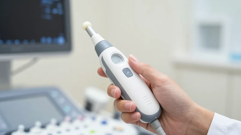
Ultrasound technology has undergone a seismic shift over the last decade, transitioning from room-sized, cart-based consoles to sophisticated handheld transducers. This evolution has redefined clinical accessibility, allowing for rapid diagnostics at the point of care. However, this portability imposes extreme physical constraints on the internal electronics, requiring a radical departure from legacy PCB design methodologies.
The Engineering Challenge of Miniaturization
As imaging form factors shrink, the surface area available for signal processing, thermal management, and power distribution decreases exponentially. Designers must now pack high-speed imaging circuitry into a fraction of the space previously afforded by traditional racks. This environment demands a move beyond standard rigid boards or bulky rigid-flex combinations toward advanced HDI PCBs, which leverage micro-vias and high-layer counts to maintain signal integrity in constrained volumes.
| Feature | Traditional Rigid-Flex | HDI PCB Technology |
|---|---|---|
| Component Density | Low to Moderate | Ultra-High |
| Via Structure | Standard Through-Hole | Laser-Drilled Micro-vias |
| Space Utilization | Bulky/Flexible interconnects | Integrated Layer Stacking |
| Thermal Dissipation | Moderate | Excellent (via thermal vias) |
Frequently Asked Questions
- Why is HDI preferred for handheld ultrasound?
HDI technology allows for tighter component placement and complex routing through micro-vias, essential for fitting high-speed signal processing chips into handheld enclosures. - What are the limitations of traditional rigid-flex in this context?
Rigid-flex often requires more volumetric space for bends and mechanical reinforcement, which creates unnecessary bulk that limits the ergonomics of modern portable probes. - Does HDI impact signal integrity?
While HDI design is more complex, it actually improves signal integrity by reducing trace lengths and minimizing parasitic capacitance, which is vital for high-frequency ultrasound imaging.
Anatomy of Modern HDI PCB Architectures

Core Pillars of HDI Architectures
The transition from traditional rigid-flex to HDI architectures is defined by the move toward sequential build-up (SBU) processes. By utilizing laser-drilled micro-vias rather than mechanical through-holes, HDI designs reclaim significant surface area on both inner and outer layers, allowing for denser routing patterns and smaller footprints. This structural shift is essential for integrating high-speed imaging processors and ultra-low-power sensing components into compact medical enclosures.
Key Design Elements in HDI Medical PCBs
- Micro-vias (Laser-drilled)
Small diameter vias typically drilled by lasers that connect surface layers to adjacent internal layers without penetrating the entire board thickness, drastically saving space. - Blind and Buried Vias
Blind vias connect an outer layer to an inner layer, while buried vias exist entirely between internal layers, allowing for complex signal routing in restricted Z-axis dimensions. - Staggered and Stacked Via Structures
Advanced stacking methods allow vias to be placed directly on top of each other, creating vertical signal channels that drastically reduce routing congestion.
HDI vs. Traditional Rigid-Flex: Comparative Analysis
| Feature | Traditional Rigid-Flex | HDI Technology |
|---|---|---|
| Via Type | Mechanical Through-hole | Laser-drilled Micro-via |
| Component Density | Moderate | Ultra-High |
| Design Complexity | Low to Medium | High |
| Z-axis Efficiency | Limited by hole size | Maximized via stacking |
Engineering Considerations for Medical Imaging
When deploying HDI in medical diagnostic tools, signal integrity becomes the primary bottleneck. As component density increases, electromagnetic interference (EMI) and crosstalk risks rise proportionally. Effective HDI implementation requires sophisticated stack-up planning to isolate sensitive analog frontend signals from high-speed digital processing data, ensuring that the miniaturization does not compromise diagnostic precision.
Traditional Rigid-Flex: Strengths and Limitations in Medical Hardware
The Traditional Rigid-Flex Paradigm
For decades, rigid-flex PCBs have been the gold standard for medical devices that require high-density interconnects in tight, non-planar environments. By integrating rigid FR4 sections for high-component-density areas with flexible polyimide layers to bridge gaps, designers have effectively replaced bulky wiring harnesses and connectors. This structural efficiency is critical in devices like portable ultrasound probes and endoscopic cameras, where physical space is at a premium and device movement is inherent.
Strengths and Technical Hurdles
| Attribute | Rigid-Flex Advantage | Inherent Limitation |
|---|---|---|
| Mechanical | Superior structural flexibility and durability. | Complex mechanical fatigue management. |
| Assembly | Elimination of interconnects and cabling. | High manufacturing complexity/cost. |
| Signal Integrity | Provides reliable high-speed paths. | Impedance discontinuities in transition areas. |
Key Considerations for Medical Hardware Design
- Why does signal integrity suffer in traditional rigid-flex?
The transition zones between rigid and flexible materials often cause impedance mismatches. At the high frequencies required for modern ultrasound imaging, these discontinuities can lead to signal reflections and attenuation. - How does manufacturing complexity impact medical timelines?
Rigid-flex requires specialized multi-stage bonding processes. Any design iteration often involves lengthy re-tooling phases, creating a bottleneck compared to standardized HDI processes. - Are there limits to component density?
While rigid-flex allows for compact form factors, it often relies on traditional via technology. This limits the total trace routing density when compared to modern HDI micro-via architectures.
While rigid-flex remains a viable solution for many electromechanical medical systems, the rapid push toward miniaturization and higher data throughput in imaging hardware is beginning to outpace the electrical design limits of traditional rigid-flex. As the industry migrates toward higher performance, the need for the superior interconnect density offered by HDI technologies becomes increasingly unavoidable.
Comparative Performance: HDI vs. Rigid-Flex in High-Frequency Signal Paths
Impedance Control and Signal Integrity
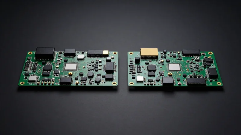
In high-frequency medical imaging, such as portable ultrasound or high-resolution endoscopy, the reliability of signal paths is paramount. Traditional rigid-flex designs often struggle with impedance discontinuities at the interface where rigid boards meet flexible circuits, primarily due to the disparate dielectric constants of polyimide versus rigid substrates. HDI (High-Density Interconnect) PCBs offer a monolithic dielectric structure, enabling tighter control over trace geometry and consistent impedance profiles across the entire high-frequency transmission line.
| Feature | HDI PCB Performance | Rigid-Flex Performance |
|---|---|---|
| Impedance Stability | High (Uniform Dielectric) | Moderate (Transition Mismatches) |
| Signal Path Length | Ultra-Short (Via-in-Pad) | Extended (Connector Routing) |
| Electromagnetic Interference | Low (Integrated Shielding) | High (Susceptible at Joints) |
| Frequency Bandwidth | Broadband Support | Limited by Interface Reflection |
Key Advantages of HDI over Rigid-Flex
- Why does HDI offer better signal clarity?
HDI utilizes laser-drilled micro-vias that dramatically reduce stub lengths and parasitic capacitance, allowing for cleaner high-frequency signal propagation compared to traditional through-hole vias found in rigid-flex. - How does integration impact reliability?
By eliminating mechanical connectors between rigid and flex sections, HDI designs reduce points of failure and thermal expansion mismatches, both of which are critical for medical imaging sensors subjected to frequent handling. - Can HDI replace flex in all medical applications?
While HDI excels in high-speed data throughput and miniaturization, rigid-flex remains the standard for applications requiring repetitive dynamic bending; however, for static high-speed imaging sensors, HDI is becoming the preferred solution for superior signal integrity.
Thermal Management Challenges in Miniaturized Imaging Systems

Thermal Management Challenges in Miniaturized Imaging Systems
As medical imaging devices transition toward portable, handheld form factors, the thermal density within the PCB architecture increases exponentially. HDI (High-Density Interconnect) technology exacerbates these challenges because the reduction in physical real estate prevents the use of traditional convective cooling methods. When high-layer counts are compressed into smaller volumes, heat flux can lead to signal attenuation, premature component degradation, and potential patient safety risks if the device surface temperature exceeds regulatory thresholds.
Thermal Dissipation Strategies: HDI vs. Rigid-Flex
| Feature | HDI PCB Thermal Performance | Rigid-Flex Thermal Performance |
|---|---|---|
| Heat Spreading | Superior due to micro-via arrays acting as thermal pipes | Limited by polyimide substrate low thermal conductivity |
| Component Density | Very high; requires active thermal management | Moderate; relies on dispersed placement |
| Vias | Copper-filled micro-vias for vertical heat transfer | Limited by flexible layer fatigue constraints |
Frequently Asked Questions Regarding Thermal Design
- Why do micro-vias improve thermal performance in HDI?
Micro-vias, especially when copper-filled, provide a continuous metallic path from the heat-generating component to internal ground planes, effectively moving heat away from the silicon surface. - What is the primary thermal limitation of traditional rigid-flex?
Traditional flexible materials like polyimide have significantly lower thermal conductivity compared to standard FR-4 or high-Tg materials, creating thermal bottlenecks in high-power imaging circuits. - How can designers mitigate hotspots in compact imaging arrays?
Engineers should utilize thermally conductive prepregs, integrated heat sinks embedded directly into the PCB stackup, and strategic placement of power-hungry components to maximize surface area for dissipation.
Cost-Efficiency and Manufacturability at Scale
Optimizing Lifecycle Costs through HDI Integration
While rigid-flex circuits have long been the standard for complex, space-constrained medical imaging equipment, they often introduce hidden costs through lower manufacturing yields and labor-intensive assembly processes. HDI technology shifts the economic burden toward initial design and fabrication precision, ultimately achieving lower long-term costs through higher-throughput automated surface mount technology (SMT) and simplified mechanical integration.
Comparative Efficiency Metrics
| Metric | HDI Technology | Traditional Rigid-Flex |
|---|---|---|
| Unit Assembly Time | Fast (Standard SMT) | Slow (Manual Handling Required) |
| First-Pass Yield | High (Consistent Process) | Moderate (Material Fragility) |
| Supply Chain Lead Time | Medium (Standardized Fab) | High (Specialized Material Needs) |
| Design Complexity Costs | Low to Moderate | High (Custom Flex Bonding) |
Scalability and Manufacturing Yield
In mass-market medical imaging, such as portable diagnostic ultrasound or point-of-care imaging devices, repeatability is paramount. Rigid-flex assemblies are inherently susceptible to micro-fractures in the transition zone between rigid and flexible layers during high-volume assembly. HDI boards, characterized by micro-vias and dense interconnects, utilize standard rigid substrates that eliminate these failure points, resulting in significantly higher manufacturing yields and reduced waste.
Key Considerations for Engineering Teams
- Does HDI eliminate the need for flex circuitry entirely?
Not necessarily; HDI addresses board-level density, but if the medical device requires mechanical articulation or hinges, some degree of flex or cable remains necessary. However, HDI allows for more localized rigid sections, reducing the total footprint of expensive flexible materials. - How does HDI influence total cost of ownership?
While fabrication of an HDI board per square inch can be higher, the reduction in assembly errors, faster test cycles, and superior thermal reliability leads to lower field failure rates, significantly impacting the device's lifecycle financial performance. - Is HDI easier to scale for mass production?
Yes. HDI manufacturing processes are fully automated and highly standardized across global PCB houses, unlike complex rigid-flex builds which often require specialized manual assembly and boutique manufacturing workflows.
Reliability Standards and Compliance in Patient-Facing Tech
Regulatory Standards and Certification
The transition to High-Density Interconnect (HDI) technology in medical devices is governed by rigorous quality management systems, primarily ISO 13485. Because HDI architectures allow for extreme miniaturization and complex signal routing, they introduce new failure modes that traditional rigid-flex designs might avoid. Manufacturers must demonstrate that the increased layer density does not compromise dielectric integrity or thermal stability under prolonged clinical operation.
Impact of PCB Construction on Compliance
| Feature | Rigid-Flex Compliance | HDI PCB Compliance |
|---|---|---|
| Failure Risk | Flex joint fatigue | Via-in-pad delamination |
| Trace Density | Moderate | Very High |
| Inspection | Standard AOI | Advanced X-ray/CT |
| Regulator Focus | Mechanical stress | Thermal/Dielectric stability |
Frequently Asked Questions on Medical PCB Compliance
- Does HDI PCB usage complicate FDA or CE submissions?
Yes, it necessitates more rigorous validation of micro-via reliability and thermal cycle testing compared to traditional board configurations. - How does PCB selection affect long-term patient safety?
Proper material selection and stack-up design prevent signal degradation and overheating, ensuring that diagnostic imaging remains precise throughout the device's lifecycle. - What is the primary documentation required for HDI designs?
Designers must provide extensive Test Validation Reports, including cross-sectional analysis of micro-vias and IPC-6012 Class 3 compliance documentation.
Future-Proofing Designs for Next-Gen Diagnostic Tools

The Convergence of AI and HDI Architecture
The next generation of diagnostic imaging is moving away from purely passive data acquisition toward edge-AI hardware capable of real-time inferencing. High-Density Interconnect (HDI) technology serves as the backbone for this shift, enabling the integration of high-bandwidth processing units directly adjacent to sensitive analog front-ends. By leveraging micro-via structures and finer trace routing, engineers can minimize electromagnetic interference (EMI) while simultaneously reducing signal latency—critical factors when utilizing neural networks to reconstruct imaging data in situ.
Scaling Through High-Layer HDI vs. Traditional Rigid-Flex
| Feature | Rigid-Flex | Next-Gen HDI |
|---|---|---|
| Signal Integrity | Variable/Flex-Induced | High/Consistent |
| Component Density | Moderate | Extreme |
| AI Processor Support | Limited | Native Optimization |
| Thermal Management | Challenging | Optimized Copper Pour |
Strategic Considerations for Design Longevity
- How does HDI improve AI processing?
HDI allows for shorter trace lengths and optimized impedance matching, which reduces data bottlenecks between the sensor array and the dedicated AI inference engine. - Will rigid-flex become obsolete?
Rigid-flex will remain essential for specific wearable applications requiring mechanical movement, but high-performance stationary imaging systems are rapidly standardizing on high-layer count HDI to maximize processing power. - What is the biggest risk in current designs?
The failure to account for signal thermal degradation when scaling processing power is the primary risk; future designs must prioritize advanced thermal vias and materials with higher glass transition temperatures.
Designing for the next decade necessitates a modular approach where hardware can accommodate periodic software-defined updates. By adopting HDI-centric designs, medical manufacturers create a more stable, scalable environment that avoids the mechanical fatigue points inherent in complex rigid-flex assemblies while supporting the compute-intensive future of diagnostic AI.
As portable ultrasound technology continues to bridge the gap between high-fidelity imaging and point-of-care accessibility, the choice between HDI and rigid-flex designs remains a critical engineering milestone. While rigid-flex still holds its place for specialized mechanical applications, HDI is rapidly becoming the gold standard for dense, high-performance electronics. Ensure your next medical device design is future-ready—contact our engineering team today to optimize your PCB strategy for the next generation of portable diagnostics.
