
The modern data center is at a breaking point. With rack densities exceeding 50kW, traditional infrastructure is struggling to keep pace. As engineers look for ways to optimize current flow, reduce footprint, and improve reliability, the industry is pivoting toward modular PCB-based power distribution. In this deep dive, we compare the legacy of copper busbars with the precision of rigid-flex PCB architectures to determine the future standard for server power.
The Evolution of Power Density in Hyperscale Data Centers

The Scaling Crisis in Hyperscale Power
As hyperscale facilities transition from standard cloud compute to intensive AI training and inference workloads, the demand for rack-level power density has surged. Historically, data centers operated with a power profile of 10-15 kW per rack, but current GPU-accelerated clusters are pushing past 50-100 kW per rack. This density spike creates a thermal and spatial bottleneck within the Power Distribution Unit (PDU), rendering traditional rigid busbar architectures increasingly restrictive.
The Limitations of Legacy Busbars
Traditional copper busbars served the industry well during the era of standardized, lower-power deployments. However, they rely on rigid geometries that occupy significant vertical space and require manual cabling for complex power branching. In modern PDUs, these rigid structures lack the flexibility to accommodate dense component placement, leading to airflow obstructions and complex mechanical integration challenges that hinder the rapid scaling required by modern high-performance computing (HPC) environments.
Comparative Metrics: Busbars vs. Rigid-Flex
| Feature | Traditional Busbars | Rigid-Flex PCB |
|---|---|---|
| Space Efficiency | Low (Bulky) | High (Compact) |
| Design Geometry | Fixed/Rigid | 3D Customizable |
| Installation Time | High (Manual) | Low (Modular/Plug) |
| Thermal Flow | Restricted | Optimized |
Frequently Asked Questions
- Why is power density the primary constraint for AI clusters?
AI clusters use highly concentrated GPUs that draw massive constant current, which creates localized heat zones and requires lower-impedance paths to prevent significant voltage drop. - How do rigid-flex PCBs improve power distribution?
Rigid-flex PCBs allow for high-density conductor routing in 3D spaces, enabling power distribution to reach high-wattage components directly without the need for cumbersome cabling or bulky busbar assemblies. - Are rigid-flex solutions cost-effective for hyperscalers?
While initial fabrication is more complex, the long-term TCO is reduced through improved power efficiency, reduced installation time, and the ability to pack more compute power into the same floor footprint.
Anatomy of the Legacy Busbar: Reliability vs. Design Constraints
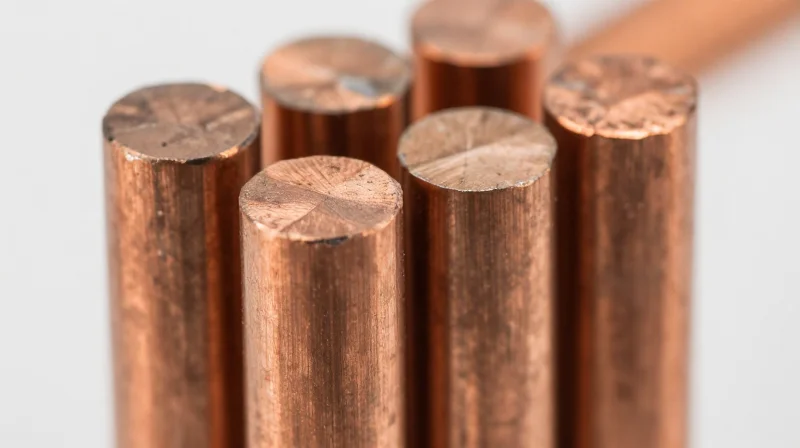
For decades, the copper busbar has served as the backbone of electrical distribution in data centers, prized for its raw conductivity, low resistance, and structural simplicity. By utilizing solid copper bars, engineers have effectively managed the distribution of high currents with minimal thermal loss. However, as power requirements shift toward 1U and 2U modular architectures, the rigidity and bulk of traditional busbars have transitioned from a design asset into a critical engineering liability.
The Conflict Between Rigidity and Compact Design
The primary drawback of legacy busbar systems lies in their spatial inflexibility. Because they are rigid, heavy components, they require substantial physical clearance and complex fastening hardware to prevent vibration-induced fatigue and short-circuit risks in dense racks. As hyperscale hardware designers push for increased vertical density, the 'keep-out' zones required to accommodate traditional busbar insulation and mechanical mounting points consume valuable board space, effectively capping the total power-per-rack capacity.
| Feature | Traditional Busbar | Legacy Constraint |
|---|---|---|
| Form Factor | Rigid, bulky | Large spatial footprint |
| Installation | Mechanical bolting | Complex labor requirements |
| Scalability | Fixed dimensions | Limited to straight-line runs |
| Weight | High mass | Increases rack structural load |
Common Challenges in Legacy Power Infrastructure
- Why is thermal management difficult with busbars?
Busbars act as large heat sinks, but their rigid nature limits the ability to integrate sophisticated airflow paths or local sensor arrays directly into the distribution path. - How does vibration affect reliability?
In high-density environments with cooling fans and dynamic loads, mechanical connections (bolted joints) on busbars are prone to loosening over time, increasing contact resistance and the risk of localized hotspots. - What is the primary constraint for modularity?
Traditional busbars require custom fabrication for each design iteration, preventing the 'plug-and-play' modularity required by modern, rapid-deployment server architectures.
Ultimately, the reliance on rigid copper represents a trade-off between absolute conductivity and design agility. While current-carrying capacity remains excellent, the inability of these components to adapt to the three-dimensional routing needs of next-generation PDUs necessitates a paradigm shift toward more flexible, high-density interconnection technologies.
Emerging PCB-Based PDU Technologies: Precision and Compactness
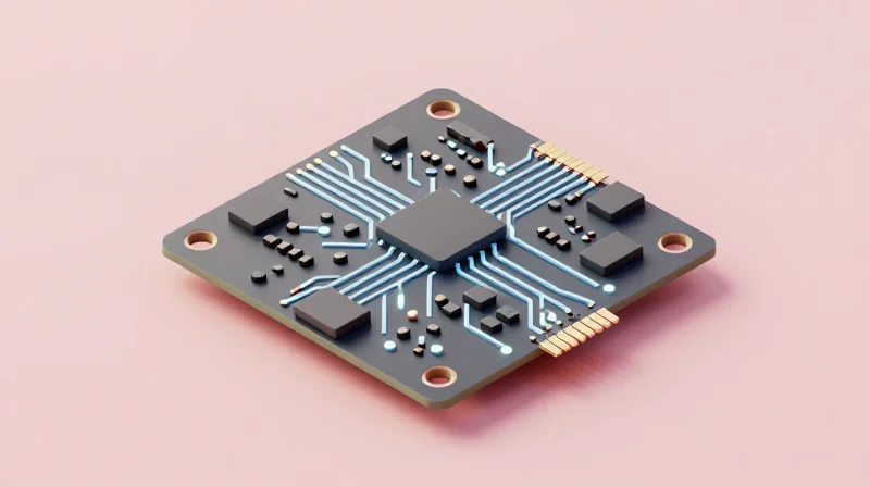
Precision Engineering Through Rigid-Flex Architecture
The shift toward PCB-based power distribution units (PDUs) is fundamentally an exercise in geometric optimization. Unlike traditional metal busbars—which rely on manual bending, punching, and rigid mechanical fastening—rigid-flex PCBs allow power paths to be routed in complex, multi-dimensional planes. By embedding high-current copper layers within a multi-layer flexible substrate, engineers can integrate logic, sensing, and power delivery into a single cohesive assembly, effectively eliminating the bulky cabling and connectors that typically plague power delivery networks.
Performance Comparison: Rigid-Flex PCBs vs. Busbars
| Feature | Traditional Busbar | Rigid-Flex PCB PDU |
|---|---|---|
| Routing Complexity | Linear/Fixed | Multi-dimensional/Dynamic |
| Component Density | Low | Very High |
| Integration | Discrete connections | System-level integration |
| Thermal Profile | Passive/Conduction | Active/Managed via layout |
Architectural Benefits of PCB-Based Power
The primary advantage of transitioning to PCB-based power is the ability to maintain uniform current density even in tight, irregular spaces. Traditional copper busbars create localized hot spots at mechanical joints and interfaces. In contrast, rigid-flex PCBs provide a continuous, low-impedance path that minimizes parasitic inductance—a critical requirement for modern high-frequency AI compute modules that demand rapid, transient power delivery.
- How does PCB thickness impact current carrying capacity?
Modern PDU design utilizes heavy-copper PCB fabrication processes, often exceeding 6oz or 10oz copper weights, to match or exceed the current capacity of thin busbars while maintaining a compact footprint. - Why is impedance matching critical in modern PDU design?
Lowering parasitic impedance is essential to preventing voltage droop during rapid state-change events in high-performance processors, a feat made easier through the controlled dielectric spacing found in PCB manufacturing. - Can rigid-flex PCBs be serviced in the field?
While traditional busbars are often modular in a brute-force sense, PCB-based PDUs are designed for 'hot-swappable' integration where the entire module acts as the interconnect, significantly reducing Mean Time To Repair (MTTR).
Comparative Analysis: Thermal Performance and Conductivity
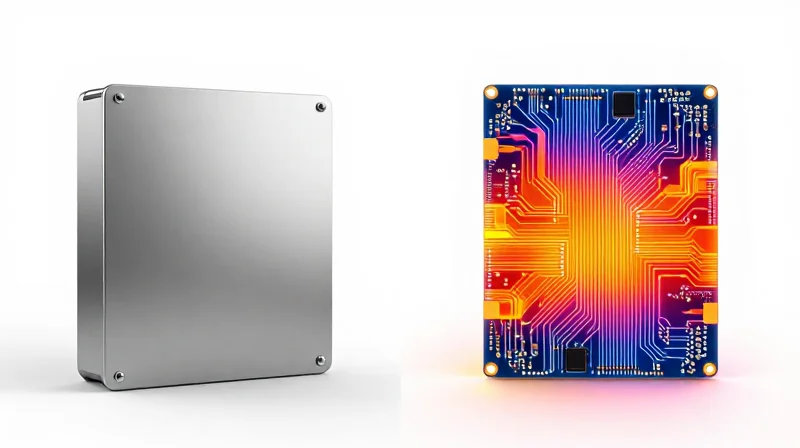
The fundamental difference in thermal performance between rigid-flex PCBs and traditional copper busbars lies in the management of heat density. While busbars rely on large metallic cross-sections and natural convection to manage temperature rise, rigid-flex PCBs utilize localized copper planes and engineered heat-spreading vias, allowing for more precise thermal profiles in space-constrained environments.
Comparative Thermal Characteristics
| Feature | Rigid-Flex PCB | Traditional Busbar |
|---|---|---|
| Heat Dissipation | Localized via thermal vias | Passive bulk dissipation |
| Thermal Mass | Low; requires heat spreading | High; acts as heat sink |
| Surface Area | Optimized via traces/planes | Direct exposure to airflow |
| Hotspot Control | High (Precision routing) | Low (Uniform heating) |
Conductivity and Thermal Stability
Conductivity in PCB-based PDU architectures is a product of trace geometry and layer stacking. Unlike the monolithic nature of a busbar, which exhibits consistent conductivity across its entire length, rigid-flex PCBs allow for varying copper thicknesses to match current-carrying requirements exactly. This granularity prevents excessive heat generation in low-current zones and enables active thermal monitoring via embedded sensors.
Frequently Asked Questions on Thermal Design
- How does high current affect PCB substrate integrity?
Modern high-Tg (glass transition temperature) FR-4 or polyimide materials ensure that substrates maintain structural stability even as copper traces approach higher operating temperatures. - Can rigid-flex PCBs replace heavy-duty busbars in high-amperage systems?
While PCBs offer superior design flexibility, extreme amperage applications often still benefit from the raw mass of busbars, leading to hybrid systems that combine both technologies. - Why are thermal vias essential in PCB-based PDUs?
Thermal vias act as heat conduits that pull energy away from high-density trace layers, effectively transferring heat to secondary cooling surfaces or the chassis.
Scalability and Modular Integration
Optimizing Modular Assembly Through PCB Integration
The shift toward software-defined data centers necessitates power delivery architectures that can scale rapidly without manual re-cabling. Unlike rigid metal busbars, which require bespoke mechanical mounting and significant volumetric space, rigid-flex PCBs provide a three-dimensional interconnect solution. By integrating power distribution directly into the chassis structural components, engineers can utilize plug-and-play modules that reduce mechanical assembly time by up to 40%.
Comparison of Scalability Features
| Feature | Traditional Busbars | Rigid-Flex PCB PDU |
|---|---|---|
| Modular Hot-Swapping | High physical resistance; requires manual fastening | Integrated blind-mate connectors; seamless |
| Density Scalability | Low; constrained by rigid geometry | High; multilayer stacking allows compact routing |
| Installation Labor | Manual, high torque requirements | Automated assembly, snap-fit compatible |
Frequently Asked Questions on Modular Power
- How do rigid-flex PCBs improve rack-level scalability?
They allow power pathways to be routed through tight, non-linear geometries that busbars cannot navigate, enabling more dense components per rack unit. - Can PCB-based PDUs handle high-current loads equivalent to busbars?
Yes, through advanced multi-layer copper weight optimization and internal trace paralleling, PCBs effectively replace traditional copper bars while offering superior signal integration. - Does the modular nature of PCB PDUs increase field maintenance complexity?
Actually, it decreases complexity; by utilizing standardized connector interfaces, field technicians can perform hot-swaps without specialized tools or risk of electrical shorting.
Cost-to-Performance Ratio: Beyond the Initial Build
Total Cost of Ownership: A Financial Breakdown
When comparing rigid-flex PCBs to traditional busbar systems, the total cost of ownership (TCO) is defined by the trade-off between higher component precision and reduced secondary labor. While rigid-flex PCBs typically carry a higher initial material cost due to complex multi-layer manufacturing processes, they offer significant savings through the elimination of manual wiring, reduced connector counts, and automated assembly workflows. Conversely, busbars leverage inexpensive raw copper stock but often incur higher costs in the assembly phase due to the necessity of manual mounting, specialized fastening hardware, and increased error rates associated with manual installation.
| Cost Factor | Rigid-Flex PCB | Traditional Busbars |
|---|---|---|
| Material Cost | High | Low |
| Assembly Speed | Fast (Automated) | Slow (Manual) |
| Maintenance Requirement | Low (Integrated) | Medium (Vibration prone) |
| Failure Rates | Low (Low interconnect) | Variable (Connection points) |
Hidden Operational Efficiencies
The long-term performance benefits of rigid-flex circuits often offset the higher entry price through reduced field failure rates. Because rigid-flex designs consolidate multiple components into a single, cohesive unit, the number of potential points of failure is drastically reduced compared to busbar assemblies that rely on bolts, crimps, and secondary cabling. For data centers and high-density computing environments, the reduction in maintenance labor and unplanned downtime contributes to a significantly lower TCO over the typical five-to-ten-year lifecycle of the PDU.
Frequently Asked Questions on Economic Impact
- Does the complexity of rigid-flex design increase replacement costs?
While a single replacement PCB is more expensive than a raw copper bar, the failure rates are statistically lower. The reduced necessity for human intervention during assembly minimizes the risk of human-error-induced failures. - At what scale do rigid-flex PCBs become more cost-effective?
Rigid-flex solutions reach peak cost-efficiency in high-density, modular PDU applications where the savings in assembly labor and reduction of manual cabling footprints outweigh the premium cost of the advanced substrates. - Do busbars offer better value in any scenarios?
Yes, for high-amperage, simple distribution paths where space is not constrained and high thermal mass is required to manage heavy, continuous electrical loads, traditional busbars remain the most cost-effective option.
Navigating the Transition: Challenges in Implementing PCB PDUs
Engineering Hurdles in PCB Power Integration
Moving from mechanical busbars to rigid-flex PCB architectures necessitates a fundamental shift in how engineers manage high current density. While busbars offer massive cross-sectional area for current flow, PCB traces are limited by copper weight, layer count, and substrate thermal conductivity. Achieving equivalent current-carrying capacity requires innovative layout strategies, such as heavy copper plating and optimized thermal relief paths, to prevent localized hotspots that could compromise board integrity over time.
Technical Barriers to Adoption
| Challenge | Impact | Mitigation Strategy |
|---|---|---|
| Current Density | Trace overheating/delamination | High-weight copper and multi-layer parallel planes |
| Signal Integrity | EMI/RFI in power rails | Advanced shielding and differential pair routing |
| Manufacturing | Yield sensitivity on large boards | Panelization and rigid-flex hybrid design |
Frequently Asked Questions
- Can standard PCB manufacturing handle PDU-level current?
Standard fabrication processes are insufficient for high-power distribution. Engineers must specify heavy copper (3oz to 6oz+), integrated busbars, or conductive paste technologies to achieve the required conductivity. - How does rigid-flex complexity affect long-term reliability?
The transition points between rigid and flex regions are failure-prone under high thermal cycling. Utilizing specialized polyimide materials and stress-relief patterns during layout is essential to prevent micro-cracks. - Is signal noise a factor in PCB PDUs?
Yes. High-frequency switching transients in modern racks can cause EMI. PCB designs must incorporate robust ground planes and decoupling strategies that traditional busbar systems lack.
The Strategic Verdict: Selecting Your Power Path

The Strategic Verdict: Selecting Your Power Path
The choice between rigid-flex PCBs and traditional busbars is no longer a binary decision between legacy and innovation, but a strategic alignment of hardware architecture with specific application performance requirements. While busbars remain the undisputed standard for high-amperage, high-reliability power paths in data centers, rigid-flex PCBs are rapidly capturing the market for space-constrained, high-density, and highly complex modular systems where signal intelligence must coexist with power delivery.
| Feature | Busbar Architecture | Rigid-Flex PCB |
|---|---|---|
| Current Density | High (Excellent for high power) | Moderate (Requires multi-layer/thick copper) |
| Modularity | Mechanical/Manual | Integrated/Automatic |
| Signal Integration | Difficult (Requires separate looms) | Native (Power & Data on same plane) |
| Manufacturing | Well-understood/Robust | Complex/Specialized |
Decision Framework
Engineering teams should employ a tiered decision matrix to determine the viability of their power architecture. If your design prioritizes bulk power distribution, thermal mass, and low-cost manufacturing at scale, traditional busbars remain the most efficient path. Conversely, if your PDU requires intelligent feedback loops, complex geometric routing, and ultra-compact footprints, the transition to rigid-flex PCB architectures offers a significant competitive advantage in volume reduction and assembly speed.
- When should I prioritize busbars?
Prioritize busbars when your system requires high-current tolerance (>100A per phase), minimal voltage drop, and operating environments with high vibration or thermal cycling where robust, rigid connections are paramount. - When is the rigid-flex PCB transition justified?
The transition is justified when the PDU design integrates complex monitoring components, requires tight spatial routing that prohibits standard busbar geometry, or when the assembly labor for complex cable harnesses exceeds the ROI of custom PCB fabrication. - Are there hybrid approaches available?
Yes, many modern PDUs utilize a hybrid strategy, leveraging heavy-duty busbar rails for primary high-current distribution while employing flexible circuits for local sensor distribution, board-to-board communication, and low-current control signals.
As the demand for hyper-efficient data centers grows, the transition from rigid busbars to advanced PCB-based power distribution represents a major technological leap. While busbars remain reliable for lower-density applications, the modularity and intelligence offered by PCB technology are undeniable assets for future-proofing your infrastructure. Contact our engineering team today to audit your current power distribution strategy and explore a transition to the next generation of rack-scale power.
