
As satellite constellations expand into higher frequency bands, the demand for superior signal integrity has never been higher. Engineers are now at a crossroads: stick with the proven, yet limiting, nature of traditional PTFE or embrace the next generation of ceramic-filled materials. This article breaks down the technical imperatives of this shift to ensure your next design mission succeeds in orbit.
The Evolution of Frequency: From Ku to V-Band
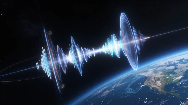
The Shift Toward Higher Frequency Bands
As global demand for data throughput reaches unprecedented levels, the satellite industry is moving away from the congested Ku and Ka bands toward the V-band (40–75 GHz). While moving to higher frequencies provides massive increases in available bandwidth, it introduces severe engineering hurdles. Higher frequency operation results in exponentially higher insertion loss and dielectric absorption, demanding materials with extremely low dissipation factors and tighter manufacturing tolerances to maintain signal integrity.
Comparing Operational Characteristics
| Feature | Ku-Band | V-Band |
|---|---|---|
| Frequency Range | 12–18 GHz | 40–75 GHz |
| Bandwidth Availability | Moderate | Very High |
| Signal Propagation | Stable/Weather Resilient | High Atmospheric Absorption |
| Material Sensitivity | Standard PTFE | Ultra-Low Loss Advanced Composites |
Material Challenges in V-Band Environments
In the V-band, the parasitic losses within traditional PTFE-based laminates become a limiting factor. The increase in frequency forces a tighter reliance on the laminate's dielectric constant (Dk) stability and surface profile. At these frequencies, the copper foil roughness significantly impacts insertion loss, leading designers to shift toward laminates with ultra-low profile copper and advanced resin systems that maintain thermal stability under high-power density conditions.
- Why is V-band adoption necessary?
Lower frequency bands like Ku and Ka are reaching spectral saturation; V-band opens the wide swaths of spectrum required for high-throughput satellite (HTS) constellations. - What is the primary drawback of moving to V-band?
The primary drawback is increased path loss due to atmospheric oxygen and water vapor absorption, coupled with higher sensitivity to dielectric material losses. - How do material requirements change at 60 GHz?
Engineers must prioritize low-loss tangents (Df), tighter dielectric constant (Dk) tolerances, and superior thermal conductivity to prevent performance degradation caused by heat buildup.
Deconstructing PTFE-Based Laminates
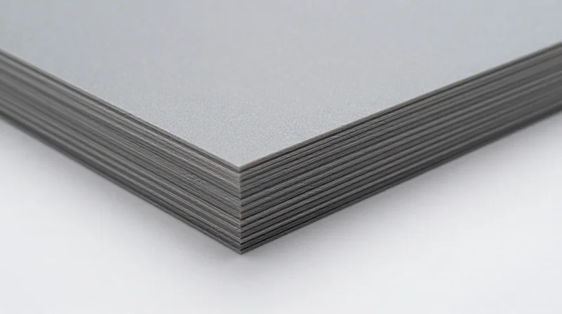
The Material Foundation of PTFE
Polytetrafluoroethylene (PTFE) laminates have long served as the backbone of aerospace and satellite RF engineering due to their exceptional dielectric properties. At the molecular level, the carbon-fluorine bond provides a stable, low-loss environment for high-frequency signals, effectively minimizing signal attenuation in the Ku and Ka-band ranges. By utilizing a fluoropolymer resin system often reinforced with ceramic fillers or woven glass fabrics, manufacturers can achieve precise control over the Dielectric Constant (Dk) and Dissipation Factor (Df), ensuring signal integrity across complex, multi-layered circuit designs.
Performance Metrics of Conventional PTFE Laminates
| Property | Typical PTFE Performance | Significance for Satellite |
|---|---|---|
| Dielectric Constant (Dk) | 2.1 to 3.5 | Low signal propagation delay |
| Dissipation Factor (Df) | < 0.002 | Minimized signal loss at high GHz |
| Thermal Stability | High | Resilience in vacuum/orbit |
Operational Challenges and Constraints
Despite its dominance, PTFE presents significant manufacturing hurdles that complicate the push toward miniaturization and higher integration. Its low surface energy necessitates specialized chemical treatments for copper adhesion, and the material's coefficient of thermal expansion (CTE) can be significantly mismatched with copper layers, leading to reliability concerns during thermal cycling in extreme satellite environments.
- Why is CTE matching difficult with PTFE?
PTFE has a high CTE compared to the copper foil used in circuitry. Under rapid thermal transitions common in LEO satellite orbits, this mismatch induces mechanical stress, which can lead to micro-cracking or pad lifting. - How does surface energy affect manufacturing?
PTFE is chemically inert with very low surface energy, preventing conventional chemical etching or plating processes from creating reliable bonds with copper, thus requiring costly plasma etching or specialized adhesion promoters. - Is PTFE suitable for high-density interconnects (HDI)?
The mechanical flexibility of standard PTFE can complicate high-density board fabrication, often requiring thicker substrates that limit the routing density compared to more rigid thermoset resin systems.
The Emergence of Ceramic-Filled High-Frequency Materials
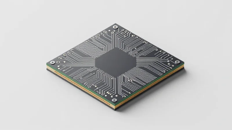
The Emergence of Ceramic-Filled High-Frequency Materials
As satellite communication transitions into V-band and beyond, the industry is increasingly moving away from pure PTFE substrates toward ceramic-filled composites. By integrating ceramic particles into a polymer matrix, engineers can precisely tune the dielectric constant (Dk) and minimize the coefficient of thermal expansion (CTE), addressing the structural limitations inherent in traditional soft-substrate materials.
Overcoming Mechanical Instability
Pure PTFE is notorious for its poor dimensional stability and high CTE, which can lead to interlayer registration errors and signal degradation under thermal cycling. Ceramic fillers act as a stabilizing agent, reinforcing the resin matrix to improve rigidity. This modification ensures that satellite phased-array antennas maintain precise structural integrity, even when subjected to the extreme temperature fluctuations of orbital deployment.
| Material Property | Pure PTFE | Ceramic-Filled Composite |
|---|---|---|
| Dimensional Stability | Low | High |
| Coefficient of Thermal Expansion (CTE) | High (Fluctuating) | Low (Stable/Controlled) |
| Dielectric Consistency | Excellent | Superior (Tunable) |
| Mechanical Rigidity | Poor | Excellent |
Frequently Asked Questions Regarding Ceramic Integration
- How does ceramic filling affect signal loss?
While traditional fillers might increase insertion loss, modern advanced ceramic fillers are engineered for low loss tangents, effectively maintaining the signal integrity profile synonymous with high-end PTFE performance. - Why is CTE control vital for V-band satellites?
At higher frequencies, even microscopic dimensional shifts in the PCB can cause significant phase errors; ceramic fillers mitigate these shifts to ensure consistent signal propagation. - Does ceramic content impact manufacturing?
Ceramic-filled laminates offer better processing compatibility with standard PCB fabrication techniques compared to pure PTFE, which often requires complex plasma etching for copper bonding.
Thermal Stability and CTE Challenges in Space
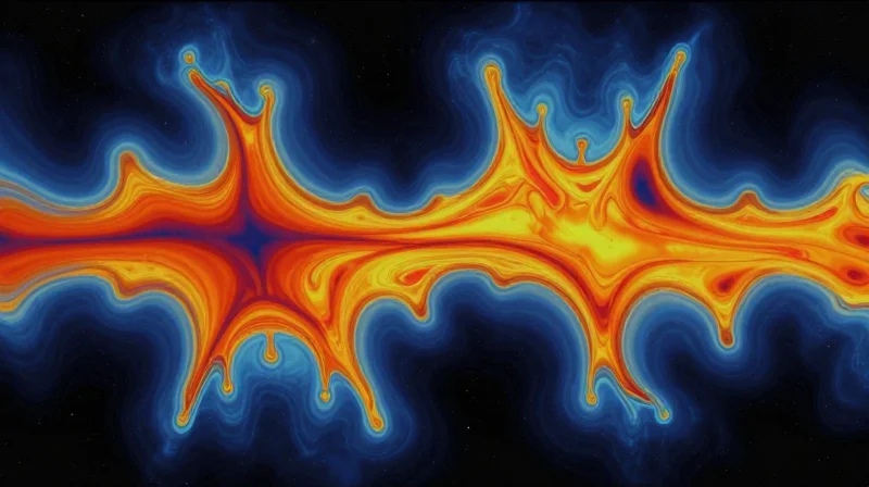
Thermal Stability and CTE Challenges in Space
In the vacuum of space, satellites encounter extreme thermal cycling, transitioning rapidly between intense solar radiation and deep-space cooling. This environment places immense stress on high-frequency PCBs, where the Coefficient of Thermal Expansion (CTE) becomes the primary arbiter of mechanical reliability. PTFE, while thermally stable in terms of its chemical structure, exhibits a significant CTE mismatch when compared to the copper cladding used in circuits, potentially leading to barrel cracking in vias and interfacial delamination.
Comparative Thermal Performance
| Parameter | PTFE-Based Laminates | Ceramic-Filled Composites |
|---|---|---|
| Z-Axis CTE | High (Non-linear) | Low (Controlled) |
| Dimensional Stability | Moderate | Excellent |
| Thermal Conductivity | Low | Moderate to High |
| Via Reliability | Sensitive to cycling | High resilience |
Ceramic-filled high-frequency materials address these challenges by reducing the Z-axis CTE to values closely matched with copper. This stability minimizes the mechanical tension exerted on plated through-holes (PTH) during the rapid expansion and contraction cycles inherent in orbital operations. By anchoring the polymer matrix with rigid ceramic particles, manufacturers can suppress the inherent movement of PTFE resins, ensuring signal path integrity over extended mission lifetimes.
- Why is Z-axis CTE critical for satellite hardware?
Vertical expansion causes the substrate to grow faster than the copper via, leading to fatigue fractures at the copper-to-pad interface during temperature swings. - How do ceramic fillers mitigate expansion?
Ceramic particles act as a mechanical constraint, significantly lowering the overall bulk CTE of the dielectric to more closely approximate the expansion rate of copper circuitry. - Does PTFE offer any advantages in thermal cycling?
PTFE remains highly flexible at cryogenic temperatures, which can prevent brittle failure in specific housing designs, though it lacks the rigid stability of ceramic composites.
Manufacturing and Fabrication Considerations
Processing Challenges in High-Frequency Fabrication
Fabrication efficiency is a deciding factor in satellite hardware production. PTFE materials, while electrically superior, present significant hurdles in standard PCB shops due to their soft, malleable nature and low surface energy. In contrast, ceramic-filled hydrocarbon or thermoset resins are engineered to behave more like traditional FR-4, significantly reducing the complexity of mechanical drilling and through-hole plating.
| Feature | PTFE-Based Laminates | Ceramic-Filled Materials |
|---|---|---|
| Drill Wear | High (soft/gummy) | Low to Moderate |
| Desmear Requirement | Plasma required | Chemical/Plasma |
| Plating Adhesion | Requires etching | High reliability |
| Mechanical Stability | Low (dimensional shift) | High (rigid) |
Critical Fabrication Considerations
- Why does PTFE require specialized drilling techniques?
PTFE is highly thermoplastic and prone to 'smearing' during mechanical drilling. The heat generated by drill bits can cause the material to flow into the hole, requiring aggressive plasma desmearing to ensure reliable copper-to-copper interconnection. - How do ceramic fillers simplify assembly?
Ceramic-filled materials exhibit higher rigidity and a tighter Coefficient of Thermal Expansion (CTE) match to copper. This reduces board warpage during reflow soldering and minimizes mechanical stress on surface-mount components. - Does plating adhesion differ between the two?
Yes. PTFE surfaces are naturally non-stick and require complex chemical etching or sodium naphthalene treatment to promote copper adhesion. Emerging ceramic-filled substrates often offer better native adhesion, resulting in more robust plated through-holes (PTH).
For satellite designers, the choice between these materials often hinges on a balance between performance requirements and production yield. While PTFE remains the gold standard for minimal dielectric loss in ultra-high-frequency bands, the move toward ceramic-filled technology is accelerating due to the lower cost of manufacturing and the increased reliability achieved through traditional, simplified fabrication processes.
Signal Integrity and Dielectric Consistency
Dielectric Consistency and Signal Integrity
In the context of Ka and V-band satellite communications, even microscopic fluctuations in the dielectric constant (Dk) can lead to significant phase errors and signal distortion. As frequencies push higher, the wavelength decreases, making the material's structural homogeneity a critical factor in performance. PTFE-based laminates traditionally struggle with Dk consistency due to the mechanical challenges of processing pure fluoropolymers, whereas modern ceramic-filled composites offer superior uniformity, effectively minimizing insertion loss and ensuring predictable signal propagation across complex array geometries.
Impact on Phase Stability
Phase stability is paramount for beamforming architectures in modern satellite payloads. When a dielectric material exhibits non-uniform Dk values, signals traveling through different parts of the same board experience varying propagation velocities, causing 'beam squint' and degraded array gain. Emerging high-frequency material technologies prioritize Dk tolerance control to ensure that phase relationships remain stable across the entire aperture, even under fluctuating temperature gradients typical of orbital environments.
| Parameter | PTFE-Based Laminates | Ceramic-Filled Composites |
|---|---|---|
| Dk Uniformity | Moderate/Variable | High/Superior |
| V-Band Performance | Prone to Dispersion | Optimized/Stable |
| Phase Accuracy | Affected by Dk drift | Highly predictable |
| Insertion Loss | Low at base, unstable | Very low and consistent |
Frequency-Specific Challenges
- How does Dk variance affect V-band designs?
At V-band frequencies, even minor fluctuations in substrate thickness or Dk homogeneity cause wavelength shifts that lead to phase mismatching, forcing designers to over-engineer correction circuits. - Why is material homogeneity critical for phased arrays?
Phased array performance relies on precise phase control at every antenna element; inconsistent materials introduce uncontrolled phase errors, which distort the signal beam and reduce overall link budget efficiency. - Can PTFE be improved to match modern standards?
Through the integration of engineered fillers, PTFE-based systems can achieve better mechanical stability and tighter Dk tolerances, though they often lag behind the inherent ceramic-filled material structures in pure phase consistency.
Cost-Performance Trade-off Analysis
Strategic Selection Criteria
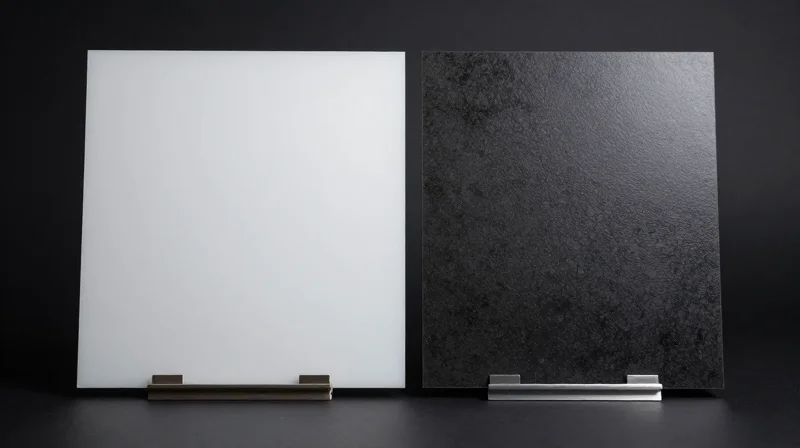
The decision to invest in advanced ceramic-filled materials over traditional PTFE hinges on a rigorous assessment of mission-critical requirements versus production scale. While PTFE remains the industry benchmark for affordability and ease of fabrication, its reliance on specific chemical treatments often introduces variability. Ceramic-filled substrates provide superior dielectric consistency and dimensional stability, which are essential for high-throughput Ka-band and V-band payloads where signal degradation leads to increased bit error rates.
| Feature | PTFE-Based Laminates | Ceramic-Filled Materials |
|---|---|---|
| Unit Cost | Low to Moderate | High Premium |
| Fabrication Complexity | Standard/Low | High/Specialized |
| Phase Stability | Moderate | Excellent |
| Thermal Reliability | Good | Superior |
Cost-Benefit Decision Matrix
- When is PTFE the optimal choice?
PTFE is preferred for constellations with large-scale production cycles where cost-per-unit is the primary driver and the operational environment is less thermally aggressive. - When is the premium for ceramic-filled substrates justified?
The extra cost is justified in high-value, long-duration missions requiring precise phase matching, ultra-low insertion loss, or environments with extreme thermal cycling that would otherwise cause traditional PTFE to deform or lose signal integrity. - Does material choice affect total program cost?
Yes; while ceramic-filled materials have a higher BOM cost, they often reduce total program risk by improving yield rates during testing and extending the operational lifespan of the satellite, effectively lowering the cost-per-bit over the mission's duration.
Future-Proofing Your Satellite Hardware
Strategic Material Selection for Longevity
As orbital lifespans extend and frequency bands push into the Q/V-band spectrum, the materials chosen today must account for thermal fatigue, ionizing radiation, and evolving modulation schemes. Future-proofing mandates a transition from reactive material selection to a predictive approach that treats PCB laminates as mission-critical structural components rather than mere interconnects.
| Parameter | Legacy PTFE Approach | Next-Gen Material Strategy |
|---|---|---|
| Frequency Scaling | Limited to Ka-Band performance | Optimized for W-Band and beyond |
| Thermal Stability | Requires periodic coefficient compensation | Near-zero CTE for high dimensional stability |
| Outgassing Risk | Standard vacuum testing | Advanced low-volatility certification |
Key Considerations for Hardware Designers
- How does moisture absorption impact long-term signal integrity?
PTFE can exhibit inconsistent dielectric constants if moisture is trapped; next-gen ceramic-filled laminates offer near-zero water absorption, ensuring signal stability throughout the multi-year orbital mission. - Why is Coefficient of Thermal Expansion (CTE) critical for satellite hardware?
Rapid thermal cycling in orbit causes mechanical stress at via interfaces; selecting materials with CTE matched closely to copper ensures reliable interconnects over thousands of thermal cycles. - Should designs prioritize standard PTFE to reduce upfront risk?
While standard PTFE lowers initial manufacturing hurdles, it may limit the hardware's frequency agility; emerging materials offer a wider design margin that future-proofs the payload against evolving throughput requirements.
Ultimately, the strategic move is to decouple RF front-end design from static material constraints. By adopting hybrid stack-ups—utilizing high-frequency performance laminates where signal integrity is paramount and standard substrates for power distribution—designers can achieve a balanced, cost-effective architecture that remains operational throughout the satellite's entire service life.
Choosing the right substrate is no longer just a design preference; it is a critical factor in the success of the next generation of global space communication. While PTFE remains a cornerstone of the industry, ceramic-filled materials offer distinct advantages for the higher-frequency challenges of tomorrow. Contact our engineering team today to review your project requirements and select the optimal material for your mission.
