In the world of electronics, the humble 2.2uF capacitor plays a vital yet often unseen role. From smoothing power supplies to shaping audio signals, this small component is crucial to countless circuits. In the same way that a well-placed water reservoir (capacitors) can control water flow, electronic capacitors control current flow. This article delves into the intricacies of the 2.2uF capacitor, exploring its various types, applications, and selection criteria to improve performance for your electronic project. Think of this as your in-depth exploration of 2.2uF capacitors, a critical component in modern electronics.
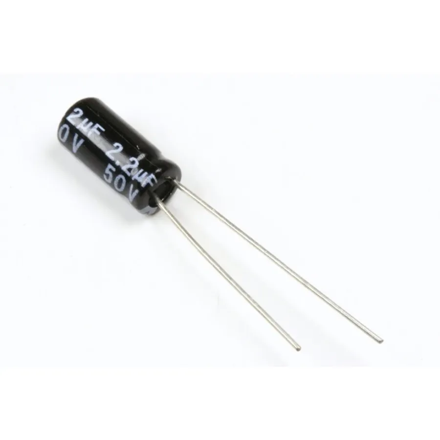
A 2.2uF capacitor is a fundamental electronic component characterized by its ability to store electrical energy in an electric field, measured in microfarads (µF), and resist changes in voltage. It's a crucial element in a wide variety of electrical circuits, performing functions like filtering, energy storage, and timing.
The '2.2uF' designation indicates the capacitor's capacitance, which quantifies its ability to store charge. This value is not merely an arbitrary number; it represents a specific capacity essential for achieving desired circuit behavior. Capacitance, measured in Farads (F), is often encountered in submultiples like microfarads (µF) due to the typically small charge storage capacity of practical capacitors. A 2.2µF capacitor stores 2.2 x 10^-6 coulombs of charge per volt applied across its terminals.
| Parameter | Description |
|---|---|
| Capacitance | The ability to store electrical charge. Measured in Farads (F), typically microfarads (µF) for practical capacitors. |
| Unit of Measure | Microfarad (µF). 1 µF = 1 x 10^-6 Farads |
| Role in Circuits | Used for filtering, energy storage, signal coupling, timing circuits and many more. It resists changes in voltage, making it useful for smoothing power supply fluctuations and blocking DC signals while passing AC. |
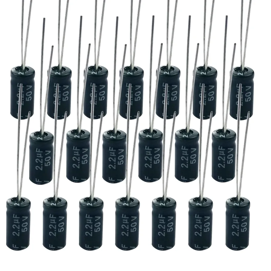
2.2uF capacitors are fundamental components in electronic circuits, available in various types distinguished by their construction and material properties. These variations directly influence their performance characteristics and suitability for different applications. The primary types include ceramic, electrolytic (radial), Mylar, and film capacitors.
| Capacitor Type | Material | Construction | Key Characteristics | Typical Applications |
|---|---|---|---|---|
| Ceramic | Ceramic Dielectric | Multilayer or Single-layer | Small size, low cost, stable with temperature variations | General purpose, bypass capacitors, decoupling |
| Electrolytic (Radial) | Aluminum or Tantalum Oxide | Electrolyte impregnated in a paper or film | High capacitance, polarized, can be sensitive to temperature and frequency | Power supplies, filtering, energy storage |
| Mylar | Polyester Film (Mylar) | Layered thin film | Good temperature stability, low cost, relatively large size | General purpose, audio coupling, timing circuits |
| Film | Various polymer films (e.g., polypropylene, polyester) | Layered thin film | High precision, high stability, low losses, good for audio applications | Precision circuits, audio equipment, high frequency circuits |
Ceramic 2.2uF capacitors are characterized by their small physical size and stability, making them a widely used general purpose capacitor. They utilize ceramic materials as their dielectric, which allows them to function efficiently across a wide range of temperatures with minimal performance fluctuations.
Electrolytic 2.2uF capacitors are known for providing a higher capacitance value in a smaller physical form factor. These capacitors use an electrolyte (liquid or solid) as one of their electrodes. A crucial characteristic is their polarity, meaning they must be connected correctly in a circuit to avoid damage or failure. Their uses include filtering and smoothing in power supplies.
Mylar and film 2.2uF capacitors offer enhanced precision and stability compared to ceramic capacitors. Mylar capacitors, using polyester film, are a cost-effective choice for many applications. Film capacitors, available with various polymer dielectrics (polypropylene, polyester, etc), provide excellent performance for critical applications, such as audio circuits, where low signal loss and signal integrity is a priority. Precision film capacitors, often with a 1% tolerance, are sought after where accuracy is paramount.
Ceramic 2.2uF capacitors are characterized by their compact size, stability, and cost-effectiveness, making them a versatile choice for numerous electronic applications. Their construction involves ceramic dielectric materials, which provide excellent temperature stability and low equivalent series resistance (ESR), contributing to their reliable performance in diverse circuits.
These capacitors are particularly suitable for applications where space is limited and high-frequency performance is crucial. Their inherent stability ensures consistent operation, even under varying environmental conditions, making them a preferred component in modern electronic designs. The following sections will outline their features, common applications, and key considerations when selecting ceramic 2.2uF capacitors.
| Feature | Description |
|---|---|
| Size | Extremely compact, suitable for space-constrained designs. |
| Stability | Excellent temperature stability and low ESR. |
| Cost | Relatively inexpensive, making them suitable for mass production. |
| Frequency Performance | Good high-frequency response due to low parasitic inductance. |
| Construction | Consists of ceramic dielectric materials, with metal electrodes. |
Electrolytic 2.2uF capacitors are characterized by their relatively high capacitance per unit volume compared to other types, achieved through the use of a liquid or gel electrolyte. This characteristic makes them suitable for applications requiring significant energy storage or filtering in a compact space. A key consideration when using electrolytic capacitors is their polarity; they must be connected correctly in the circuit to avoid damage or failure.
| Feature | Description |
|---|---|
| Capacitance Range | Moderate to High (2.2uF is in the lower end of range for electrolytic) |
| Polarity | Polarized; Requires correct orientation in the circuit. |
| Size | Relatively small for given capacitance, compared to film capacitors of the same capacitance |
| Cost | Generally lower cost compared to other capacitors like film type, especially at high capacitance |
| Operating Temperature | Moderate (specific temperature range varies by type) |
| Lifespan | Finite, Electrolyte can degrade over time, leading to reduced capacity |
| Accuracy | Typically less accurate; higher tolerance (e.g. +/- 20%) |
Typical applications for 2.2uF electrolytic capacitors include power supply filtering, where they help smooth out voltage fluctuations, and coupling/decoupling applications in lower-frequency circuits. They are also commonly used in audio circuits, although not usually for critical signal path applications due to their non-ideal behavior at high frequencies. Specifically, due to their relatively large size for a 2.2uF value, they are most common in power supply applications. Despite their advantages, electrolytic capacitors have limitations, such as a defined lifespan and higher equivalent series resistance (ESR) compared to film or ceramic capacitors, and considerations should be made when designing for long-term or high-frequency operation.
Mylar and film capacitors, including polyester film capacitors, are favored for applications demanding high precision, stability, and low losses. Their construction from thin layers of plastic film and metal electrodes results in excellent electrical characteristics, making them a preferred choice for audio circuits and other precision applications.
The advantages of Mylar and film capacitors are notable, which lead to their widespread use. Key advantages include:
Within the realm of audio applications, precision audio capacitors with a 1% tolerance are specifically selected for their ability to maintain signal integrity. By minimizing signal distortion and ensuring accurate frequency response, these capacitors deliver the highest possible audio fidelity. This makes them indispensable in high-end audio systems, where even slight deviations in component performance can become noticeable to the listener.
Key parameters to consider when specifying a Mylar or film capacitor include the voltage rating, temperature coefficient, and specific dielectric material (e.g., polypropylene, polyester). Understanding these factors is essential in selecting the most suitable capacitor for specific applications.
Selecting the appropriate 2.2uF capacitor requires a thorough understanding of its key specifications. These parameters dictate the capacitor's performance, reliability, and suitability for specific applications. Ignoring these specifications can lead to circuit malfunction or failure. Key considerations include voltage rating, temperature rating, tolerance, polarity, and dissipation factor.
| Specification | Description | Impact on Performance |
|---|---|---|
| Voltage Rating | The maximum voltage the capacitor can withstand without damage. It is essential to select a capacitor with a voltage rating higher than the maximum voltage expected in the circuit. | Exceeding the voltage rating can cause capacitor failure, leading to short circuits or reduced lifespan. The voltage rating must be at least equal or greater than the maximum voltage that may be encountered in the circuit. |
| Temperature Rating | The operational temperature range within which the capacitor will function correctly. Capacitors have minimum and maximum operating temperatures and should be selected according to the environment of the circuit. | Operating a capacitor outside of its rated temperature range can lead to decreased performance, reduced lifespan, or permanent damage. The temperature rating of the capacitor must be within the maximum and minimum temperature that the circuit will be exposed to. |
| Tolerance | The permissible deviation of the actual capacitance from its nominal 2.2uF value. Tolerance is typically expressed as a percentage. | Higher tolerance capacitors can affect circuit accuracy in sensitive applications. Capacitors with tight tolerances are often used in precision applications and must be taken into account in the overall circuit design. |
| Polarity | Whether the capacitor has a defined positive and negative terminal, such as in electrolytic capacitors. Polarized capacitors must be installed correctly to avoid damaging the capacitor. | Incorrectly connecting polarized capacitors in a circuit can result in immediate failure of the component, causing the capacitor to potentially explode, leading to damage of the circuit. |
| Dissipation Factor (DF) | A measure of energy loss in the capacitor, typically expressed as a percentage or tan δ. A lower dissipation factor indicates lower losses. | A high dissipation factor can cause the capacitor to heat up and reduce its efficiency, leading to undesirable losses in signal strength or power. Select capacitors with lower dissipation factor for high-frequency applications. |
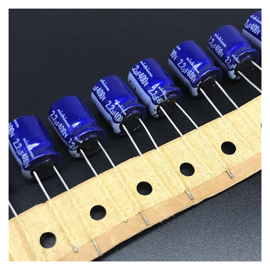
The 2.2uF capacitor, a component designed to store electrical energy, plays a crucial role in a variety of electronic circuits due to its specific capacitance value. Its applications range from filtering and decoupling to timing and energy storage, and it's particularly prevalent in areas like power supplies, audio circuits, and signal processing.
| Application Area | Function of 2.2uF Capacitor | Reason for 2.2uF Value |
|---|---|---|
| Power Supplies | Filtering and decoupling | Provides adequate filtering for common voltage fluctuations and noise. |
| Audio Circuits (Tweeters) | High-pass filtering | Precisely attenuates low frequencies, protecting tweeters. |
| Signal Processing | Frequency shaping and timing | Offers the specific capacitance value for circuit timing or frequency characteristics. |
In electronic circuit design, the precise value of a 2.2uF capacitor is often crucial, but situations may arise where a direct replacement is not readily available, necessitating the use of equivalent or substitute components. Understanding when and how to safely deviate from the specified capacitance value is essential to avoid circuit malfunction or damage.
The primary consideration when substituting a capacitor is its capacitance, measured in microfarads (uF). While a 2.2uF capacitor is a specific value, there are circumstances under which using a slightly different value might be acceptable. The following sections detail the implications of using higher or lower capacitance values, and when such substitutions are viable.
When substituting capacitors, particularly in critical circuits like filters, it's crucial to consider the overall impedance and frequency response characteristics. Capacitors in series have a combined capacitance (C_total) calculated as 1/C_total = 1/C1 + 1/C2 + ... + 1/Cn. If a specific capacitance is needed, you can calculate the series of capacitors needed to achieve the target value. For capacitors in parallel, the combined capacitance is simply the sum of individual capacitances, i.e., C_total = C1 + C2 + ... + Cn.
| Substitution Type | Capacitance Value | Impact on Circuit | Application Considerations |
|---|---|---|---|
| Higher Capacitance | > 2.2uF | Lower resonant frequency in filters; increased energy storage in power circuits; can lead to slower response times. | Acceptable in decoupling or smoothing applications with some leeway. Care needed in resonant circuits. |
| Lower Capacitance | < 2.2uF | Higher resonant frequency in filters; decreased energy storage; potentially faster response times. May lead to reduced signal strength or increased noise. | Use with caution; may lead to circuit malfunction if too much below 2.2uF, can be used in timing circuits. |
| Equivalent Circuit | Combination of components | Can achieve equivalent electrical performance to 2.2uF. Requires careful design. | Used in specific circuits where a single component substitution is not feasible, can be time consuming and costly. |
The tolerance of a capacitor is also an important factor. A capacitor with a ±10% tolerance could have a value ranging from 1.98uF to 2.42uF. Substituting a capacitor within this range is generally acceptable in most non-critical applications, but it is crucial to consider the effect of this variation on the circuit's overall performance.
When working with substitute capacitors, careful consideration should always be given to the voltage rating of the new capacitor to ensure that it meets or exceeds the voltage requirement of the original 2.2uF capacitor. Failing to do so may result in the new capacitor failing or causing damage to the circuit.
Sourcing 2.2uF capacitors requires careful consideration of both reliability and specific needs. A variety of vendors offer these components, each with their strengths. This section guides you through selecting reputable suppliers and the factors influencing your choice, ensuring you procure components that meet your project's requirements.
When selecting a supplier, consider the following factors to ensure you get the right 2.2uF capacitor for your application. Firstly, verify the component's authenticity and reputation by cross-referencing with datasheets, and reading customer reviews. Check the supplier's shipping times and costs to see if it fits your timeline and budget. Lastly, evaluate the support services provided by the supplier, as this is particularly crucial in the event of defects or the need for detailed technical queries.
This section addresses frequently asked questions about 2.2uF capacitors, providing concise and informative answers to common queries regarding their usage, specifications, and alternatives. The goal is to clarify any confusion and provide practical guidance for selecting and using these components effectively.
The 2.2uF capacitor, a seemingly simple component, is integral to countless electronic applications. Understanding its different types, specifications, and uses is essential for engineers and hobbyists alike. Whether you're designing a high-fidelity audio system or a stable power supply, selecting the right 2.2uF capacitor is crucial for optimal circuit function. The technology of the capacitor has greatly increased our productivity, but also has many areas that can be explored. Think about the next-generation applications of capacitors with even higher specifications and the impact on the electronics industry.

