In our increasingly electronic world, safety components like the fusible resistor play a critical role in preventing damage and hazards. Just like a safety valve in a pressure cooker prevents explosions, a fusible resistor protects delicate electronic circuits from the dangers of excessive current. This article demystifies the fusible resistor, exploring its working principle, applications, and crucial differences from other protective components.

A fusible resistor is a specialized type of resistor designed to act as a safety device within an electrical circuit. Unlike standard resistors, which primarily serve to control current flow and generate heat, a fusible resistor is engineered to intentionally fail by opening the circuit when exposed to excessive current. This controlled failure mechanism protects sensitive electronic components from damage caused by overcurrent conditions, making it an essential safety feature in various electronic devices.
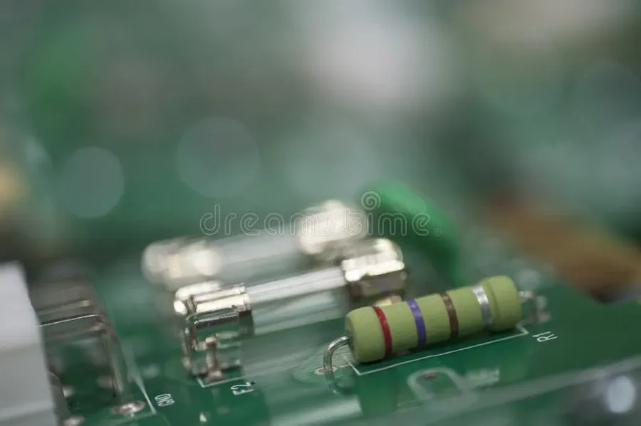
Fusible resistors are engineered to act as both a resistor and a safety device, protecting circuits from damage due to excessive current. Their functionality is rooted in the specific materials and construction that enable them to fail predictably when exposed to overcurrent conditions. Unlike standard resistors which are designed to maintain their resistance within specified limits, fusible resistors are intentionally designed to increase their resistance rapidly and ultimately open the circuit when a defined current threshold is exceeded. This controlled failure mechanism prevents further damage to the circuit.
The core principle of a fusible resistor's operation lies in the materials used for its resistive element. These materials have a carefully selected melting point. When the current flowing through the resistor increases beyond its rated capacity, the resistive element heats up. This heat is generated by the inherent resistance to the flow of electrons, according to Joule's Law (P = I²R), where P is power dissipated as heat, I is current, and R is resistance. As the current continues to rise, the temperature of the resistive element approaches and then reaches its melting point, causing the material to fuse, creating an open circuit and thus halting current flow.
The precise design of the fusible resistor dictates its performance characteristics, such as its resistance value, power rating, and the current at which it will fail, also known as the fusing current. The materials typically used in fusible resistors include metal alloys specifically chosen for their controlled melting point and resistivity properties. These might include mixtures of tin, lead, or other metals in specific proportions. The structure of the resistor, including the physical dimensions and the configuration of the resistive element, influences the distribution of heat and the speed with which the resistor will open the circuit under overcurrent conditions. The controlled manner in which a fusible resistor fails is a key difference from a standard resistor and essential for its safety role within the electrical circuit.
While both standard resistors and fusible resistors impede current flow, their primary purposes and failure mechanisms differ significantly. Standard resistors are designed to maintain a stable resistance under normal operating conditions, whereas fusible resistors are intentionally engineered to fail predictably under overcurrent conditions to protect the circuit, acting as a safety device rather than just a circuit element.
| Feature | Standard Resistor | Fusible Resistor |
|---|---|---|
| Primary Function | Limit current flow and provide a specified resistance. | Limit current and act as a safety device, interrupting the circuit under overcurrent. |
| Design | Typically constructed with a ceramic core, metal film or carbon composition, designed for stable operation. | Designed with a specific material and structure that will melt or break at a defined current level. |
| Materials | Metal alloys, carbon film, or metal oxide films that exhibit stable resistance. | Materials with a low and predictable melting point such as specific metal alloys, often with a ceramic core. |
| Failure Mode | Typically fails open or by changing resistance value due to overheating and component degradation. | Designed to fail open (break the circuit) by melting or fracturing to interrupt the current flow. |
| Current Rating | Typically specified by a power rating (watts), which is the maximum power the resistor can dissipate without damage. | Specified by a combination of resistance value and a maximum current value at which the resistor will fail. |
| Safety Role | No inherent safety role; primarily a circuit component. | Integral safety component, prevents damage from overcurrent. |
| Application | General circuit applications, setting bias points, load circuits and controlling current. | Used in safety-critical applications, in power supplies, and protection circuits to prevent damage from overcurrent events. |
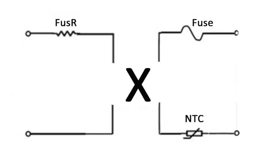
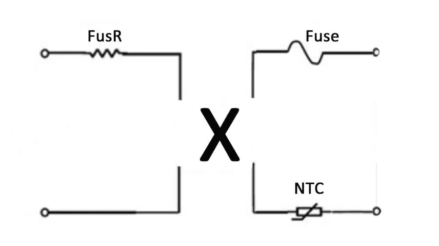
While both fusible resistors and fuses serve as overcurrent protection devices, they differ significantly in their construction, operation, and application. Fusible resistors combine the function of a resistor with the protective feature of a fuse, whereas fuses are dedicated overcurrent protection devices without intended resistive properties.
| Feature | Fusible Resistor | Fuse |
|---|---|---|
| Primary Function | Overcurrent protection and current limiting | Overcurrent protection |
| Structure | Resistor body with a designed weak point | Thin wire or metal strip with a low melting point |
| Resistance | Offers a specific resistance value | Ideally offers near zero resistance during normal operation |
| Failure Mode | Increase in resistance, followed by an open circuit | Melts and creates an open circuit |
| Response Time | Slower response time than a fuse, limited by heat generation | Fast response time, ideal for rapid overcurrent events |
| Accuracy | Less precise in terms of overcurrent threshold | More precise overcurrent threshold |
| Current Rating | Lower, usually up to a few amperes | Higher, from milliamperes to hundreds of amperes |
| Applications | Lower power circuits, power supplies, consumer electronics | High power circuits, industrial systems, automotive systems |
| Cost | Typically more expensive than fuses, due to dual functionality | Typically less expensive than fusible resistors |
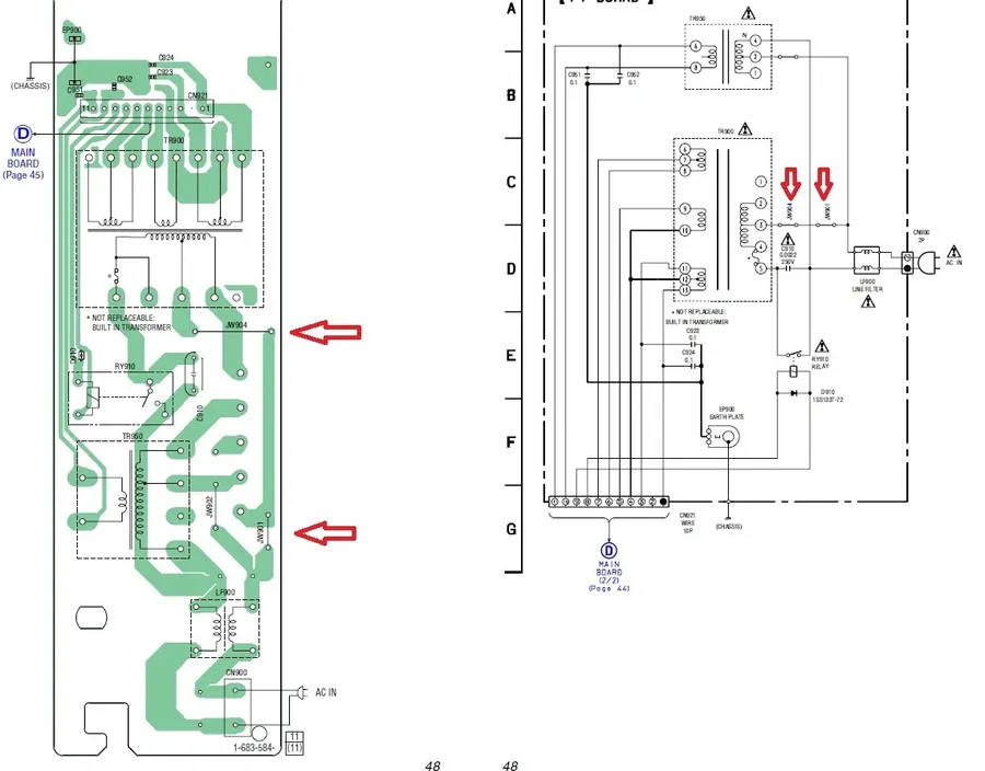
Fusible resistors are critical safety components in various electronic systems, designed to protect circuits from damage due to overcurrent conditions. Their specific characteristics make them particularly well-suited for applications where both circuit protection and some level of resistance are required.
Here's a breakdown of common applications:
In each of these applications, fusible resistors offer a crucial balance between normal circuit operation and a fail-safe mechanism. They provide a reliable and cost-effective way to protect valuable electronic components from the potentially destructive effects of electrical faults.
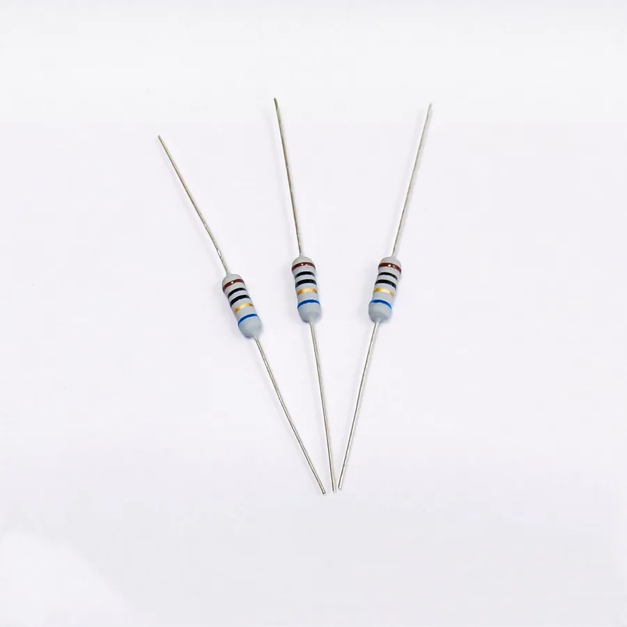
Identifying a fusible resistor requires careful observation of its physical characteristics and markings, which often differentiate it from standard resistors. While they may appear similar, key visual cues and specific markings can help in accurate identification. These components are specifically designed to fail safely under overcurrent conditions, so knowing how to spot them is crucial for proper circuit maintenance and troubleshooting.
This section addresses common inquiries regarding fusible resistors, providing clear and concise answers to help users understand their function, identification, and application.

Selecting the appropriate fusible resistor is crucial for ensuring both circuit protection and proper operation. This guide outlines the key parameters to consider when choosing a fusible resistor, including resistance value, wattage, current rating, tolerance, and physical size/package type. A careful assessment of these factors will ensure the chosen component effectively protects the circuit from overcurrent conditions.
| Parameter | Description | Importance |
|---|---|---|
| Resistance Value | The resistance in ohms (Ω) that the resistor provides under normal operating conditions. | Must match the intended circuit design; influences normal circuit operation. |
| Wattage Rating | The maximum power, in watts (W), the resistor can safely dissipate before failure. | Determines the amount of power the resistor can handle, should exceed expected power to ensure reliability and avoid premature failure. |
| Current Rating | The maximum current, in amperes (A), the resistor can withstand before it fuses. | Primary factor in overcurrent protection; must be below the maximum current the protected circuit can handle. |
| Tolerance | The permissible deviation of the actual resistance value from the stated value, expressed as a percentage (%). | Affects precision in circuit function; lower tolerance provides greater accuracy. |
| Physical Size/Package Type | The physical dimensions and construction of the resistor (e.g., axial, SMD, through-hole). | Must be compatible with the physical layout and manufacturing process of the circuit board. |
| Fusing Characteristics | The behavior of the resistor under overcurrent conditions, including the speed and method of fusing. | Ensures proper protection, must be quick and reliable to prevent damage to the circuit. |

Replacing a blown fusible resistor requires careful attention to detail to ensure the safety and proper operation of the circuit. This guide provides a step-by-step process for replacing a faulty fusible resistor, covering necessary precautions, tools, and verification steps.
Fusible resistors are a crucial yet often overlooked component in electronic circuit protection, safeguarding devices from potentially catastrophic overcurrent conditions. By understanding their unique properties and applications, we can make informed choices about using the appropriate safety mechanism. Whether you are a seasoned engineer or an electronics hobbyist, mastering the functionality of the fusible resistor is essential for ensuring the safety and longevity of your electronic projects. Next time a small component protects your circuit from a major failure, you may want to remember the unsung hero: the fusible resistor.

