In the realm of electronics, a resistor is as fundamental as a brick in a building. It's a humble component that provides the necessary 'resistance' to current flow, acting as an electrical traffic controller. This guide will unravel the mysteries of resistors, demonstrating how these essential building blocks of circuits impact our daily lives.

A resistor is a fundamental passive electronic component that impedes the flow of electrical current within a circuit. Its primary function is to introduce a specific amount of electrical resistance, thereby controlling current and voltage levels as dictated by Ohm's Law (V=IR), where V is voltage, I is current, and R is resistance. This crucial role enables the precise management of electrical energy within circuits.
The core concept of a resistor is electrical resistance. Resistance is a measure of how much a material opposes the flow of electric current. A higher resistance value means a greater impediment to current flow. Resistors achieve this by converting a portion of the electrical energy flowing through them into heat, a process known as Joule heating. This heat dissipation is an important consideration in the design of electronic circuits.
Ohm's Law provides the basic relationship governing the behavior of resistors in circuits. The law states that the current through a conductor between two points is directly proportional to the voltage across the two points and inversely proportional to the resistance of the conductor. Therefore, resistors are vital for controlling the current and voltage in a circuit. By manipulating resistance, designers can adjust current flow in electronic systems, ensuring components receive the proper current and voltage levels to perform their designated functions. The unit of resistance is the Ohm (Ω), typically measured with a multimeter.

Resistors, fundamental components in electronic circuits, come in various types, each tailored for specific applications. These types differ in construction, materials, performance characteristics, and suitability for various environments. Understanding these differences is essential for effective circuit design and implementation.
| Resistor Type | Construction | Typical Applications | Advantages | Disadvantages |
|---|---|---|---|---|
| Carbon Composition | Finely ground carbon mixed with a binder; molded into a cylindrical shape with leads | General-purpose applications, high-voltage circuits | High surge capability, relatively inexpensive | Higher noise, poor tolerance, unstable with temperature |
| Metal Film | Thin metal film deposited on a ceramic substrate; spiral cut to achieve resistance | Precision circuits, audio equipment | Good tolerance, low noise, stable with temperature | Lower surge capability, more expensive than carbon composition |
| Carbon Film | Thin carbon film deposited on a ceramic substrate; spiral cut to achieve resistance | General-purpose applications | Lower cost than metal film resistors | Less precise than metal film, higher noise, temperature sensitive |
| Wirewound | Resistive wire wound around a ceramic core; often coated for protection | High power applications, power supplies | High power rating, good precision, stable at high temperature | Inductive at high frequencies, large size |
| Surface Mount (SMD) | Small ceramic substrate with a thick film resistive element and termination pads | Compact electronic devices, PCB assembly | Small size, automated assembly, low parasitic inductance | Lower power handling, less robust than through-hole types |
The selection of a specific resistor type depends on the requirements of the application. Factors such as precision, power handling, temperature stability, and cost all need to be carefully considered. Furthermore, the physical size and mounting method of the resistor are crucial factors in PCB design.
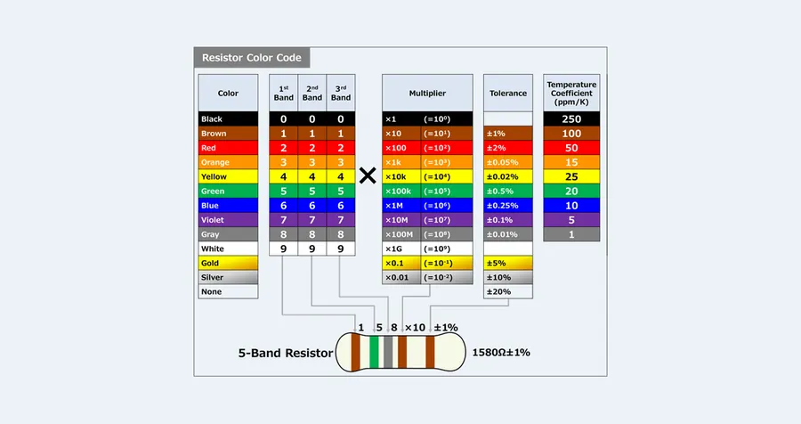
Resistor color codes are a standardized system used to indicate the resistance value, tolerance, and sometimes temperature coefficient of a resistor. These color bands, typically ranging from four to six, provide a quick visual method for identifying these crucial electrical characteristics, eliminating the need for physically measuring the resistor each time.
| Color | Digit | Multiplier | Tolerance |
|---|---|---|---|
| Black | 0 | 1 | ±20% |
| Brown | 1 | 10 | ±1% |
| Red | 2 | 100 | ±2% |
| Orange | 3 | 1,000 | ±0.05% |
| Yellow | 4 | 10,000 | ±0.02% |
| Green | 5 | 100,000 | ±0.5% |
| Blue | 6 | 1,000,000 | ±0.25% |
| Violet | 7 | 10,000,000 | ±0.1% |
| Grey | 8 | N/A | ±0.01% |
| White | 9 | N/A | N/A |
| Gold | N/A | 0.1 | ±5% |
| Silver | N/A | 0.01 | ±10% |
The color code is read from left to right, with the first band closest to the edge of the resistor. Each band represents a specific value or characteristic. For a 4-band resistor, the first two bands represent the first and second digits of the resistance value, respectively, while the third band is the multiplier, and the fourth band indicates the tolerance. A 5-band resistor uses the first three bands for the resistance value digits, the fourth as the multiplier and fifth as tolerance. 6-band resistors add a sixth band for the temperature coefficient. When reading the resistor, determine the reading direction by first identifying the tolerance band, usually gold or silver, which is often more widely spaced from the other bands.
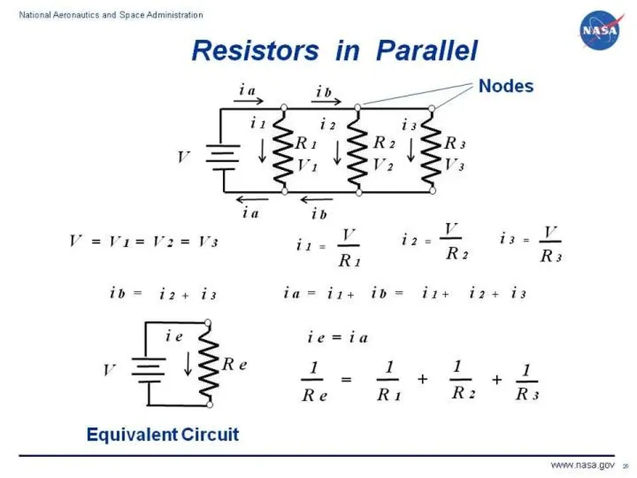
Resistors are fundamental components in electronic circuits, and their behavior changes when connected in series or parallel. Understanding these configurations is crucial for circuit analysis and design, as they determine how current and voltage distribute within the circuit. Series connections increase the overall resistance, while parallel connections decrease it.
| Characteristic | Series Configuration | Parallel Configuration |
|---|---|---|
| Total Resistance | R_total = R1 + R2 + R3 + ... | 1/R_total = 1/R1 + 1/R2 + 1/R3 + ... |
| Current | Same through each resistor | Divides among resistors, inversely proportional to resistance |
| Voltage | Divides among resistors, directly proportional to resistance | Same across each resistor |
In a series circuit, the same current flows through all resistors, and the total resistance is the sum of the individual resistances. Conversely, in a parallel circuit, the voltage across each resistor is the same, and the reciprocal of the total resistance is the sum of the reciprocals of the individual resistances.
The formulas provided in the table are essential for calculating the total resistance in each configuration. These calculations help in predicting the current and voltage behavior within the circuit, which is crucial for designing and troubleshooting electronic systems.
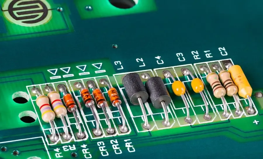
Resistors, fundamental components in electronic circuits, play a crucial role in various applications across diverse industries. Their primary function is to control current flow by impeding it, which is essential for proper operation of electrical systems. This section will delve into several common applications, explaining how resistors facilitate vital electronic functions.
These applications demonstrate the fundamental importance of resistors in circuit design. Their ability to precisely control current and voltage makes them indispensable across a wide spectrum of electronic devices.
Resistors, while fundamental to electronic circuits, are not ideal components; they dissipate electrical energy as heat. Understanding a resistor's power rating—the maximum power it can safely dissipate—and its temperature coefficient, which describes how its resistance changes with temperature, is crucial for circuit design to avoid component failure or performance degradation.
The power a resistor dissipates (P) is given by the formula P = I²R (where I is the current through the resistor and R is its resistance) or P = V²/R (where V is the voltage across the resistor). Exceeding the specified power rating can lead to overheating, permanent damage, or even catastrophic failure of the resistor. Therefore, selecting a resistor with an adequate power rating is paramount to ensuring the reliability and longevity of electronic circuits.
| Parameter | Description | Impact |
|---|---|---|
| Power Rating | Maximum power a resistor can dissipate safely | Exceeding rating leads to overheating, damage or failure |
| Temperature Coefficient | Change in resistance per degree Celsius (ppm/°C) | Impacts precision, especially in high-temperature environments |
| Operating Temperature | Temperature range where resistor operates normally | If exceeded can affect resistance value and life cycle of the resistor |
Temperature coefficients, typically expressed in parts per million per degree Celsius (ppm/°C), are critical in applications requiring precise resistance values over a range of temperatures. A high temperature coefficient means the resistance value will change more significantly with temperature fluctuations, potentially impacting circuit performance in sensitive applications such as precision measurement or amplification circuits. Resistors are often specified with a temperature range over which they can operate within their specified rating.
When selecting a resistor for a specific application, it is advisable to choose a resistor with a power rating significantly higher than the calculated power dissipation. As a general rule of thumb, derating the resistor by 50% is a safe approach. For example, if a circuit is calculated to dissipate 0.25W, using a 0.5W or 1W rated resistor is recommended to provide a safety margin, ensure reliable operation, and extend the component's lifespan. In addition, it's crucial to consider the operating temperature, especially in high-temperature environments where derating becomes even more important.
This section addresses frequently asked questions about resistors, providing clear and concise answers to common queries and misconceptions about these fundamental electronic components. The following answers are based on fundamental electrical principles and aim to clarify the purpose, function, and characteristics of resistors.
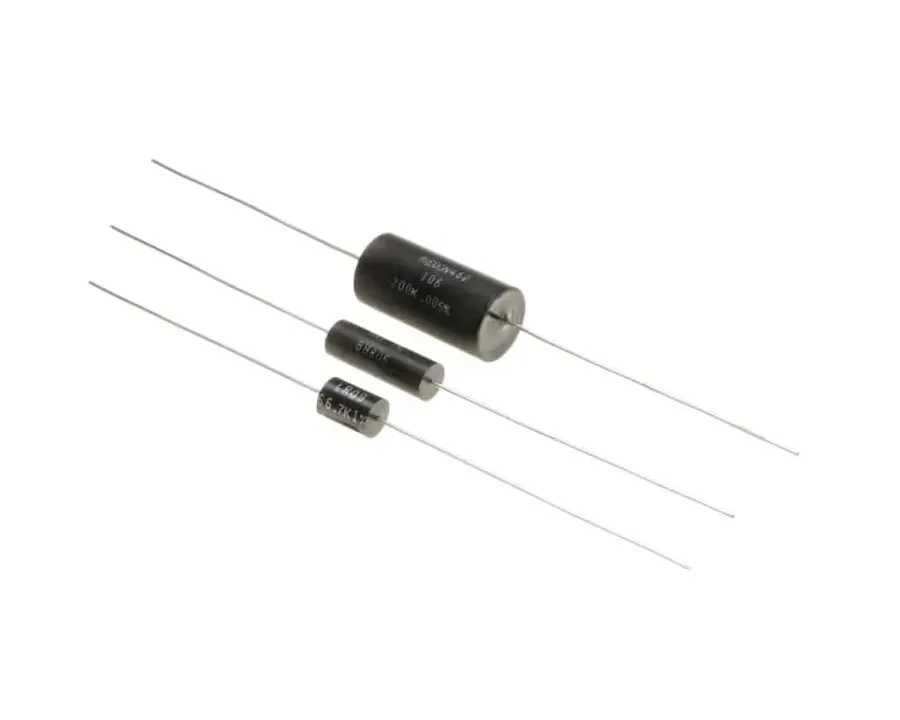
Beyond basic resistance, advanced applications require a nuanced understanding of resistor precision, tolerance, and specialized types. Precision resistors offer highly accurate resistance values, while tolerance dictates the permissible deviation from the nominal value. Special types of resistors, like thermistors, varistors, and photoresistors, exhibit unique responses to external factors, enabling sophisticated circuit functionalities.
| Feature | Precision Resistors | Standard Resistors |
|---|---|---|
| Tolerance | Typically 0.1% or less | Typically 1%, 5%, or 10% |
| Accuracy | Very high, precise resistance value | Less precise, resistance value can vary |
| Cost | Higher cost | Lower cost |
| Applications | Critical applications requiring high accuracy (e.g., measurement, instrumentation) | General applications where high accuracy is not essential |
Tolerance is a critical parameter indicating the allowable deviation from the stated resistance value. Common tolerance ratings include 5%, 1%, and 0.1%, with tighter tolerances corresponding to higher precision and, typically, higher cost. Selecting the appropriate tolerance is vital to ensure a circuit's performance within its design specifications. For instance, a resistor with a 100Ω nominal value and a 5% tolerance can have an actual resistance ranging from 95Ω to 105Ω, which may not be acceptable in all applications.
The selection of special resistors often depends on the specific environmental conditions and circuit requirements. For example, a thermistor is ideal for monitoring temperature in a sensitive piece of medical equipment, while a varistor can protect against transient high-voltage spikes in industrial power supplies. The diverse range of special resistors expands the possibilities in electronic circuit designs.
Resistors are vital components in the world of electronics, shaping circuits with their ability to limit current flow. Understanding the function, types, and applications of resistors is crucial for anyone working with or interested in electronics. From basic LED circuits to complex power management systems, the humble resistor plays a pivotal role in shaping our technological world. Continued exploration of resistor technology will pave the way for more efficient and powerful electronic solutions.

