SMD resistors, the unsung heroes of modern electronics, are integral to the functionality of virtually every electronic gadget we use. From smartphones to complex industrial machinery, these tiny components regulate current flow and ensure precise operation. This article will navigate the intricacies of SMD resistors, exploring their types, coding systems, and practical applications, bridging the gap between technical jargon and everyday understanding.
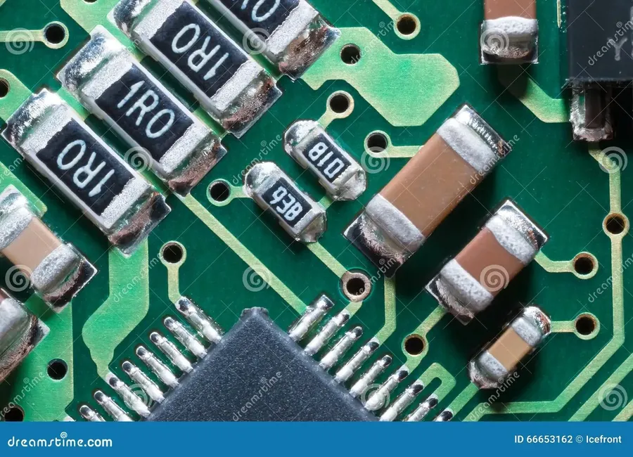
Surface Mount Device (SMD) resistors are a type of electronic component designed for direct mounting onto the surface of a printed circuit board (PCB), contrasting with through-hole components that have leads inserted into holes in the board. This technology is a cornerstone of modern electronics due to its high degree of automation in manufacturing and reduction in size. SMD resistors provide precise electrical resistance, a fundamental property used in electronic circuits to control current and voltage.
The primary purpose of an SMD resistor, like any other resistor, is to impede the flow of electrical current, converting some electrical energy into heat as the current passes through. This controlled resistance is essential for numerous functions within circuits, such as setting voltage levels, limiting current, creating specific signal paths and generating heat for thermal management. The advent of surface mount technology (SMT), in which SMD components such as resistors are used, revolutionized electronics manufacturing due to its efficiency and miniaturization advantages. Before SMT, components had leads that required through-holes in the circuit board which led to less dense and higher cost production, also limiting the speed of assembly. SMT eliminated this need allowing for smaller and higher density boards, faster automated assembly and overall reduction of production costs.
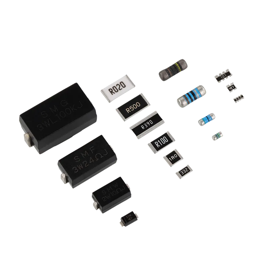
SMD resistors are not monolithic; they are manufactured using different technologies each offering specific performance characteristics. The three primary types are thick film, thin film, and metal foil resistors, each distinguished by their construction and resulting properties.
| Type | Construction | Tolerance | Temperature Coefficient (TCR) | Noise Level | Cost |
|---|---|---|---|---|---|
| Thick Film | Conductor paste screen-printed onto a ceramic substrate. | Generally 1% to 5% | Typically ±100 to ±250 ppm/°C | Moderate | Low |
| Thin Film | Thin film of resistive material deposited onto a substrate. | 0.1% to 1% | Typically ±25 to ±100 ppm/°C | Low | Moderate |
| Metal Foil | Resistive material made of a metal foil. | Up to 0.005% | Extremely low, ±1 to ±5 ppm/°C | Very Low | High |
The selection of a resistor type depends critically on the specific application requirements, balancing cost against performance factors like precision, thermal stability, and noise. For example, precision analog circuits may necessitate thin or metal film resistors for their superior tolerance and low noise, while general-purpose applications may find thick film resistors sufficient.
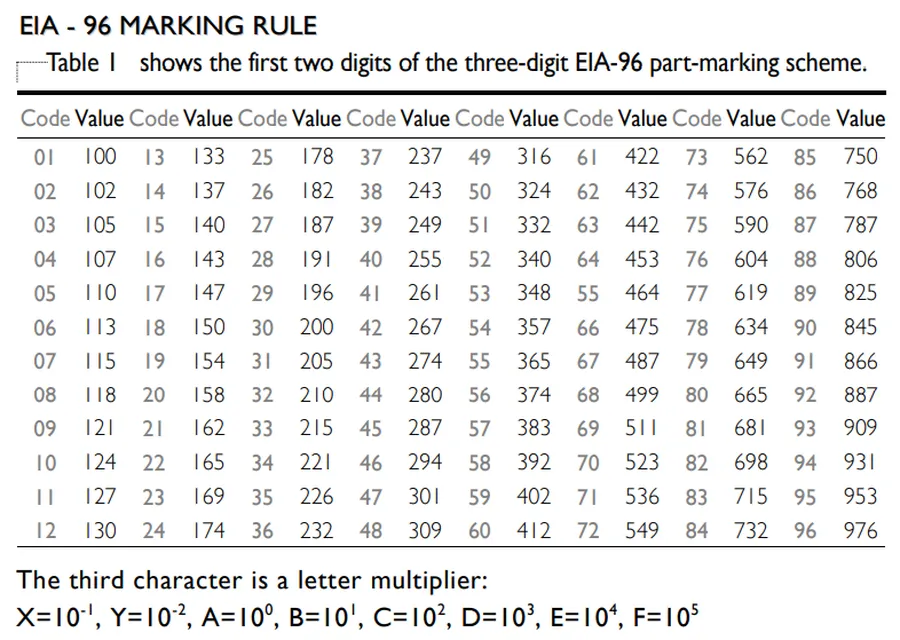
Surface Mount Device (SMD) resistors utilize a compact coding system to indicate their resistance values, a crucial aspect for circuit design and repair. These codes, typically 3-digit, 4-digit, or EIA-96, are essential for determining the component's ohmic value without explicit printed numbers. Understanding these codes allows for quick identification and selection of SMD resistors in electronic assemblies.
SMD resistor coding primarily uses numerical and sometimes alphabetical characters to encode the resistance value. The system often employs a multiplier concept, where digits represent the base value and another digit indicates a power of ten multiplier. This coding system is a space-saving method used widely in the electronics industry.
| Code Type | Description | Examples | Calculation |
|---|---|---|---|
| 3-Digit Code | Two significant digits followed by a multiplier. The multiplier represents a power of 10. | 102, 473, 221 | 102 = 10 * 10^2 = 1000 Ω (1 kΩ), 473 = 47 * 10^3 = 47000 Ω (47 kΩ), 221 = 22 * 10^1 = 220 Ω |
| 4-Digit Code | Three significant digits followed by a multiplier. The multiplier represents a power of 10. | 1002, 4703, 2201 | 1002 = 100 * 10^2 = 10000 Ω (10 kΩ), 4703 = 470 * 10^3 = 470000 Ω (470 kΩ), 2201 = 220 * 10^1 = 2200 Ω |
| EIA-96 Code | Uses a two-digit number and a letter to define resistance value. The two-digit number is the base, and the letter is the multiplier. | 01A, 20C, 96B | 01A = 100 * 10^0 = 100 Ω, 20C = 158 * 10^2 = 15800 Ω (15.8 kΩ), 96B = 976 * 10^1 = 9760 Ω (9.76 kΩ) |
For the EIA-96 system, a table or calculator is often needed as the numbers do not correspond directly to the resistance value. This system allows for 1% tolerance resistors to be identified. Refer to the EIA-96 standard for accurate conversions.
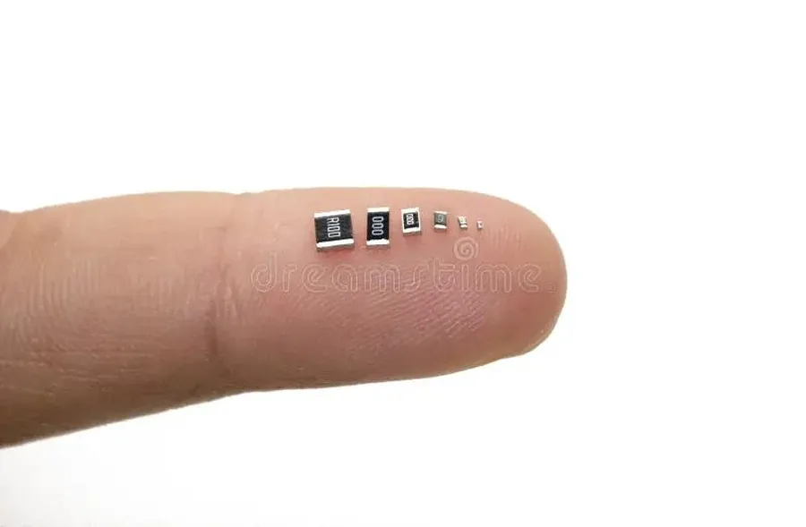
Surface Mount Device (SMD) resistors are available in standardized sizes, which are crucial for circuit board design and manufacturing. These sizes, typically represented by a four-digit code, directly influence the resistor's power handling capability, physical footprint, and suitability for different applications. Understanding these dimensions is essential for selecting the appropriate component for a given design.
| Size Code | Length (mm) | Width (mm) | Typical Power Rating (W) | Description |
|---|---|---|---|---|
| 0201 | 0.6 | 0.3 | 0.05 | Extremely small, used in space-constrained designs. |
| 0402 | 1.0 | 0.5 | 0.0625 | Small size, commonly used in compact devices. |
| 0603 | 1.6 | 0.8 | 0.1 | A good balance between size and power rating. |
| 0805 | 2.0 | 1.25 | 0.125 | Commonly used, good for manual soldering and prototyping. |
| 1206 | 3.2 | 1.6 | 0.25 | Larger size, better power handling. |
| 1210 | 3.2 | 2.5 | 0.5 | Wider footprint than 1206, used for higher power. |
| 1812 | 4.5 | 3.2 | 1.0 | Large size, ideal for higher power applications. |
| 2010 | 5.0 | 2.5 | 0.75 | Wider body for power disapation, used in some power applications. |
| 2512 | 6.3 | 3.2 | 1.0 | Large size for high-power dissipation and special requirements. |
The dimensions provided are nominal; tolerances exist in manufacturing processes. As the size of the resistor increases, so does its physical size and its ability to dissipate more power. The 0201 package is one of the smallest available, and while its tiny footprint is excellent for miniaturization, its power handling capabilities are also quite small. Conversely, a 2512 resistor has the largest footprint of the standard sizes, allowing for higher power dissipation. Size selection must also consider the manufacturability aspect, with larger package sizes generally more friendly for manual soldering and prototyping.
Selecting the correct size involves tradeoffs between space, power handling, and manufacturability. For example, if the designer is working on a small portable electronic device where space is limited, choosing a smaller size such as 0402, may be necessary but power needs must also be considered. Conversely, a power supply may use a larger package to ensure that the component does not overheat. It is crucial to balance the size and the requirements of the circuit.
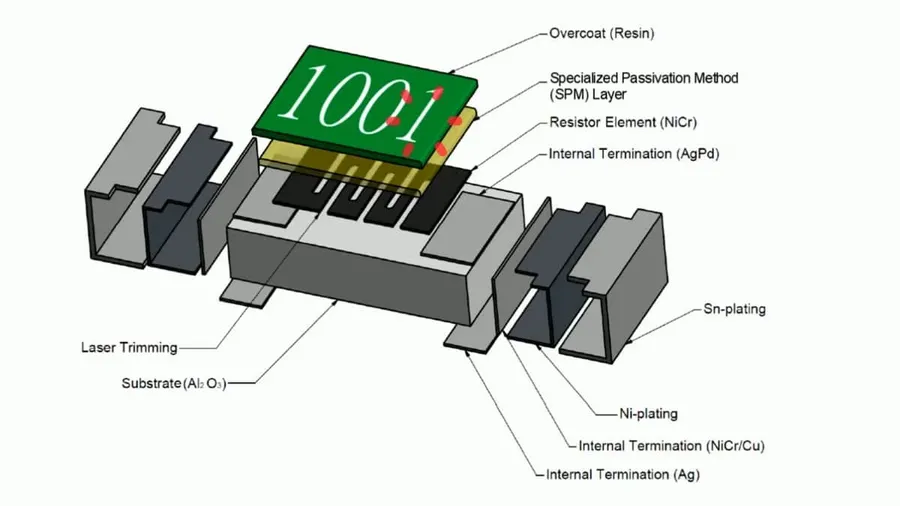
The performance and reliability of SMD resistors are intrinsically linked to the materials and construction methods employed. These components, designed for surface mounting on circuit boards, utilize various materials and manufacturing processes to achieve specific electrical characteristics, with the choice of materials directly impacting temperature stability, resistance tolerance, and overall durability.
Key differences exist between thick and thin film construction techniques, which influence the precision and application of SMD resistors:
| Feature | Thick Film Resistors | Thin Film Resistors |
|---|---|---|
| Material Deposition | Screen-printed paste containing conductive particles (typically metal oxides and glass frit). | Vacuum-deposited or sputtered film of conductive material (e.g., nickel-chromium, tantalum nitride). |
| Film Thickness | Relatively thick (micrometers). | Very thin (nanometers). |
| Resistance Tolerance | Typically wider tolerances (e.g., ±1% to ±5%). | Tighter tolerances (e.g., ±0.1% to ±1%). |
| Temperature Coefficient | Generally higher TCR (less stable with temperature). | Lower TCR (more stable with temperature). |
| Noise | May exhibit slightly higher noise levels. | Lower noise characteristics. |
| Cost | Lower cost to produce. | Higher cost due to the manufacturing complexity. |
| Applications | General purpose applications where high precision is not essential. | Precision applications, such as instrumentation, medical equipment, and high-fidelity audio. |
Beyond film type, other key material considerations include:
The interplay between these materials and construction methods determines the performance characteristics of an SMD resistor, making material selection a critical aspect of circuit design.
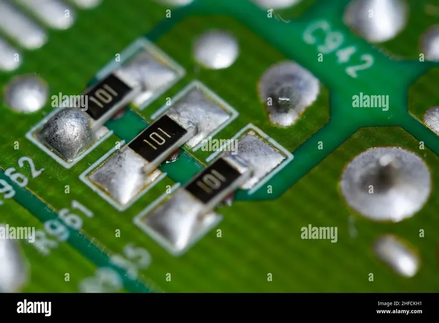
SMD resistors, owing to their compact size and versatile characteristics, are ubiquitous in modern electronics. They serve crucial functions in a diverse array of applications, from sensing and current limiting to heat dissipation. Their implementation across various devices underscores their importance in contemporary circuit design.
Selecting the appropriate SMD resistor for a specific application is crucial for optimal circuit performance and reliability. This process involves carefully considering several key parameters to ensure that the chosen component meets the demands of the design, and to avoid premature failure of the component. The selection process balances electrical requirements with physical constraints.
| Parameter | Description | Considerations |
|---|---|---|
| Resistance Value | The specific resistance in ohms required for the circuit. | Must match circuit design requirements; use Ohm's Law to verify. |
| Tolerance | The allowable percentage deviation from the nominal resistance. | Tighter tolerance for precision circuits, wider for general use. Critical for high accuracy applications. |
| Power Rating | The maximum power the resistor can safely dissipate in Watts. | Select a rating significantly higher than the predicted power dissipation, with a safety factor, to reduce component stress, and increase operational life span. |
| TCR | How resistance changes with temperature in ppm/°C. | Low TCR for stable resistance over temperature. Very important in precision measurement, and temperature sensing circuits. |
| SMD Size | Physical dimensions of the SMD package, for example 0603, 0805, 1206. | Consider board space and power requirements, smaller components provide limited power dissipation, select the largest suitable component. |
| Operating Temperature Range | The safe temperature operating limits of the component. | Consider the environment in which the component will operate, ensure the maximum operating temperature of the component exceeds the maximum ambient temperature. |
| Material | Material type, such as thick film, thin film, or metal foil. | Affects resistor properties. Metal film is generally better, but is more expensive. Thick film resistors are the lowest cost alternative. |
This section addresses common queries regarding SMD resistors, providing clear and concise answers to help you understand their characteristics, usage, and handling.
Effective troubleshooting of SMD resistor circuits requires a systematic approach to identify component failures. This section outlines common failure modes, diagnostic techniques, and testing procedures to ensure accurate identification and resolution of issues related to SMD resistors.
From deciphering obscure codes to implementing them in cutting-edge technology, the world of SMD resistors is both complex and fundamental. The proper understanding of SMD resistors is crucial for any modern electronic engineer. Whether you're a seasoned engineer or a hobbyist, grasp of these minute yet powerful components is essential for success in today's electronics-driven world. The continued development of SMD resistors ensures that our devices will continue to shrink while becoming evermore powerful.

