In the ever-evolving landscape of electronics, the humble capacitor plays a pivotal role, akin to a tiny energy reservoir. Among the vast array of capacitors, the 1000uF capacitor is a workhorse, often found in power supplies, audio amplifiers, and motor controls, to name just a few. Understanding the nuanced details of a 1000uf capacitor is crucial for both hobbyists and professionals alike. This article dives deep into the function, specifications, and diverse applications of these components. From the fundamental concepts to advanced techniques, we explore how a 1000uF capacitor functions and where it fits into the broader world of electronics, making the complex simple and the obscure clear, while connecting the theory to real-world uses.
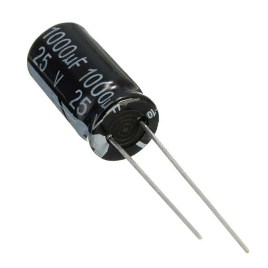
A 1000uF capacitor is an electrolytic capacitor characterized by its capacitance of 1000 microfarads (µF). Capacitance, measured in farads (F), quantifies a capacitor's capacity to store electrical energy in an electric field. The 1000µF rating signifies its relatively high charge storage capacity compared to lower value capacitors, typically used in applications where larger charge storage or filtering is required.
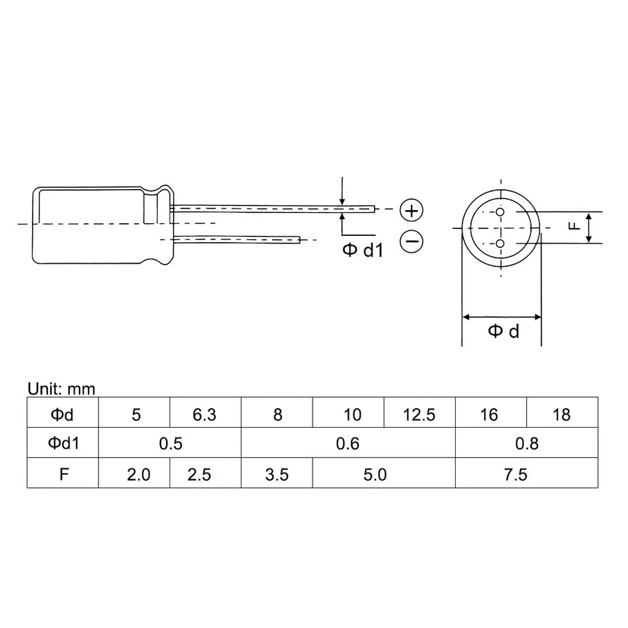
Beyond its 1000 microfarad (µF) capacitance, a 1000uF capacitor's performance is governed by several critical specifications, including its voltage rating, tolerance, operating temperature range, and Equivalent Series Resistance (ESR). These parameters are crucial for ensuring stable and reliable operation within electronic circuits.
| Specification | Description | Impact on Application |
|---|---|---|
| Capacitance | Measured in microfarads (µF), in this case, 1000µF. Indicates the amount of electrical charge the capacitor can store. | Determines the capacitor's ability to filter low-frequency signals and provide energy storage for power smoothing. |
| Voltage Rating | The maximum DC voltage the capacitor can safely withstand, e.g., 25V, 35V, or 50V. | Exceeding this can damage or destroy the capacitor; should always be greater than maximum circuit voltage. |
| Tolerance | The permissible deviation from the stated capacitance value, expressed as a percentage, such as ±20%. | Affects the precision of timing circuits, and needs to be factored into circuit design. |
| Operating Temperature Range | The temperature range within which the capacitor can function reliably. e.g., -40°C to +105°C | Extremes outside of this range can cause capacitance value and ESR to change and ultimately cause damage |
| Equivalent Series Resistance (ESR) | The internal resistance of the capacitor, affecting its ability to handle high-frequency signals. | Higher ESR can cause energy loss and heating, reducing the effectiveness of the capacitor, particularly in switching circuits. |
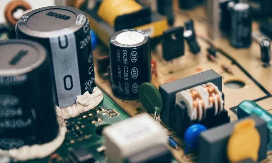
1000uF capacitors are versatile components widely employed in electronic circuits, primarily for filtering, smoothing power supply outputs, and providing temporary power during brief voltage drops. These capacitors play a critical role in ensuring the stability and reliability of electronic devices.
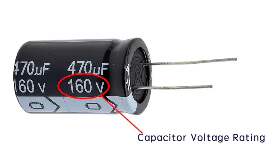
Selecting the appropriate voltage rating for a 1000uF capacitor is crucial for circuit reliability and safety. The capacitor's voltage rating, specified in volts (V), indicates the maximum voltage it can safely withstand without risk of failure or damage. Operating a capacitor beyond its rated voltage can lead to dielectric breakdown, causing short circuits, overheating, and potential component damage.
The golden rule is that the voltage rating of the chosen capacitor should always be equal to or greater than the maximum voltage expected in your circuit. It's better to have a safety margin, meaning the capacitor's rating should exceed the circuit's operating voltage by a reasonable amount, such as 20-30%, to handle voltage transients and fluctuations. For example, in a circuit where the voltage is expected to reach a maximum of 12V, a capacitor with a 16V or 25V rating should be selected to account for the headroom. Although a higher voltage rating means the physical size and cost of the capacitor might increase, it prevents premature failure and enhances the longevity of the device. If the voltage rating of the capacitor is too low, it can lead to catastrophic failure or circuit damage.
| Circuit Voltage (V) | Minimum Recommended Capacitor Voltage Rating (V) |
|---|---|
| 5 | 6.3 |
| 12 | 16 |
| 24 | 35 |
| 48 | 63 |
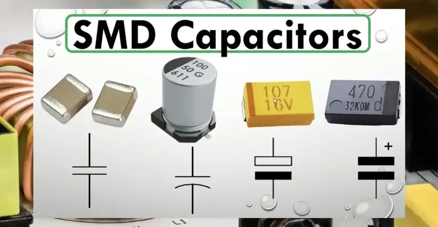
1000uF capacitors are commonly available in two primary package types: radial and surface mount (SMD). The selection between these depends largely on the application, physical constraints, and assembly methods. Radial capacitors feature leads that extend from the body, designed for through-hole mounting on a printed circuit board (PCB). In contrast, SMD capacitors are designed to be directly mounted on the surface of a PCB, without the need for through-holes. Each type has distinct characteristics that influence its suitability for different scenarios.
| Feature | Radial Capacitor | SMD Capacitor |
|---|---|---|
| Mounting Method | Through-hole | Surface Mount |
| Lead/Terminal Type | Leads extending from the body | Flat terminals on the body |
| Size and Form Factor | Typically larger, cylindrical shape | Typically smaller, rectangular or cylindrical shape |
| PCB Space Requirement | Requires more PCB space due to leads and mounting method | Requires less PCB space; more compact design |
| Assembly Process | Manual or automated through-hole assembly | Automated surface mount assembly (pick and place) |
| Thermal Performance | Leads aid heat dissipation | Directly connected to PCB, may require careful thermal management |
| Typical Applications | Prototyping, hand-assembled circuits, applications where space is not a major constraint | High-volume manufacturing, compact electronic devices, automated assembly |
| Cost | Generally less expensive | Generally more expensive due to automated processes |
Radial capacitors are often preferred for prototyping, hobbyist projects, and low-volume production due to their ease of manual placement and soldering. Their larger size and leaded design provide inherent advantages in heat dissipation. However, they occupy more board space. SMD capacitors, with their small size and suitability for automated assembly, are advantageous in high-volume manufacturing and compact devices. They offer a more efficient use of board space. When selecting a package type, consider the constraints and requirements of the application, balancing size, cost, ease of assembly, and thermal considerations.
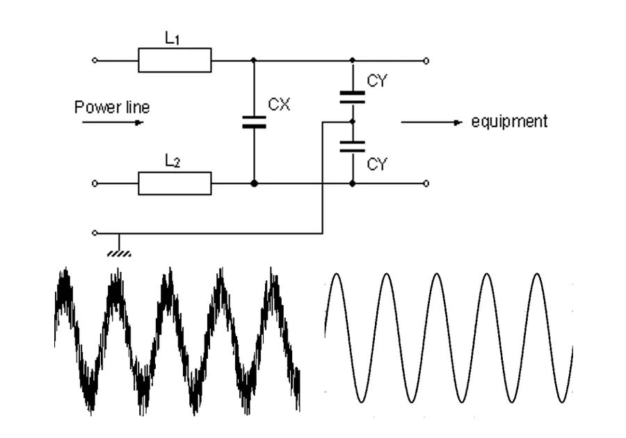
1000uF capacitors are crucial components in power supply circuits, acting as filters to eliminate unwanted AC ripple and noise from the DC output. This filtering action ensures a clean and stable voltage supply, essential for the proper functioning of sensitive electronic devices. They primarily perform a smoothing function, reducing voltage variations and providing a consistent power source.
The effectiveness of a 1000uF capacitor in power supply filtering is largely due to its relatively high capacitance. This allows it to store a significant amount of charge, which is then released to maintain a constant voltage during brief dips in power delivery. This is particularly important in switching power supplies, where the output voltage is not inherently smooth and requires substantial filtering.
| Application | Filter Type | Capacitor Role | Impact |
|---|---|---|---|
| Linear Power Supplies | Smoothing | Reduces output voltage ripple | Provides stable DC output |
| Switching Power Supplies | Output Filtering | Filters high-frequency switching noise | Ensures clean DC for devices |
| DC-DC Converters | Output Smoothing | Stabilizes converted voltage | Improves power efficiency |
| Audio Amplifiers | Power rail decoupling | Reduces noise on power rails | Enhances audio signal quality |
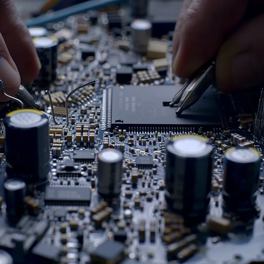
Replacing a 1000uF capacitor requires careful attention to detail and safety to ensure proper function of the repaired device and avoid personal harm. This section provides a step-by-step guide for safely removing a faulty capacitor and installing a new one.
Before beginning, it's critical to understand that capacitors can store a charge, even when the device is powered off. Therefore, the first step is always to discharge the capacitor safely.
This section addresses common queries about 1000uF capacitors, providing clear and concise answers to enhance understanding of their function and usage.
1000uF capacitors, while generally reliable, can exhibit failure modes that impact circuit performance. Identifying and addressing these issues promptly is crucial for maintaining the functionality and longevity of electronic devices. Common problems include failures leading to open circuits, reduced capacitance, or increased resistance, all affecting their intended purpose within a circuit.
The following table outlines common troubleshooting steps using testing methods to diagnose 1000uF capacitor issues:
| Symptom | Testing Method | Interpretation | Preventative Measure |
|---|---|---|---|
| Bulging or Leaking | Visual Inspection | Failed capacitor, needs replacement | Avoid overvoltage and high operating temperatures. |
| Open Circuit | Multimeter in resistance mode (Ω) | Infinite resistance indicates open circuit | Ensure proper operating conditions and periodic capacitor replacement as part of planned maintenance. |
| Reduced Capacitance | Capacitance meter | Significantly lower capacitance value than rated indicates degradation | Use high quality capacitors and avoid operating outside of their rated operating parameters. |
| Increased ESR | ESR meter | Higher ESR than specified by the datasheet indicates a failing capacitor. | Select capacitors rated for low ESR in high current applications. |
| Intermittent Operation | Thermal cycling and circuit testing | Erratic behavior due to temperature changes; confirms a failing component. | Replace with a high-temperature-rated capacitor. |
In summary, effective troubleshooting of 1000uF capacitors involves careful inspection, electrical testing, and implementation of preventative measures. Early detection of issues through periodic checks can significantly reduce downtime and prevent further damage to electronic circuits.
In summary, the 1000uF capacitor is a versatile and crucial component in many electronic circuits. From filtering noise in power supplies to acting as a temporary energy storage, the 1000uF capacitor's role cannot be overstated. By understanding its specifications, applications, and troubleshooting techniques, both hobbyists and professionals can better leverage the power of these tiny yet important components. Always double check the ratings of a 1000uF capacitor and be mindful of its proper application to ensure the best performance and long life for your project. Whether you're working on a simple circuit board or a complex electronic device, the knowledge about how a 1000uf capacitor operates is an invaluable asset.

