In the realm of electronics, the unassuming 100uF 16V capacitor plays a vital role in countless circuits, much like how a tiny gear powers a large clock. This seemingly simple component, often found in devices ranging from power supplies to audio circuits, stores electrical energy and influences signal behavior. This article will delve into the specifics of the 100uF 16V capacitor, explaining its function, key characteristics, and practical considerations, equipping you with a comprehensive understanding of this ubiquitous component.
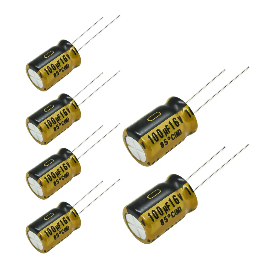
A 100uF 16V capacitor is a fundamental electronic component designed to store electrical energy temporarily. The '100uF' specifies its capacitance, which is the measure of its ability to store charge, while '16V' indicates its maximum operating voltage. Specifically, the 'uF' unit represents microfarads, where one farad (F) is a very large unit, and a microfarad is one millionth of a farad (10^-6 F). These capacitors, most commonly electrolytic, have a dielectric material that allows them to store a greater amount of charge in a small physical size.
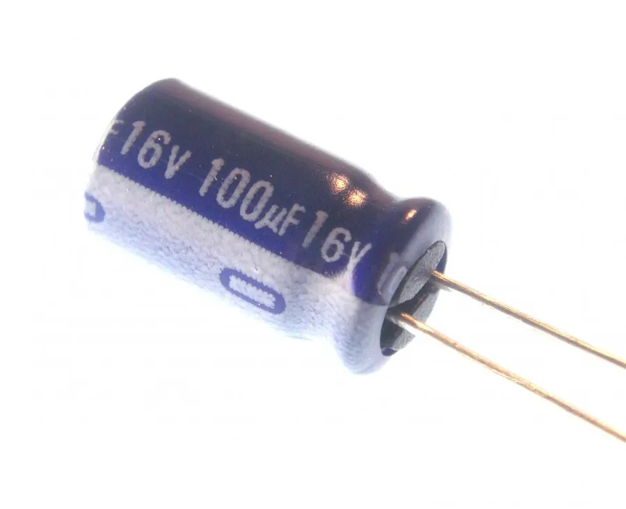
Beyond the fundamental capacitance (100uF) and voltage rating (16V), a 100uF 16V electrolytic capacitor is characterized by several crucial specifications that determine its suitability for a given application. These specifications include tolerance, operating temperature range, physical dimensions, Equivalent Series Resistance (ESR), and lifespan, which are all vital for engineers to consider.
| Specification | Description | Typical Values | Impact on Performance |
|---|---|---|---|
| Capacitance | Nominal value of charge storage capability. | 100uF (Microfarads) | Determines charge storage capacity and filtering effectiveness. |
| Voltage Rating | Maximum DC voltage the capacitor can handle safely. | 16V | Ensures reliable operation without risk of dielectric breakdown. |
| Tolerance | Permissible deviation from the nominal capacitance value. | ±20% or ±10% | Affects precision of timing and filtering circuits, tighter tolerance is preferred for critical applications. |
| Operating Temperature Range | Temperature range within which the capacitor operates reliably. | -40°C to +85°C or +105°C | Impacts reliability and lifespan, especially in high-temperature environments. |
| Dimensions | Physical size of the capacitor. | Varies widely: Radial (e.g., 5x11 mm), SMD (e.g., 6.3x5.4 mm) | Influences space utilization in circuit design; SMD options are smaller for compact designs. |
| ESR (Equivalent Series Resistance) | Internal resistance of the capacitor that causes energy loss. | Typically from 0.1 to 10 ohms depending on frequency and capacitor series | Higher ESR generates more heat and reduces capacitor efficiency. |
| Lifespan | Estimated duration of reliable performance of a capacitor in hours. | 2000 to 5000 hours (at rated temperature) | Impacts longevity of the circuit especially in harsh environments. |
These specifications are crucial for engineers to evaluate when designing electronic circuits, with tolerance impacting the precision of filtering, operating temperature affecting longevity, physical dimensions influencing board space, ESR contributing to energy loss and lifespan determining reliability.
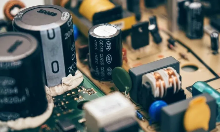
The 100uF 16V capacitor, primarily an electrolytic type, serves a multitude of crucial functions in electronic circuits. Its specific characteristics—100 microfarads of capacitance and a 16-volt rating—make it suitable for applications requiring moderate energy storage, voltage smoothing, and signal conditioning. These capacitors are indispensable for maintaining stable operating conditions and ensuring reliable performance in diverse electronic systems.
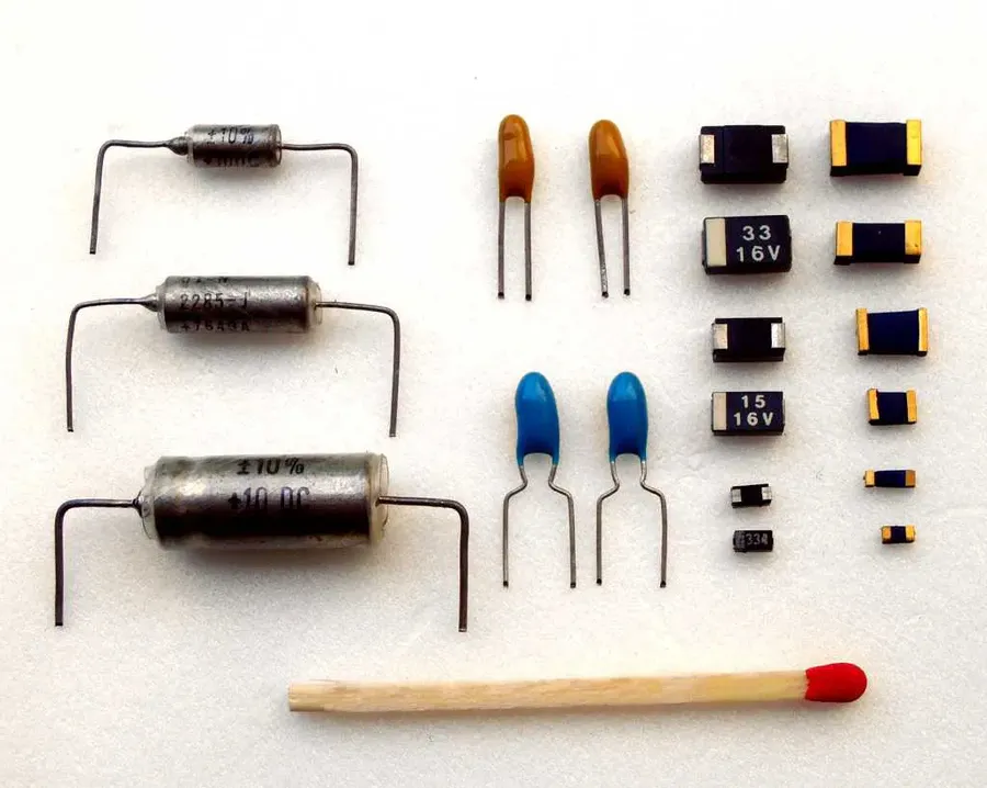
100uF 16V capacitors are commonly found in two primary mounting styles: radial leaded and surface mount device (SMD). Each type presents distinct advantages and disadvantages, making them suitable for different applications and assembly processes. The choice between radial and SMD formats is a crucial decision in electronic design, influencing both circuit performance and manufacturing efficiency.
| Feature | Radial Leaded Capacitor | SMD Capacitor |
|---|---|---|
| Mounting Style | Through-hole mounting, leads inserted into PCB holes. | Surface mounting, soldered directly to PCB pads. |
| Size | Typically larger, cylindrical shape with wire leads. | Smaller, rectangular or cylindrical without leads. |
| Ease of Use | Easier for manual assembly, prototyping, and breadboarding. | Requires automated pick-and-place machines for efficient assembly. |
| PCB Assembly | Requires drilling holes in the PCB for mounting. | Does not require drilling; soldered onto surface pads. |
| Typical Applications | Prototyping, older devices, applications where manual assembly is common, less dense designs. | High-volume manufacturing, compact designs, modern electronic devices. |
| Cost | Typically slightly lower for individual components. | Cost effective at scale in mass production due to automated assembly. |
| Lead Length | Available with varying lead lengths for diverse circuit layouts. | Designed for minimal size and direct surface contact with PCB. |
Radial capacitors are characterized by their wire leads extending from the body, facilitating through-hole mounting. Their larger size and leads make them more suitable for manual assembly, prototyping, and repair. SMD capacitors, in contrast, are designed to be soldered directly onto the surface of the PCB. Their compact size and leadless construction make them the preferred choice for high-density, automated manufacturing processes. The selection between radial and SMD capacitors significantly impacts PCB design, assembly, and the overall product's size and manufacturing cost.
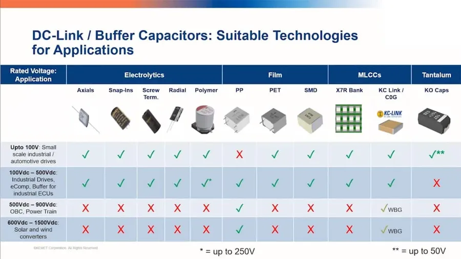
Choosing the correct 100uF 16V capacitor involves a meticulous evaluation of circuit requirements and operating conditions. It's not merely about matching the capacitance and voltage ratings; several other crucial factors influence long-term reliability and performance within the circuit. A misselected capacitor can lead to premature failure or unreliable functionality of the device.
| Factor | Description | Impact |
|---|---|---|
| Operating Voltage | The actual voltage that the capacitor will experience in the circuit. The capacitor's rated voltage (16V in this case) should be significantly higher than the maximum voltage it will encounter. | Ensures reliable operation without risk of dielectric breakdown and premature failure. |
| Temperature Range | The range of ambient temperatures in which the capacitor must operate. Commonly -40°C to +85°C, but some may be rated up to +105°C. | Affects capacitance, ESR, and lifespan. Operating outside the specified range can degrade performance. |
| Ripple Current | The amount of AC current that the capacitor is expected to handle without overheating. | Overheating can damage the capacitor and shorten its lifespan. |
| Physical Size and Form Factor | The dimensions of the capacitor and its mounting style (radial or SMD) including lead spacing and height. | Must match PCB layout and application requirements in order to physically fit. |
| ESR (Equivalent Series Resistance) | The resistance within the capacitor, which impacts heat dissipation and performance at higher frequencies. | Low ESR is critical for high-frequency applications like power filtering, minimizing power loss. |
| Tolerance | The permissible deviation of the actual capacitance from the specified value, usually expressed as a percentage. | Affects the precision of the circuit functionality. |
| Lifespan | Expected operational life of the capacitor, usually given in hours under specified conditions. | Critical for long-term reliability, particularly in applications with high operating temperatures. |
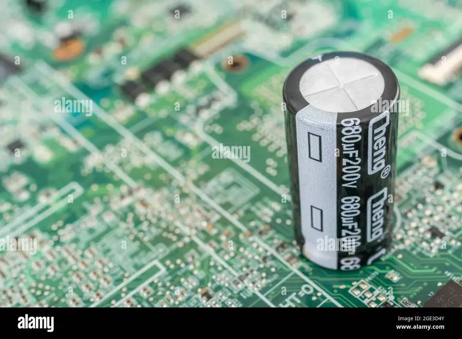
Capacitor markings provide critical information about the component's electrical characteristics and physical attributes. These markings, typically found on the capacitor's body, allow for proper identification and usage within a circuit. A 100uF 16V capacitor will have specific markings to identify its capacitance, voltage rating, polarity, and manufacturer.
| Marking Type | Description | Example on 100uF 16V Capacitor |
|---|---|---|
| Capacitance | Indicates the capacitor's ability to store charge, measured in Farads (F) or Microfarads (µF). | Typically marked as '100µF' or '100uF' |
| Voltage Rating | Specifies the maximum voltage the capacitor can safely withstand, indicated in Volts (V). | Marked as '16V' |
| Polarity | Indicates the correct connection orientation for polarized capacitors, such as electrolytics. Non-polarized capacitors usually lack polarity markings. | Marked with a stripe (usually white or grey) or a series of minus signs (-) closest to the negative terminal. |
| Manufacturer Logo | Indicates the company that manufactured the capacitor. | Various logos, unique to each manufacturer. |
| Temperature Range | Specifies the allowable temperature range for safe operation. | May be encoded (e.g., a number/letter code) or written explicitly, e.g., '85°C' or '105°C' |
| Tolerance | Indicates the allowed variation in the capacitance value, typically expressed as a percentage. | Marked with a letter code such as 'M' for ±20% or 'K' for ±10% |
| Series/Type Code | Often an alpha-numeric code used by the manufacturer to specify a particular capacitor series. | Varies by manufacturer, typically a combination of letters and numbers. |
Capacitor datasheets are essential documents provided by manufacturers, offering detailed specifications and performance characteristics crucial for selecting and implementing components correctly. For a 100uF 16V capacitor, the datasheet extends beyond the basic capacitance and voltage ratings, providing insights into a component's suitability for a specific application.
Understanding these datasheets ensures you make informed decisions, optimizing the circuit's performance and longevity. They typically include parameters such as dimensions, tolerance, temperature rating, equivalent series resistance (ESR), and lifespan.
Here's how to interpret key information from a typical 100uF 16V capacitor datasheet:
Reliable sources for datasheets include manufacturer websites (e.g., Panasonic, Murata, Vishay, Nichicon, TDK), and component distributors such as Mouser, Digi-Key, and Arrow. Always refer to the original datasheet from the manufacturer to ensure accuracy and avoid using datasheets that are not the latest version.
When consulting datasheets, it's crucial to verify that the part number precisely matches your needs. Be attentive to the specific characteristics required for your application to avoid mismatches and subsequent component failures. Understanding these details from the datasheet can make a difference in designing a robust, reliable, and efficient circuit.
This section addresses common queries regarding 100uF 16V capacitors, offering practical insights into their functionality and application. Understanding these FAQs will help in making informed decisions when using or replacing these components in electronic circuits.
The 100uF 16V capacitor is a cornerstone of modern electronics, quietly performing crucial tasks in a wide variety of circuits. Whether you're designing a complex digital system or just tinkering on a hobby project, a deep understanding of its specifications, selection criteria, and practical applications is essential. From their role in power supply filtering, decoupling noise in circuits or simply storing energy, these components enable the functionality we take for granted in our devices. Armed with this knowledge, you are now better equipped to integrate 100uF 16V capacitors into your projects with confidence and achieve optimal performance while knowing their limitations.

