In the intricate world of electronics, the 104 ceramic capacitor is a ubiquitous component. Like a tiny energy reservoir, this small but vital part plays a crucial role in countless devices. From smoothing power supply voltages to shaping circuit behavior, the 104 ceramic capacitor, with its 0.1uF capacitance, is an essential piece of the electronic puzzle. This article will delve deep into the world of this component, covering its specifications, applications, and practical considerations for anyone working with electronics. Let's unpack the secrets of the 104 ceramic capacitor and see why this component is so popular.
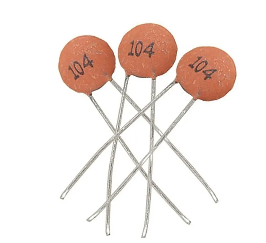
The '104' marking on a ceramic capacitor is a standardized code indicating its capacitance value. This code, not arbitrary, is essential for selecting the correct capacitor for electronic circuit design. It specifies a capacitance of 100,000 picofarads (pF), which translates to 0.1 microfarads (µF) or 100 nanofarads (nF), thus a 104 ceramic capacitor is rated at 0.1 microfarads.
| Unit | Value |
|---|---|
| Picofarads (pF) | 100,000 pF |
| Microfarads (µF) | 0.1 µF |
| Nanofarads (nF) | 100 nF |
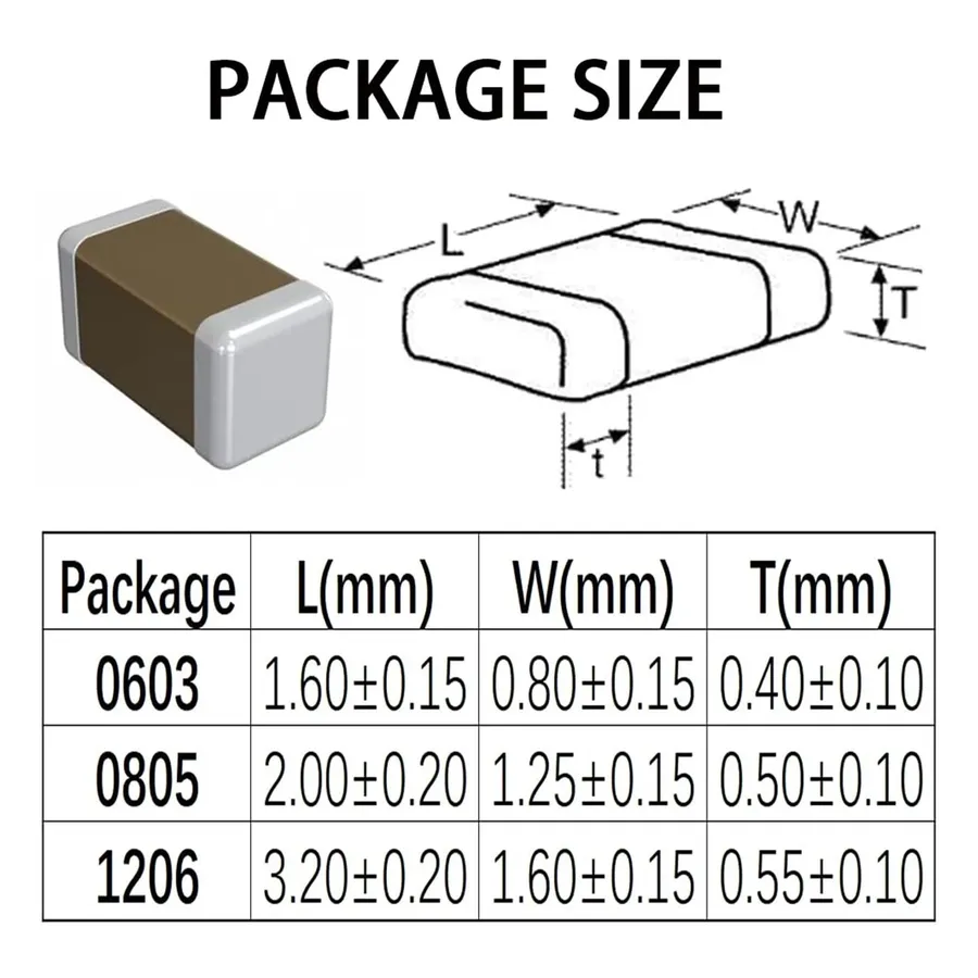
Beyond its capacitance value, a 104 ceramic capacitor is characterized by several critical specifications that directly influence its performance in electronic circuits. These specifications include voltage rating, tolerance, temperature coefficient, and dielectric material properties. Understanding these parameters is crucial for selecting the appropriate capacitor for a given application, ensuring circuit reliability and longevity.
| Specification | Typical Value | Description | Impact on Performance |
|---|---|---|---|
| Capacitance | 0.1 µF (100 nF) | The stored charge per unit voltage. | Determines the capacitor's ability to store electrical energy. |
| Voltage Rating | 50V (common, varies) | The maximum DC voltage that can be safely applied without risking dielectric breakdown. | Exceeding the rated voltage can lead to capacitor failure. |
| Tolerance | -20%/+80% (common) | The allowable deviation from the nominal capacitance value. | Affects the precision of timing and filtering circuits. |
| Temperature Coefficient | Varies by dielectric type (e.g., X7R, C0G) | The change in capacitance per unit change in temperature. | Determines the capacitance stability across varying temperatures. |
| Dielectric Material | Various (e.g., X7R, Y5V, C0G) | The insulating material between the capacitor's electrodes. | Influences temperature stability, voltage dependence, and aging. |
| Case Size | Varies (e.g., 0603, 0805) | The physical dimensions of the capacitor. | Affects the capacitor's mounting and compatibility with circuit board layout. |
It is imperative to note that the voltage rating is a critical parameter. Applying a voltage exceeding the capacitor's rating can cause dielectric breakdown, leading to short circuits or permanent damage. Furthermore, a wide tolerance range indicates that the actual capacitance value may vary significantly from the nominal 0.1uF, which can affect circuit performance, especially in precision applications. Temperature coefficient and dielectric material choice also play a vital role, impacting the stability and reliability of the capacitor under diverse operating conditions. Therefore, designers must carefully consider these specifications when selecting a 104 ceramic capacitor.
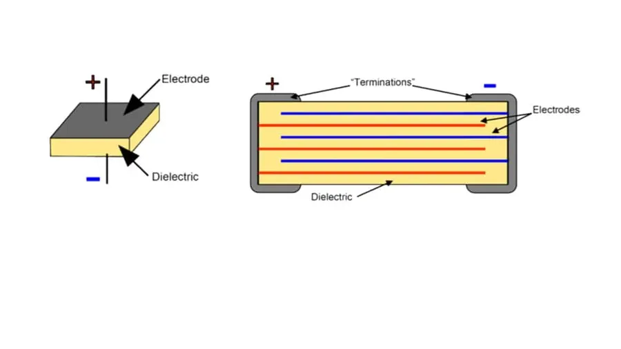
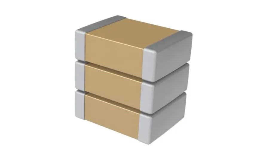
While the term 'monolithic capacitor' can sometimes encompass ceramic capacitors, it generally refers to multilayer ceramic capacitors (MLCCs) that are constructed with a specific internal structure. A 104 ceramic capacitor is usually a type of MLCC. This section focuses on differentiating the construction, applications and advantages of various monolithic capacitors including the 104.
| Feature | 104 Ceramic Capacitor (MLCC) | Other Monolithic Capacitors |
|---|---|---|
| Construction | Multiple layers of ceramic dielectric interleaved with metal electrodes, often with a barium titanate dielectric, resulting in a small size. | Similar layered construction with different dielectric materials such as polymers, tantalum or other ceramics, often resulting in different electrical and physical properties. |
| Capacitance Range | Typically in the range of picofarads to a few microfarads, with the 104 (100nF or 0.1uF) being a common value. | Wider range from picofarads to hundreds of microfarads, depending on the dielectric and size. |
| Voltage Rating | Commonly available in ratings from a few volts to several kilovolts, with 50V being a typical value for the 104. | Varies widely, from a few volts for tantalum and polymer capacitors, to kilovolts for high-voltage ceramic capacitors. |
| Temperature Stability | Can vary, with some formulations exhibiting significant changes in capacitance over temperature. COG/NPO formulations offer very high stability. | Varies based on the dielectric. Tantalum and polymer capacitors have lower temperature coefficients than many ceramic types but often lower capacitance density. |
| ESR(Equivalent Series Resistance) | Generally low, especially for smaller sizes, which is beneficial for high-frequency applications. | Can vary widely, polymer and tantalum have low ESR, while ceramic capacitors may have slightly higher ESR. This needs to be considered in high-current applications. |
| Typical Applications | Decoupling, bypass, filtering, and timing circuits, where size is a major consideration. | Bulk capacitance, power rail decoupling, and applications with high current demands, depending on the type. |
| Advantages | Small size, low cost, good high-frequency performance, and readily available. | Wider capacitance range, better stability or higher voltage capabilities in some cases. |
| Disadvantages | Can be susceptible to mechanical stress and can sometimes be microphonic. Limited capacitance compared to other monolithic types. | Higher cost in many cases, lower frequency performance or larger size depending on the dielectric type. |
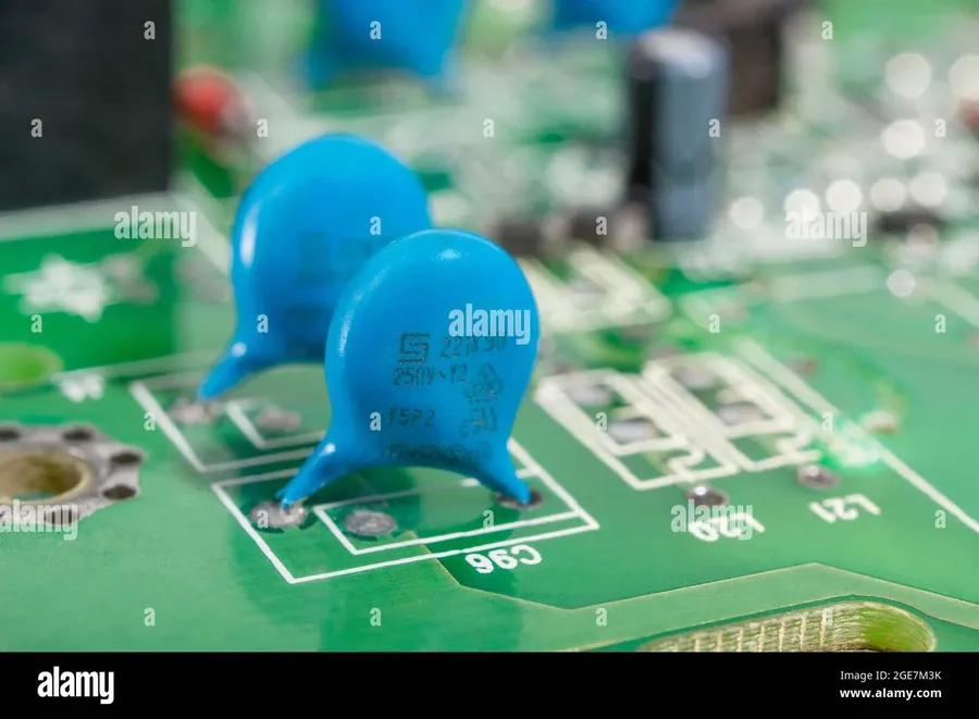
The 104 ceramic capacitor, with its 0.1µF capacitance, finds widespread use across diverse electronic applications. Its combination of a useful capacitance value, compact size, and relative low cost makes it a staple in many circuits. This section explores typical applications as well as some of its less common uses.
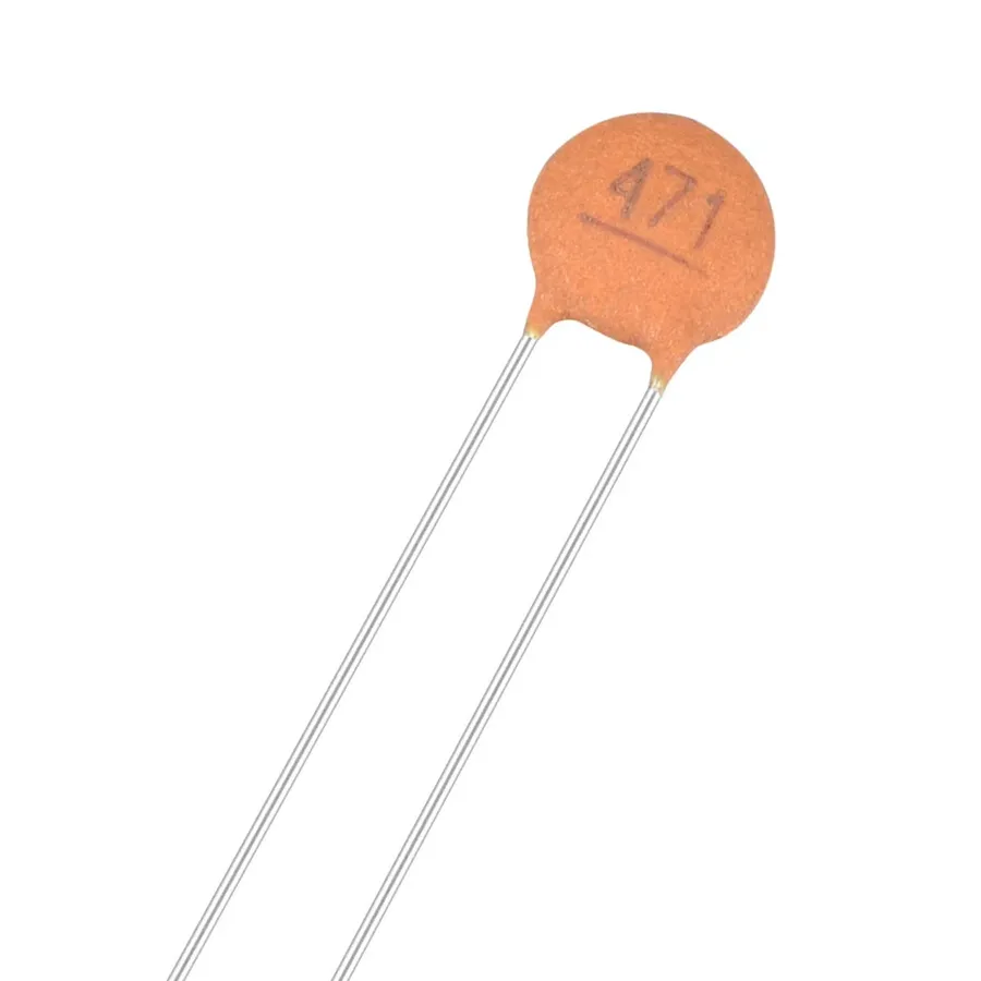
While 104 ceramic capacitors are generally robust, proper handling and usage are crucial for optimal performance and longevity. This section outlines essential practical considerations, including polarity awareness, mounting techniques, and soldering practices to ensure these components function reliably in your circuits.
104 ceramic capacitors are non-polarized components, meaning they can be installed in a circuit in either direction. However, while polarity isn't a concern for typical applications, it's important to note that specific circuit designs might require careful consideration of parasitic effects based on the capacitor's orientation. For example, if a design is very sensitive to noise or electromagnetic interference, the orientation of the capacitor with respect to nearby components may affect performance.
Mounting and soldering techniques are critical to ensure the integrity of the 104 ceramic capacitor. For surface mount components, using the correct solder paste and reflow profiles are essential to avoid cracking. For through-hole components, avoid excessive bending of leads, and ensure a good solder joint is created without overheating. These precautions prevent mechanical stress that can lead to internal damage or premature failure.
Proper soldering techniques are also crucial. Applying excessive heat or duration during soldering can lead to thermal shock, which may cause the capacitor's ceramic material to crack or change its electrical characteristics. The following best practices should be observed: Use a temperature-controlled soldering iron at the recommended temperature for your specific solder type. Avoid applying excessive pressure on the component and use enough solder to form a robust joint, but not so much that it over-fills the pad. Solder each capacitor within the maximum specified dwell time.
Identifying a faulty 104 ceramic capacitor is crucial for circuit reliability. This section details the methods for testing these capacitors, primarily using a multimeter, to assess their capacitance and detect common failures like shorts or open circuits.
A 104 ceramic capacitor, with its nominal capacitance of 0.1uF, can degrade over time or fail due to various stresses. Proper testing ensures the capacitor functions as intended within the circuit.
| Test | Expected Result for a Functional 104 Capacitor | Indication of a Faulty Capacitor |
|---|---|---|
| Visual Inspection | No visible damage | Cracks, chips, discoloration |
| Capacitance Measurement | Approximately 0.1uF (100nF), within tolerance | Significant deviation from 0.1uF, outside of the tolerance range (typically -20% to +80%) |
| Short Circuit Test | High resistance (no continuity) | Very low resistance (near zero ohms) or continuity |
| Open Circuit Test | Non-Zero capacitance measurement | Zero capacitance measurement |
This section addresses common inquiries regarding 104 ceramic capacitors, providing clarity on their specifications, usage, and comparison with similar components. Understanding these aspects is crucial for effective application in various electronic circuits.
Sourcing genuine 104 ceramic capacitors is crucial for reliable circuit performance. Counterfeit components can lead to unpredictable behavior and even system failures. This section provides guidance on identifying reputable sources to ensure you obtain authentic parts.
The 104 ceramic capacitor, with its 0.1uF capacitance, might be a tiny component, but it is crucial in the world of electronics. Its widespread use, versatility, and availability make it indispensable for countless applications. By understanding its specifications, applications, and best practices, you can harness the full potential of the 104 ceramic capacitor, driving your electronic projects with precision and reliability, and building better devices in your lab, your home or anywhere else electronics are needed. Keeping this in mind will help you effectively use the 104 ceramic capacitor.

