In the world of electronics, the transistor BC547 is like the workhorse that quietly powers countless devices. This NPN bipolar junction transistor is widely used for switching and amplification. From simple school projects to sophisticated industrial designs, understanding the BC547 is essential. In this article, we will dive deep into what the BC547 is, its key features, how it works, and practical ways you can use it.
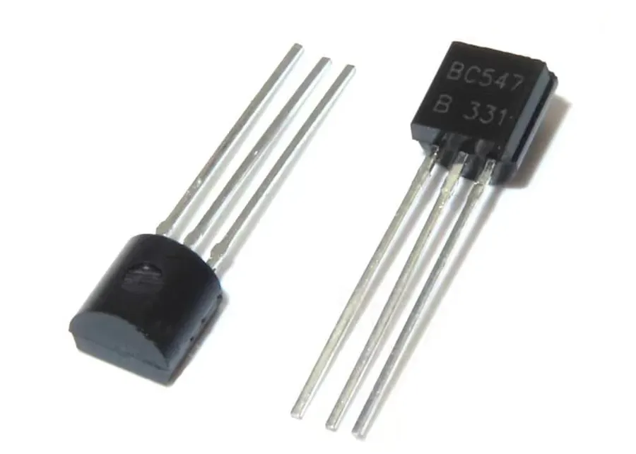
The BC547 is a ubiquitous NPN Bipolar Junction Transistor (BJT) widely employed in electronic circuits as a switch or amplifier. Understanding its fundamental structure and pin configuration is paramount for effective utilization. The BC547, like all BJTs, features three terminals: the Collector (C), the Base (B), and the Emitter (E), each playing a distinct role in its operation.
The BC547, when viewed from the front (flat side facing you, pins pointing down), has its pins arranged from left to right as follows: Emitter (E), Base (B), and Collector (C). This physical arrangement is crucial for proper circuit integration and avoids misconnections, which can lead to circuit malfunctions or damage to the transistor.
| Pin | Function | Description |
|---|---|---|
| Emitter (E) | Current Output | The terminal from which the current leaves the transistor. Usually connected to ground or a reference potential. |
| Base (B) | Control Input | The terminal used to control the current flow between the collector and emitter. A small current at the Base can control a larger current through the transistor. |
| Collector (C) | Current Input | The terminal where current enters the transistor. Usually connected to the load or power supply. |
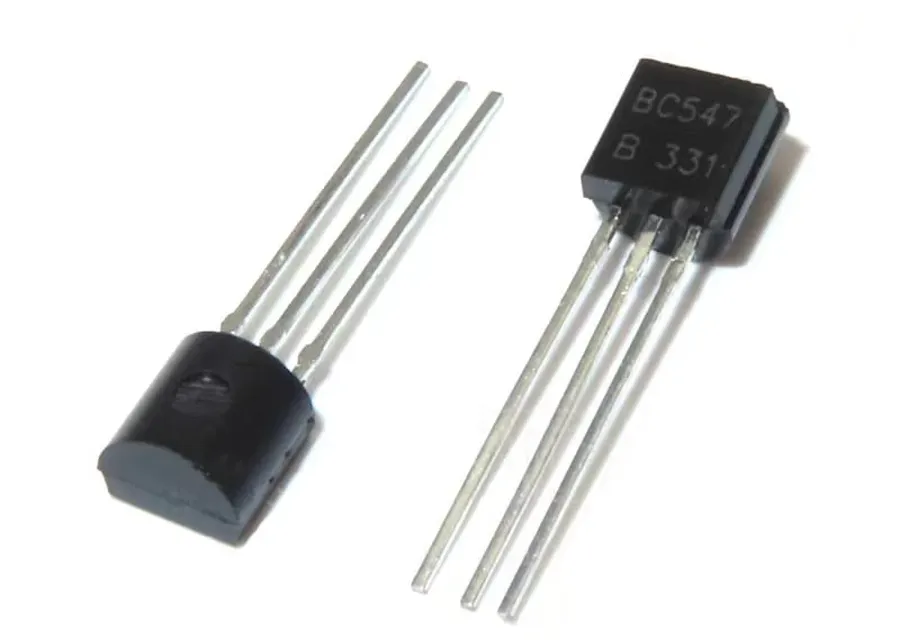
The BC547 is an NPN Bipolar Junction Transistor (BJT) characterized by several critical electrical parameters that dictate its performance in various applications. Understanding these specifications is crucial for proper circuit design and operation. Key parameters include the maximum ratings, which should never be exceeded to avoid damage, and typical operating characteristics that define the transistor's behavior under normal conditions.
| Parameter | Symbol | Value | Unit | Description |
|---|---|---|---|---|
| Collector-Emitter Voltage | VCEO | 45 | V | Maximum voltage allowed between collector and emitter. |
| Collector-Base Voltage | VCBO | 50 | V | Maximum voltage allowed between collector and base. |
| Emitter-Base Voltage | VEBO | 6 | V | Maximum voltage allowed between emitter and base. |
| Collector Current | IC | 100 | mA | Maximum continuous current that can flow through the collector. |
| Peak Collector Current | ICM | 200 | mA | Maximum peak current that can flow through the collector. |
| Total Device Dissipation | PD | 625 | mW | Maximum power the transistor can dissipate without damage. |
| DC Current Gain | hFE | 110-800 | - | Ratio of collector current to base current, varies by variant (A, B, C) |
| Transition Frequency | fT | 300 | MHz | Frequency at which current gain drops to unity. |
| Operating and Storage Temperature | Tj, Tstg | -65 to +150 | °C | Range of operating and storage temperatures |
The DC Current Gain (hFE), also known as beta (β), is a crucial parameter that determines the transistor's amplification capability. For the BC547, the hFE range is typically between 110 and 800. It's important to note the variations of this value for different suffixes (A, B, C) of the transistor, as this will affect circuit performance.
These specifications, especially the maximum collector current and power dissipation, must be carefully considered when designing circuits to ensure the BC547 operates within its safe limits, preventing any risk of thermal damage and ensuring the longevity and reliability of the circuit.
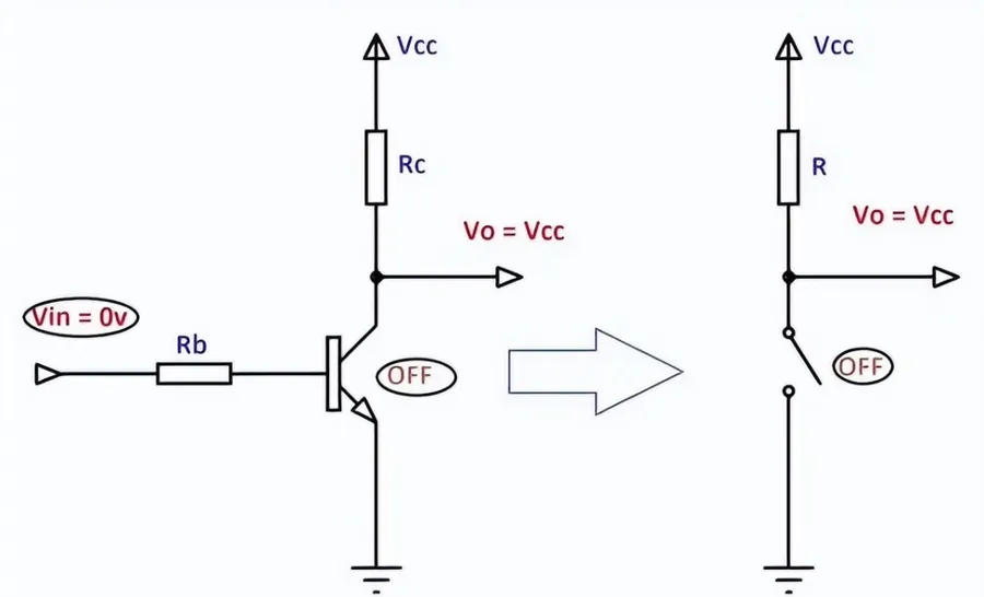
The BC547 transistor is frequently employed as an electronic switch, leveraging its ability to control a larger current flow with a smaller input current. This functionality is fundamental to numerous digital and control circuits, where the BC547 effectively acts as a gate, enabling or disabling the flow of current based on the signal applied to its base.
At its core, the BC547 operates as a switch by transitioning between two states: 'on' (saturation) and 'off' (cutoff). When a sufficient current is applied to the base pin, the transistor goes into saturation, allowing current to flow freely from the collector to the emitter. Conversely, when no current is applied to the base, the transistor enters cutoff, blocking current flow. This binary operation makes it suitable for various applications where on/off control is required.
| Parameter | Description | Implication |
|---|---|---|
| Base Current (Ib) | The current flowing into the Base pin. Typically a few mA or less. | Controls the state of the transistor switch. Sufficient Ib will turn the switch ON. |
| Collector-Emitter Current (Ic) | The current flowing from the Collector to Emitter when the transistor is ON. | The amount of current the BC547 can handle when saturated. This is often significantly larger than Ib. |
| Saturation Voltage | The voltage drop across the Collector and Emitter when the transistor is fully ON. | Typically quite low and close to 0V. Minimizing power loss. |
| Cutoff Current | The current flowing between the collector and emitter when the transistor is OFF. | Very low. Ideally zero, but a small leakage current may be present. |
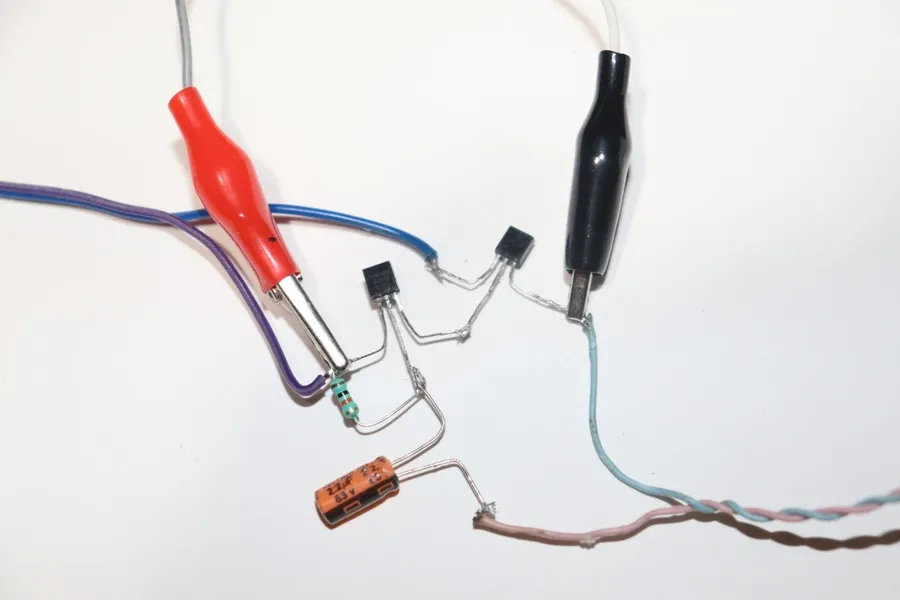
The BC547 transistor's capacity to amplify weak electrical signals is a cornerstone of its widespread use in electronics. By carefully configuring the transistor within a circuit, it can significantly increase the power of an input signal, a function crucial in diverse applications from audio processing to sensor signal conditioning. The common-emitter configuration is a particularly effective method to achieve this amplification.
The common-emitter amplifier leverages the BC547's inherent current gain (hFE). In this setup, the input signal is applied to the base of the transistor, while the output signal is taken from the collector. A small change in base current leads to a proportionally larger change in collector current, thus achieving amplification. The gain of this configuration can be substantial, allowing weak input signals to be boosted to usable levels.
The precise amount of amplification is determined by external circuit components such as resistors and capacitors, allowing for fine-tuning to meet specific requirements. However, the use of BC547 in amplification also introduces certain challenges, such as noise and distortion, which must be addressed in circuit design. Understanding these challenges ensures that the transistor operates within optimal parameters, minimizing unwanted artifacts in the amplified output signal. The BC547 is not typically used for high power amplification.
| Parameter | Typical Value (Common-Emitter) | Impact |
|---|---|---|
| Voltage Gain | High (adjustable with resistors) | Boosts the signal voltage. |
| Current Gain | Approximately equal to hFE | Increases the signal current. |
| Power Gain | Product of current and voltage gains | Overall amplification of the signal. |
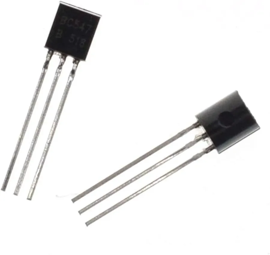
The BC547 transistor family includes several variants, primarily differentiated by their DC current gain (hFE) ranges. While all are NPN bipolar junction transistors, the subtle variations in hFE make a significant difference in circuit design, particularly in amplification and switching applications. Understanding these variations is crucial for achieving the desired circuit performance.
| Transistor Variant | hFE (DC Current Gain) Range | Typical Applications |
|---|---|---|
| BC547 | 110 - 800 | General-purpose amplification and switching |
| BC547A | 110 - 220 | Circuits requiring lower gain or more predictable amplification |
| BC547B | 200 - 450 | Common amplification circuits, medium gain |
| BC547C | 400 - 800 | Circuits needing higher gain, high-sensitivity applications |
The selection of a BC547 variant (A, B, or C) should be guided by the specific gain requirements of your circuit. For instance, a low-gain amplifier might benefit from the BC547A, while a high-sensitivity sensor amplifier would be better suited for the BC547C. It's also critical to consult the datasheet for precise hFE values, as these ranges represent typical values.
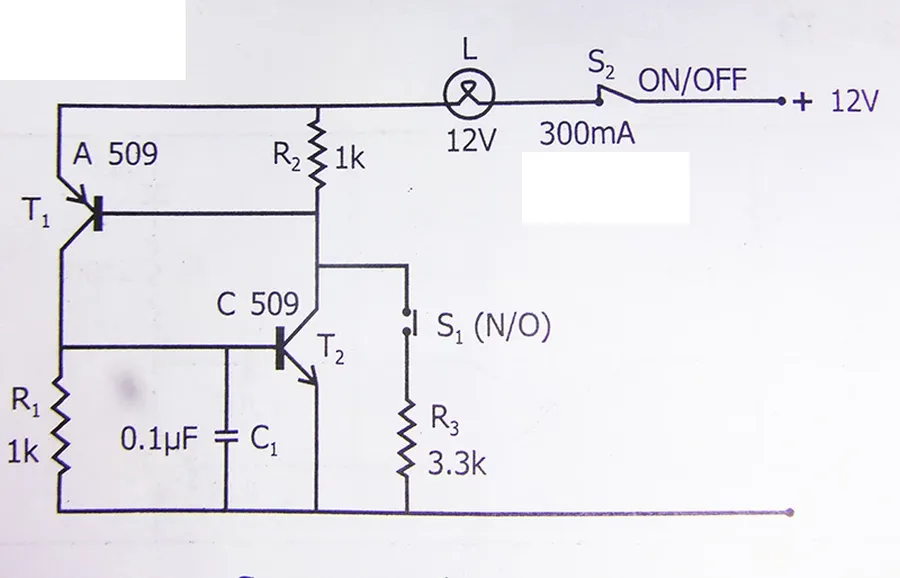
When the BC547 transistor is unavailable or unsuitable for a specific application, several alternatives can be used. Understanding the characteristics of these substitutes is crucial for seamless circuit design and troubleshooting. This section details commonly used alternatives, emphasizing their similarities and differences to the BC547, and provides guidelines for ensuring a proper substitution.
| Parameter | BC547 | BC550 | 2N3904 | 2N2222 |
|---|---|---|---|---|
| Type | NPN | NPN | NPN | NPN |
| Collector-Emitter Voltage (VCEO) | 45V | 45V | 40V | 40V |
| Collector Current (IC) | 100mA | 100mA | 200mA | 800mA |
| DC Current Gain (hFE) | 110-800 | 110-800 | 100-300 | 50-300 |
| Transition Frequency (fT) | 300 MHz | 300 MHz | 300 MHz | 250 MHz |
| Package | TO-92 | TO-92 | TO-92 | TO-18 or TO-92 |
The BC550 is a very similar NPN transistor with comparable characteristics to the BC547, making it a good general-purpose replacement. It features a similar voltage and current handling capability and comes in the same TO-92 package. The 2N3904 and 2N2222 are also NPN transistors frequently used in similar applications. The 2N3904 is widely available and is a suitable substitute with a slightly higher current rating (200mA) and similar fT while the 2N2222 has higher collector current(800mA) , lower DC current gain , lower fT. When replacing the BC547 with these alternatives, it is essential to verify the pin configuration, as different transistor pinouts may be required depending on the part. Always refer to the datasheets of the replacement transistors to confirm their specific parameters and circuit compatibility before final implementation.
Substituting the 2N3904 for the BC547 can be a viable option, but care must be taken to ensure proper circuit design to account for any differences in gain, and voltage drop.
This section addresses common queries regarding the BC547 transistor, providing concise and informative answers to help users understand its characteristics, applications, and alternatives.
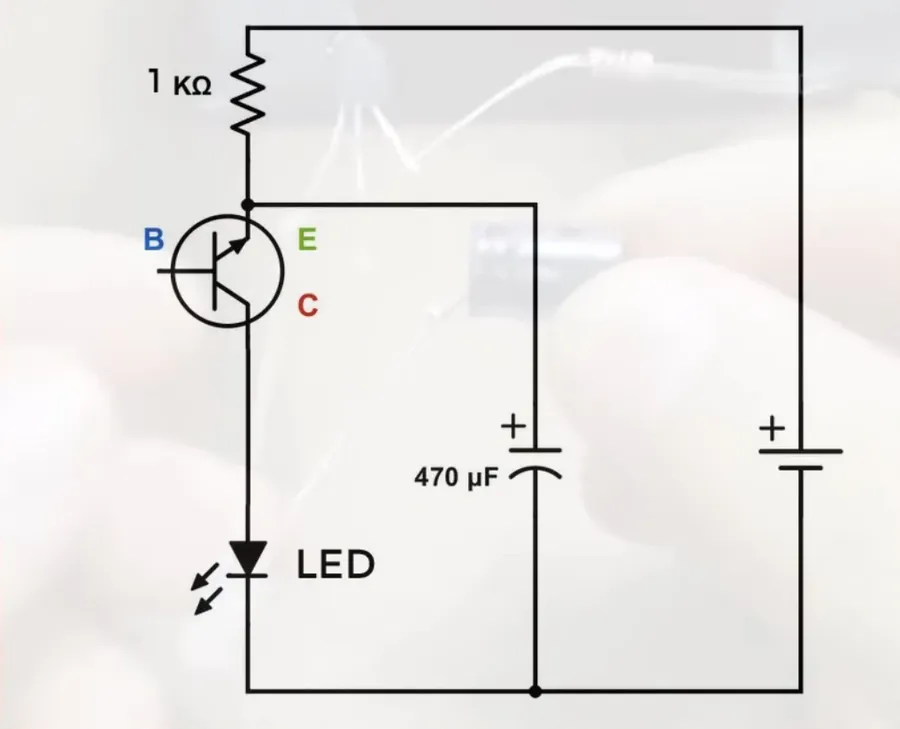
Successfully integrating a BC547 transistor into a circuit requires careful handling, thermal management, and correct soldering techniques. These practices ensure optimal performance and prevent premature failure, and include accurate pin identification before use.
Effective troubleshooting of BC547 transistor circuits requires a systematic approach, combining understanding of its characteristics with careful testing. Issues commonly arise from incorrect wiring, component failures, or misinterpretation of the transistor's behavior within a specific circuit. A methodical approach is crucial for isolating and resolving these problems, ensuring that the circuit operates as designed.
The transistor BC547, with its versatility and reliability, remains a cornerstone in electronic circuits, being an NPN BJT that's easy to use for both switching and amplification. Its widespread availability and low cost make it a popular choice for hobbyists and professionals alike. Understanding the principles behind BC547 functionality empowers us to create, innovate, and continue building the technological world around us. As technology evolves, the fundamental principles of components like the BC547 will continue to be essential knowledge for anyone interested in the field of electronics.

