Just as a water tower stores water for later use, capacitors in AC circuits are fundamental components that store and release electrical energy. This seemingly simple function has a profound impact, not just in power systems and sophisticated electronics, but also in everyday devices like the AC unit humming in your house. This article delves into the heart of how these electrical reservoirs operate within AC environments, aiming to provide a clear understanding of their crucial role.
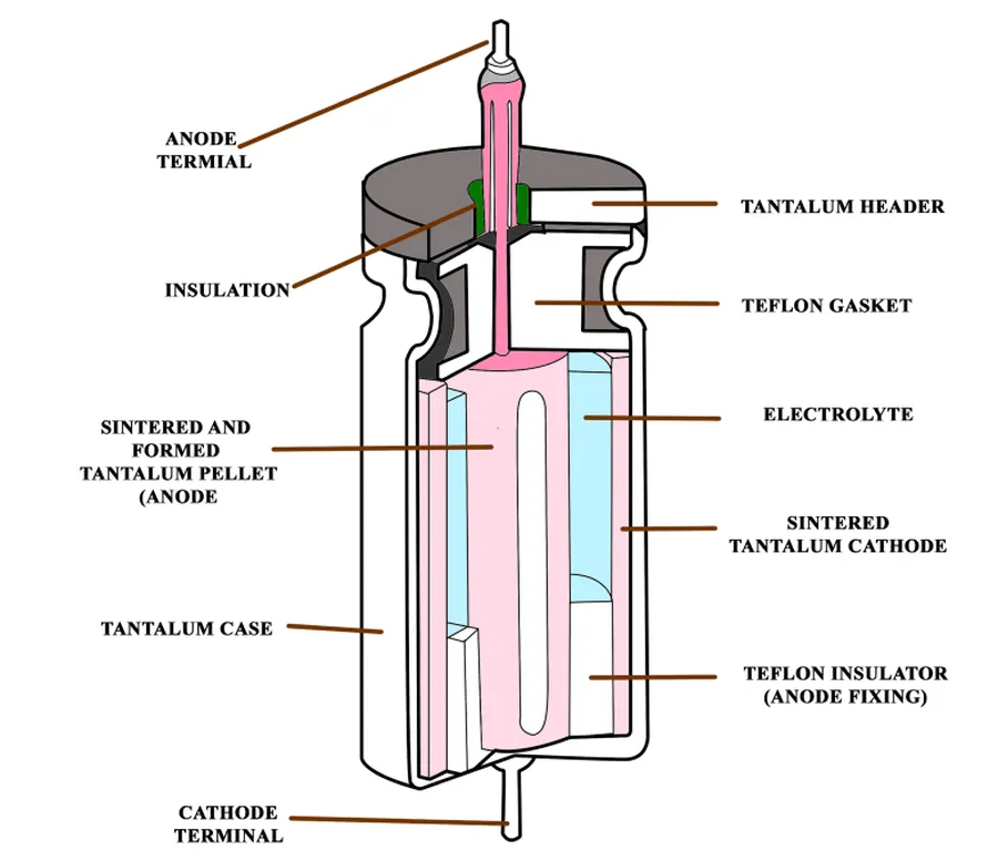
A capacitor, at its core, is an electrical component designed to store energy electrostatically within an electric field. This ability is achieved through its fundamental structure: two conductive plates, often made of metal, separated by a non-conductive material called a dielectric. This dielectric, which can be air, ceramic, film, or other insulators, prevents direct electrical contact between the plates while enabling the storage of electrical charge.
The operation of a capacitor hinges on the principle of charge accumulation. When a voltage is applied across the capacitor, an electric field is generated between the plates, causing electrons to accumulate on one plate (creating a negative charge) and deplete from the other (creating a positive charge). This separation of charge stores electrical potential energy. Unlike a battery, which stores energy chemically, a capacitor stores energy electrostatically, which enables it to rapidly charge and discharge, which is essential in AC circuits.
| Feature | Capacitor | Battery |
|---|---|---|
| Energy Storage Mechanism | Electrostatic | Chemical |
| Charge/Discharge Speed | Rapid | Relatively Slow |
| Voltage Characteristics | Voltage changes with charge | Relatively Constant Voltage |
| Primary function | Store energy, control voltage | Provide constant voltage and current |
Furthermore, the behaviour of capacitors in AC circuits differs from DC circuits. In DC circuits, once the capacitor is fully charged, it blocks the flow of current, acting as an open circuit. However, in AC circuits, where the voltage and current are constantly changing, the capacitor continuously charges and discharges, leading to unique behaviour such as capacitive reactance and phase shifts, which are critical in many applications.
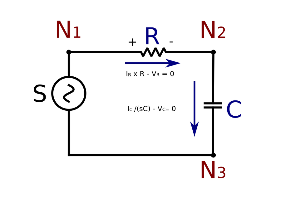
In alternating current (AC) circuits, capacitors exhibit a dynamic behavior characterized by continuous charging and discharging cycles. This behavior is fundamentally different from their role in direct current (DC) circuits, where they block current flow once fully charged. In AC, a capacitor's continuous interaction with the alternating voltage leads to a phenomenon known as capacitive reactance, which is the opposition to changes in voltage.
The dynamic response of a capacitor to AC voltage is due to the oscillating nature of the current. As the voltage across a capacitor increases, it stores charge; as the voltage decreases, it releases charge. This constant exchange results in a current flow that is phase-shifted relative to the voltage. Specifically, in a purely capacitive AC circuit, the current leads the voltage by 90 degrees.
The continuous charging and discharging behavior also contributes to the 'blocking' effect that capacitors have on DC and the ‘passing’ effect on AC signal. When voltage fluctuates in the circuit, the capacitor stores and releases energy to maintain a stable voltage level. This means that in a sinusoidal AC voltage circuit, the capacitor can be thought of as presenting a frequency-dependent impedance, unlike the frequency-independent resistance in a purely resistive circuit. This impedance, the capacitive reactance, impedes changes in voltage.
Capacitors do not 'pass' current in the sense of a wire. Rather, they facilitate current flow by repeatedly storing and releasing electrical energy, effectively allowing AC to 'pass' while blocking DC. This is fundamental to the capacitor’s role in filtering, signal coupling and energy storage applications.
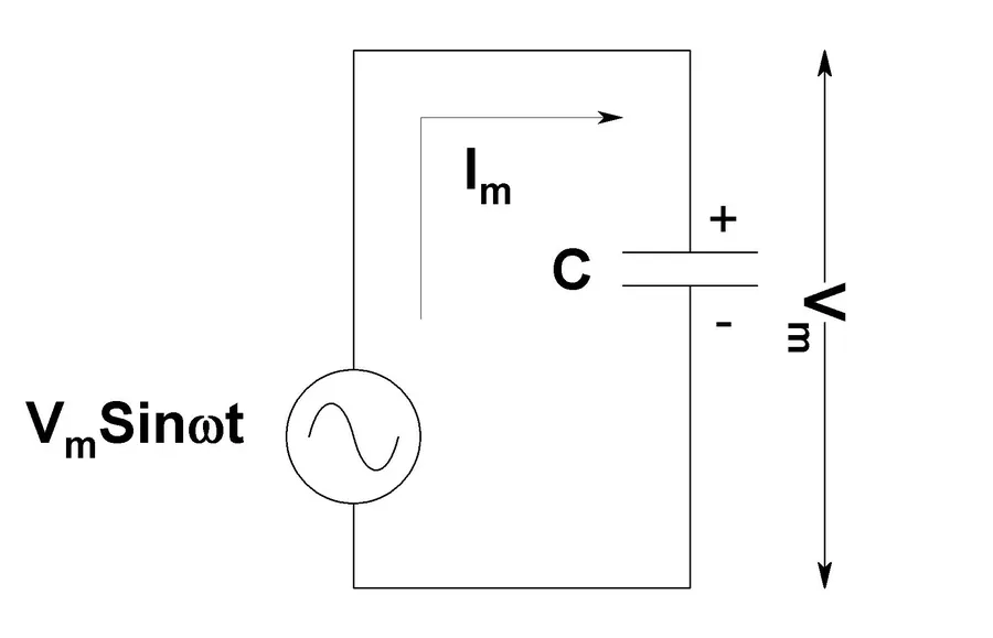
Capacitive reactance is the opposition a capacitor presents to alternating current (AC) flow, quantified in ohms, and unlike resistance, it is inversely proportional to the frequency of the AC signal. This frequency dependence is a key characteristic that differentiates capacitors from resistors in AC circuits, directly impacting how they behave in various applications.
Capacitive reactance (Xc) is calculated using the following formula:
X_c = \frac{1}{2\pi f C}
Where: - Xc is the capacitive reactance in ohms (Ω). - f is the frequency of the AC signal in hertz (Hz). - C is the capacitance in farads (F).
| Parameter | Description | Impact on Capacitive Reactance |
|---|---|---|
| Frequency (f) | The rate at which the AC signal oscillates. | Inversely proportional: higher frequency, lower Xc. |
| Capacitance (C) | The capacitor's ability to store electrical charge. | Inversely proportional: higher capacitance, lower Xc. |
| Temperature | Temperature will change the capacitance value, which in turn will affect the capacitive reactance. | Varies depending on the type of capacitor. Temperature is often a negligible factor. |
The key takeaway from this relationship is that capacitors act as 'frequency-dependent resistors' in AC circuits. At high frequencies, their reactance is low, allowing more current to flow, while at low frequencies, their reactance is high, impeding current flow.
This behavior is fundamentally different from resistors, which exhibit constant resistance regardless of frequency. Capacitive reactance is a crucial concept for designing and analyzing circuits that use AC signals, including filters, oscillators, and power supplies.
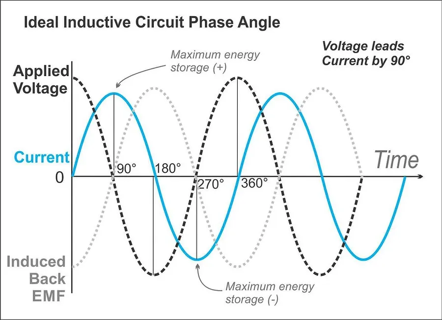
In alternating current (AC) circuits, capacitors introduce a crucial phase shift between the voltage and the current. This phenomenon is fundamental to understanding how capacitors behave in AC systems and is a key consideration in circuit design and analysis.
Specifically, in an AC circuit with a capacitor, the current leads the voltage by a phase angle of 90 degrees, or π/2 radians. This phase difference arises from the capacitor's inherent property to store charge and thus impede changes in voltage, resulting in a current that reaches its peak before the voltage does.
This 90-degree phase shift is a defining characteristic of capacitors in AC circuits. It has significant implications for power delivery, energy storage, and overall circuit performance. Unlike resistors, which have no phase difference between voltage and current, capacitors introduce this temporal offset, which must be carefully accounted for in AC circuit design.
The phase shift can be represented graphically using a phasor diagram. In this diagram, the current phasor is represented as leading the voltage phasor by 90 degrees in the counter-clockwise direction. The lengths of the phasors represent the magnitudes of the current and voltage, respectively, while their orientation indicates the phase angle with respect to each other.
The phase shift introduced by capacitors affects the power consumed in the circuit. Unlike in purely resistive circuits where power is continuously dissipated, in a capacitive circuit, energy is stored and returned to the source during different parts of the AC cycle. This leads to what's known as reactive power, which doesn’t do any actual work, but is essential to the system and impacts the overall efficiency of the system.
Understanding and utilizing this phase shift is essential for various applications, including power factor correction, filtering, and timing circuits. Proper management of phase relationships contributes to improved system stability, performance, and energy usage.
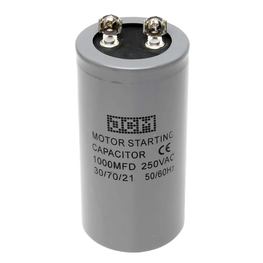
Capacitors are indispensable in AC power systems, especially within inductive loads such as motors found in air conditioning units and other appliances. Their primary functions include providing the initial surge of electrical energy needed for motor startup, storing energy to mitigate power fluctuations and assisting with power factor correction. These functions are critical for the reliable and efficient operation of many AC-powered devices.
Specifically, when an AC motor starts, it requires a high starting torque to overcome its inertia. This torque is directly related to the initial current flow which, in an inductive motor, is hampered by back electromotive force. A capacitor, placed in series with a starting winding, provides a phase shift to allow the initial current surge, providing the required torque to the motor. Once the motor reaches operational speed, the capacitor is often disconnected by a centrifugal switch, as it is no longer required for the continued running of the motor.
| Function | Description | Typical Applications |
|---|---|---|
| Motor Starting | Provides initial electrical boost required to start AC motors by introducing a phase shift. | Air conditioners, refrigerators, pumps |
| Energy Storage | Stores electrical energy during the AC cycle to support voltage stability, mitigates power fluctuations. | Power supplies, uninterruptible power supplies (UPS) |
| Power Factor Correction | Reduces reactive power in AC systems by adjusting the phase relationship between current and voltage. | Industrial machinery, large-scale electrical installations |
Power factor correction is a critical aspect where capacitors play a vital role. In AC systems with inductive loads, the current lags the voltage, leading to a poor power factor. Poor power factor results in higher energy consumption, increased utility costs, and reduced system efficiency. By introducing capacitors into the system, the reactive power demand is decreased, thus improving power factor. This correction leads to more efficient use of electrical energy and reduces the burden on the power grid.
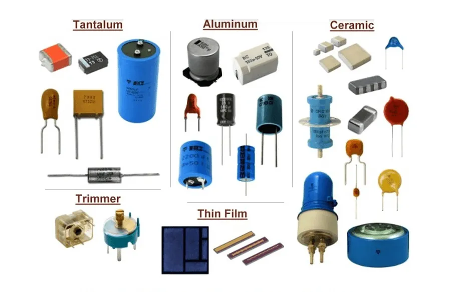
The selection of a capacitor for an AC application hinges on a multitude of factors, including voltage and current demands, financial constraints, physical size limitations, and the desired performance characteristics. Each capacitor type possesses unique attributes that make it suitable for specific applications within AC circuits.
| Capacitor Type | Dielectric Material | Typical Applications in AC | Key Characteristics | Advantages | Disadvantages |
|---|---|---|---|---|---|
| Electrolytic Capacitors | Aluminum Oxide or Tantalum Oxide | Power supplies, motor starting circuits | High capacitance, polarized | High energy storage in a small volume, relatively low cost | Limited frequency response, polarized (must be connected with correct polarity), shorter lifespan compared to other types, prone to drying out |
| Ceramic Capacitors | Ceramic compounds (e.g., barium titanate) | Bypass and coupling circuits, resonant circuits | Low cost, non-polarized, small size | Excellent high-frequency performance, low cost, good temperature stability | Lower capacitance compared to electrolytic and film capacitors, can be microphonic, capacitance can vary with voltage |
| Film Capacitors | Polyester, polypropylene, or other polymers | Power factor correction, motor run capacitors, high-frequency applications | Non-polarized, good stability, range of voltage and capacitance options | Good stability and tolerance, non-polar, long life, good high frequency performance | Larger size compared to ceramic capacitors, higher cost than ceramic capacitors |
| Paper Capacitors | Paper impregnated with oil or wax | Older equipment, high-voltage AC applications | High voltage tolerance, good reliability | High voltage applications, ability to self-heal | Large size, prone to aging and degradation, not commonly used in modern applications |
A faulty capacitor in an AC unit manifests through several telltale signs, predominantly stemming from its diminished ability to store and release electrical energy effectively. This section provides clear diagnostic methods, focusing on identifying the symptoms and outlining testing procedures while emphasizing necessary safety precautions to ensure safe handling.
Testing procedures for capacitors should be done by qualified personnel, using a multimeter capable of measuring capacitance. Ensure the power is completely disconnected before any testing or handling. Capacitors can retain a charge, posing an electrical shock hazard. Prior to testing, use a discharge tool to safely deplete any stored energy. Measurement results outside the nominal capacitance range (typically ±5% to ±10% of the rating printed on the capacitor) suggest the component needs replacing.
This section addresses common queries regarding capacitors in AC circuits, focusing on practical issues like failure symptoms, replacement costs, and operational necessities. Understanding these points is crucial for effective maintenance and troubleshooting of AC systems.
Diagnosing issues with AC capacitors typically involves recognizing symptoms, performing basic tests, and prioritizing safety. This section provides a practical guide for identifying common problems, understanding when to attempt a fix, and knowing when professional assistance is necessary. Proper troubleshooting helps prevent further damage and ensures safe, efficient operation of your AC system.
Capacitors in AC circuits, much like a power bank for your devices, are not just components; they are the silent workhorses driving many of the technologies we rely on daily. From ensuring the smooth operation of your air conditioner to optimizing power delivery in large-scale systems, their ability to store and release energy makes them indispensable. Understanding their behavior in AC circuits allows for better maintenance, design, and a greater appreciation for the electronics around us, showing that the world of electrical engineering is as fascinating as it is essential.

