Electrical circuits are the lifeblood of modern technology, forming the unseen pathways through which electricity flows, powering everything from our smartphones to our homes. This article will delve into the fundamental principles of electrical circuits, explaining their components, functions, and how they are used in daily life. By exploring the basic building blocks of circuits, we can gain a deeper understanding of how electricity works and the critical role it plays in our society.
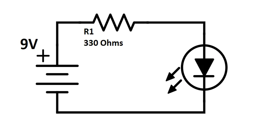
An electrical circuit is fundamentally a closed loop or pathway that facilitates the continuous movement of electric charge. This uninterrupted flow of charge carriers, typically electrons, constitutes an electric current. A complete and unbroken conductive path is essential for the establishment and maintenance of a current; without this closed loop, no current will flow, analogous to water flow requiring a closed pipe system.
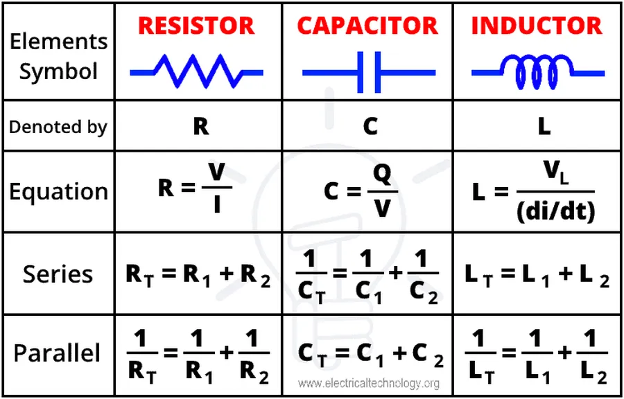
Electrical circuits are comprised of fundamental components, each with specific roles in enabling the flow of electrical current. These components work together to create a functional path for electrons, facilitating the operation of various electrical devices and systems.
| Component | Symbol | Function | Unit |
|---|---|---|---|
| Voltage Source (Battery/Power Supply) | Long and short parallel lines or a circle with + and - signs | Provides the electromotive force (voltage) to push electrons through the circuit. | Volts (V) |
| Conductor (Wire) | Straight line | Provides a path for current to flow with minimal resistance. | Ohms (Ω), typically very low |
| Resistor | Zigzag line or rectangle | Opposes the flow of current, dissipating electrical energy as heat. | Ohms (Ω) |
| Capacitor | Two parallel lines | Stores electrical energy in an electric field. | Farads (F) |
| Inductor | Coiled line | Stores energy in a magnetic field when current flows through it, opposing changes in current. | Henrys (H) |
| Switch | A break in the line with a movable contact | Controls the flow of current in the circuit by opening or closing the path. | N/A |
Understanding the symbols of circuit components is crucial for interpreting and creating circuit diagrams. Each component contributes to the behavior and functionality of the entire circuit, and the interaction between these components dictates how the circuit will operate.
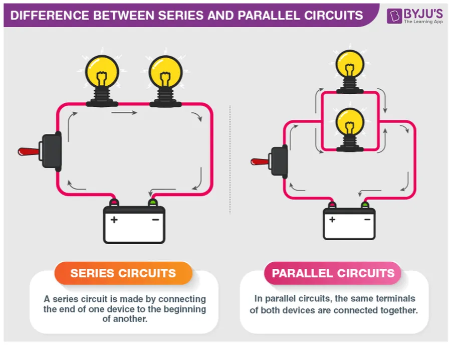
Electrical circuits are broadly categorized into three fundamental types: series circuits, parallel circuits, and combination circuits. Each type exhibits distinct behaviors in terms of current flow, voltage distribution, and overall circuit characteristics, making them suitable for different applications and design requirements.
| Characteristic | Series Circuit | Parallel Circuit | Combination Circuit |
|---|---|---|---|
| Current | Same through all components | Divides among branches | Varies depending on series and parallel sections |
| Voltage | Divides among components | Same across all branches | Varies depending on series and parallel sections |
| Resistance | Total resistance is the sum of individual resistances (Rtotal = R1+R2+...) | Total resistance is calculated using the reciprocal formula (1/Rtotal = 1/R1 + 1/R2 +...) | Calculated by combining series and parallel rules |
| Component Failure Impact | A break in any component results in complete circuit failure | Failure in one branch doesn't affect other branches | Impact depends on specific location |
| Wiring Complexity | Simple, single path | More complex, multiple paths | Variable, depends on series and parallel sections |
| Typical Applications | Simple light circuits, basic electronic devices | Household power distribution, complex electronic systems | Real-world complex devices and systems |
Ohm's Law is a fundamental principle in electrical circuit analysis, establishing a direct proportionality between voltage, current, and resistance within a circuit. This relationship is the cornerstone for understanding how electrical components interact and for predicting circuit behavior. Further analysis incorporates Kirchhoff’s Laws, expanding our ability to analyze complex circuits.
| Law/Concept | Description | Formula | Application |
|---|---|---|---|
| Ohm's Law | Relates voltage (V), current (I), and resistance (R) in a circuit. | V = IR | Calculating any one parameter when the other two are known. |
| Kirchhoff's Current Law (KCL) | The algebraic sum of currents entering a node (junction) is equal to the algebraic sum of currents leaving that node. | ∑I_in = ∑I_out | Analyzing current distribution at a circuit node. |
| Kirchhoff's Voltage Law (KVL) | The algebraic sum of voltages around any closed loop in a circuit is equal to zero. | ∑V = 0 | Analyzing voltage drops and sources in a closed loop. |
These laws are crucial for solving circuit problems. For example, using Ohm's Law, one can easily calculate the current flowing through a resistor given the voltage across it and its resistance, or calculate the voltage drop across the resistor given its resistance and the current flowing through it. Similarly, Kirchhoff’s Laws help analyze more complex circuits, allowing us to calculate currents and voltages at any given node or loop in a circuit.
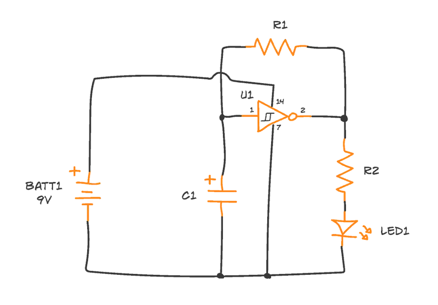
Circuit diagrams and schematics are essential visual languages used to represent electrical circuits. They provide a standardized way to communicate the structure and connections within a circuit, using symbols to represent components and lines to represent connections. Understanding these diagrams is crucial for designing, analyzing, and troubleshooting electrical systems.
These diagrams serve as a blueprint for building circuits, showing not just what components are present, but also how they are interconnected. This enables engineers and technicians to accurately understand circuit designs and implement them effectively in real-world applications.
| Symbol | Component | Description |
|---|---|---|
|  | Resistor | Limits the flow of current. Resistance measured in ohms (Ω). |
|  | Capacitor | Stores electrical energy in an electric field. Capacitance is measured in farads (F). |
|  | Inductor | Stores electrical energy in a magnetic field. Inductance is measured in henries (H). |
|  | Battery | Provides a source of DC voltage. |
|  | Ground | Zero potential reference point for the circuit. |
|  | Wire | A conductor path for current. |
|  | Switch | Allows for opening and closing of the circuit. |
In addition to these, more complex symbols represent components like transistors, operational amplifiers, integrated circuits, and various sensors. These diagrams allow for clear communication of complex circuit structures by using standard symbols, this prevents any ambiguity when building or troubleshooting electrical systems.
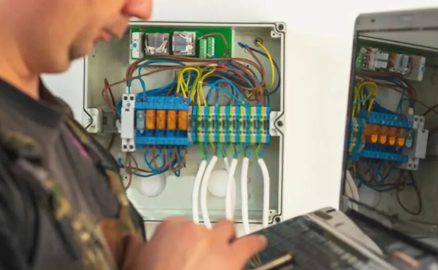
Electrical circuits are the backbone of modern technology, facilitating the operation of countless devices and systems across diverse sectors. These circuits, whether simple or complex, are designed to perform specific functions, from lighting our homes to powering sophisticated communication networks. Understanding their applications provides insight into how electrical energy is harnessed for practical use.
| Application | Circuit Type | Specific Function |
|---|---|---|
| Residential Wiring | Parallel | Power distribution, lighting, and appliance operation |
| Automotive Electronics | Mixed(Series and Parallel) | Engine control, lighting, accessories, and infotainment |
| Computer Systems | Complex integrated circuits | Data processing, storage, and communication |
| Communication Devices | RF, Analog and Digital circuits | Signal transmission and reception, data processing |
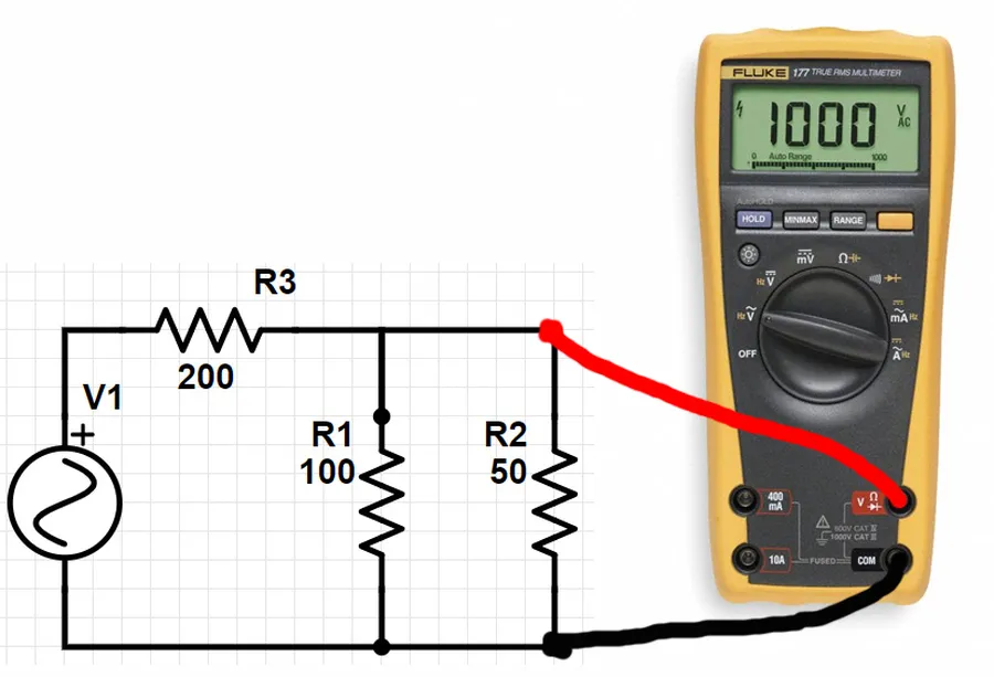
Effective troubleshooting of electrical circuits is crucial for maintaining functionality and safety. Common issues arise from faults that interrupt current flow or cause excessive current, including open circuits, short circuits, and component failures. Identifying these faults using a systematic approach and appropriate tools like a multimeter is essential for quick and safe repairs.
The multimeter is the primary tool for circuit troubleshooting. It measures voltage, current, and resistance, allowing identification of the specific fault type and location. Proper usage of a multimeter includes selecting the correct measurement function and range and understanding how to interpret the readings accurately. Safety precautions, such as ensuring the circuit is de-energized before taking measurements, are imperative.
| Issue | Symptoms | Multimeter Test | Possible Causes |
|---|---|---|---|
| Open Circuit | No current flow; zero voltage across load. | Measure high resistance across the break; measure voltage across the open. | Broken wire, loose connection, faulty switch, burned out component. |
| Short Circuit | Excessive current flow; low or no voltage across load; potential overheating or fuse blow. | Measure low resistance across the shorted path; measure increased current flow. | Insulation failure, improper connections, physical damage to wiring. |
| Component Failure | Erratic circuit behavior or complete malfunction. | Measure component value to ensure it is within tolerances; test functionality of the component. | Overvoltage, overcurrent, overheating, age, manufacturing defect. |
| Loose Connections | Intermittent or fluctuating circuit behavior. | Measure voltage and resistance across the connection; test continuity. | Poorly installed wiring, corroded contacts, physical damage to terminals. |
This section addresses common queries regarding electrical circuits, providing concise and authoritative answers to enhance understanding of fundamental concepts.
Building upon fundamental principles, advanced electrical circuit concepts delve into the complexities of alternating current (AC) circuits, impedance, resonance, and filtering, which are crucial for more sophisticated electronic applications. Furthermore, understanding the basics of digital circuits provides the foundation for modern computing and digital communication systems.
Here's an overview of these key concepts:
Electrical circuits, the intricate pathways of electrical current, form the backbone of our modern technological infrastructure. From the simple on/off switch to complex microprocessors, understanding the fundamentals of electrical circuits allows us to better appreciate and control the forces that power our world. By grasping the core concepts of circuit elements, types, and analysis methods, we can begin to see how these fundamental electrical pathways play a vital role in everything that defines modern life and continue to inspire innovation and progress. Through continued exploration and innovation in electrical circuits, we will continue to unlock even greater possibilities in the field of electricity and its various applications.

