In the world of electronics, a tiny component often plays a pivotal role: the 0.1 uF capacitor. Like the silent guardians of our devices, these capacitors ensure stable operation by filtering out unwanted noise. From smartphones to complex industrial machinery, understanding the 0.1 uF capacitor is essential for anyone diving into the fascinating realm of circuits and electrical engineering. This article demystifies this ubiquitous component and its vital role.
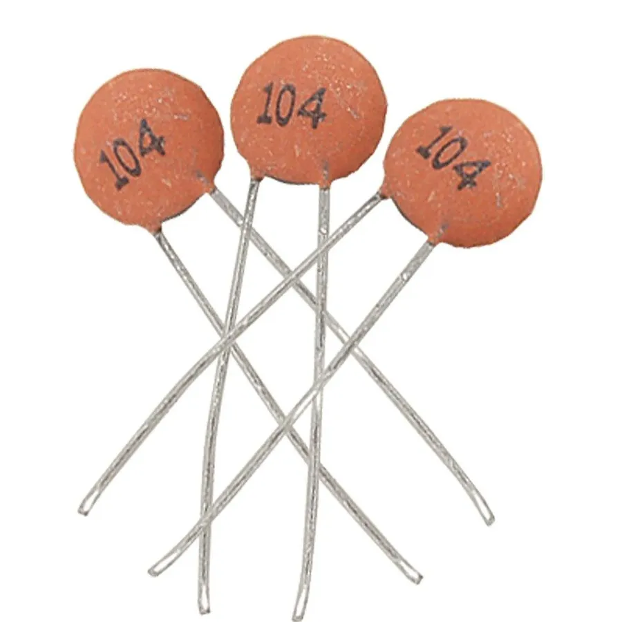
A 0.1 uF capacitor, also denoted as 0.1 microfarad or 100 nanofarad (100nF), is a fundamental passive electronic component designed to store electrical energy within an electric field. This specific capacitance value is widely utilized in diverse applications, with a primary focus on decoupling and bypassing high-frequency noise in electronic circuits.
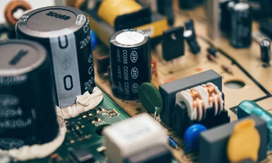
0.1 uF capacitors are fundamental in electronic circuit design, primarily functioning as decoupling capacitors in power distribution networks. They serve as miniature energy reservoirs placed strategically near integrated circuits (ICs) to mitigate voltage fluctuations and high-frequency noise, ensuring stable and reliable operation of sensitive electronic components. This role of 'decoupling' is crucial for preventing power supply noise from propagating into the ICs and causing signal corruption.
When a digital circuit switches states, it draws current in rapid pulses, causing voltage fluctuations on the power supply line. Without decoupling capacitors, these fluctuations can cause unstable behavior of the IC and its neighboring components. By placing a 0.1uF capacitor close to the power pin of an IC, it acts like a local charge storage, smoothing out the voltage spikes, and providing a stable voltage rail for the IC to operate. This ensures that other circuits connected to the same power source are isolated from those voltage transients, hence decoupling.
In addition to decoupling, 0.1 uF capacitors are also used for bypassing high-frequency signals to ground. These capacitors present a low impedance path for high frequency noise signals to go to ground, reducing the impact of this noise on the desired signals. This function is particularly useful in high-speed digital circuits where parasitic capacitances and inductances can cause unwanted interference.
The effectiveness of a 0.1uF capacitor is directly related to its proximity to the IC's power pin. The shorter the trace length, the lower the inductance, and the more efficient the decoupling. These concepts of decoupling and bypassing are foundational for ensuring reliable and noise-free operation of many digital and analog electronic circuits.
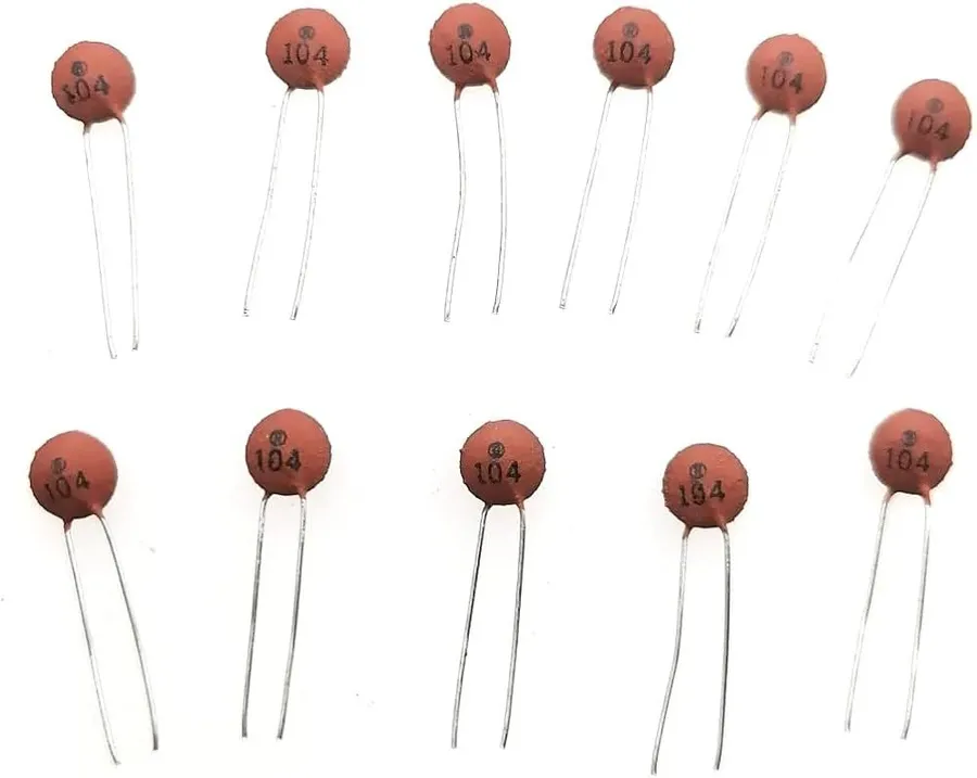
While all 0.1 uF capacitors share the same capacitance value, their physical and material characteristics vary significantly, impacting their suitability for different applications. These variations include the dielectric material, construction method, and physical size. For decoupling applications, ceramic capacitors are often preferred, but other types might be more appropriate in other designs.
| Capacitor Type | Dielectric Material | Key Characteristics | Typical Applications | Suitability for Decoupling |
|---|---|---|---|---|
| Ceramic Capacitors | Ceramic (e.g., X7R, C0G/NP0) | Small size, good high-frequency response, low cost | Decoupling, bypassing, general-purpose | Excellent |
| Film Capacitors | Polyester, polypropylene | Better temperature stability, higher voltage ratings, good accuracy | Power supplies, audio circuits, high-precision applications | Good for high power decoupling, not a first choice for general purpose |
| Electrolytic Capacitors | Aluminum oxide, tantalum pentoxide | High capacitance values, polarized, higher ESR, larger size | Bulk energy storage, power supply filtering, not good for high-frequency decoupling | Not suitable for high-frequency decoupling |
The prevalence of the 0.1 uF capacitor in decoupling applications is not arbitrary; it arises from a careful balance of practical considerations and engineering requirements. This value effectively addresses the need to filter out high-frequency noise while also storing enough charge to respond to transient power fluctuations. It's a standard choice close to the VCC pin of integrated circuits, ensuring stable and reliable operation.
The selection of 0.1uF as a standard decoupling capacitor is due to the following key reasons:
While 0.1uF is a common standard, it's crucial to note that the ideal capacitor value can vary based on the specific needs of the circuit. More specialized designs may require different values, which may be higher or lower depending on the noise frequency range. A detailed analysis of the circuit requirements is needed before making an appropriate decision for specific high frequency filtering needs.
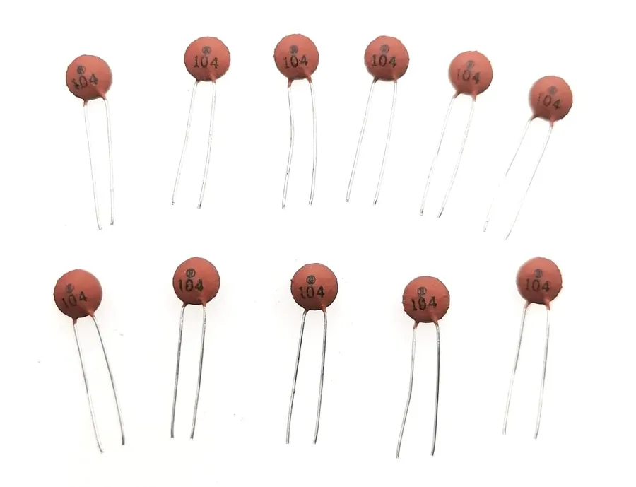
Ceramic capacitors, particularly those of smaller size, often employ a three-digit numerical code to denote their capacitance value, a practice stemming from space constraints and industry standardization. The '104' marking is a ubiquitous code found on 0.1 uF ceramic capacitors, signifying a capacitance of 100 nanofarads (nF), equivalent to 0.1 microfarads (uF), and understanding this coding system is essential for correct component identification and selection.
| Digit Code | Calculation | Result | Unit |
|---|---|---|---|
| 104 | 10 x 10^4 | 100,000 | picofarads (pF) |
| 100,000 pF / 1000 | 100 | nanofarads (nF) | |
| 100 nF / 1000 | 0.1 | microfarads (uF) |
The first two digits of the code represent the significant figures of the capacitance value, and the third digit specifies the multiplier, which is a power of ten. Consequently, a ‘104’ code translates to 10 multiplied by 10 to the power of 4, which equals 100,000 picofarads (pF). Conversion to nanofarads and microfarads is crucial for practical application, yielding 100nF or 0.1uF, respectively.
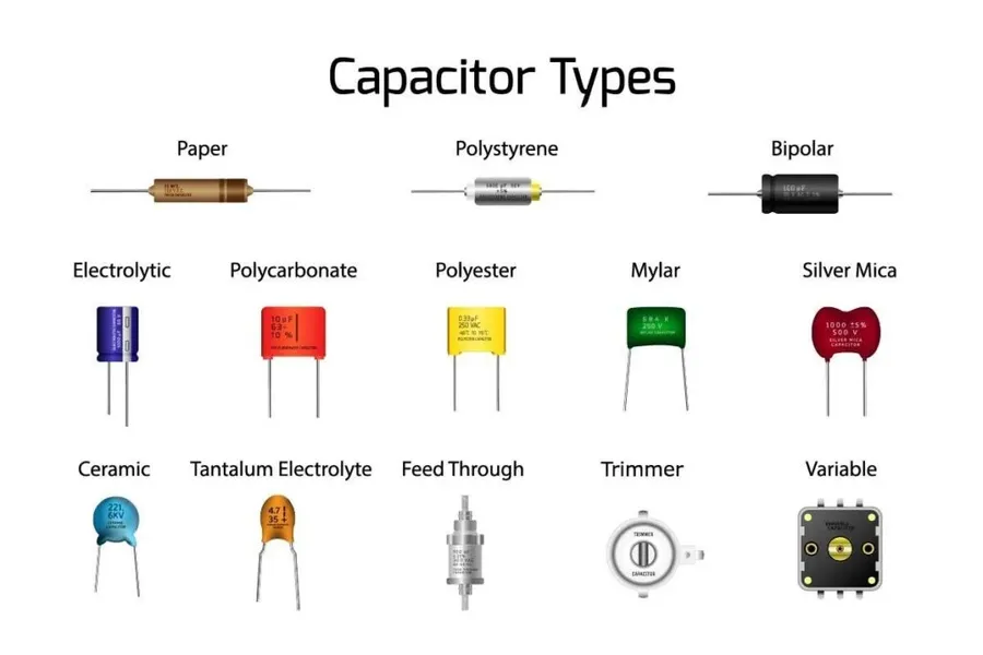
The 0.1 uF capacitor is a ubiquitous component in modern electronics, playing a crucial role in ensuring stable and reliable circuit operation. Its primary function revolves around mitigating noise and fluctuations in various electronic systems. These capacitors are integral in power distribution networks, signal processing, and timing applications.
Selecting the appropriate 0.1 uF capacitor is crucial for optimal circuit performance. This process involves considering several key electrical and physical parameters to ensure the capacitor functions effectively within its intended environment and application. The primary concerns revolve around voltage, temperature, tolerance, size, and material composition, each of which impacts the capacitor's operational characteristics and suitability.
| Parameter | Description | Selection Considerations |
|---|---|---|
| Voltage Rating | The maximum voltage the capacitor can safely handle without dielectric breakdown. | Choose a rating at least twice the circuit's operating voltage to ensure reliability and safety margin. |
| Temperature Rating | The range of temperatures within which the capacitor will operate reliably. | Select a capacitor rated for the temperature range of the application's environment. Exceeding this range may cause damage or performance issues. |
| Tolerance | The permissible deviation from the nominal 0.1uF capacitance value. | Tighter tolerances are essential for precision applications where small variations in capacitance can have significant impacts. |
| Physical Size | The dimensions and case size of the capacitor. | Ensure the capacitor's physical dimensions match the available PCB footprint and space constraints. This includes both surface mount (SMD) and through-hole components. |
| Material Type | The dielectric material used in the capacitor construction, such as ceramic, film, or electrolytic. | For decoupling applications, ceramic capacitors (particularly multilayer ceramic capacitors - MLCCs) are typically preferred due to their excellent high-frequency characteristics. Film capacitors are suitable for situations requiring higher voltage or better temperature stability. Electrolytic types are usually unsuitable for decoupling because of their construction and higher ESR. |
This section addresses common queries about 0.1 uF capacitors, clarifying their function, identification, and usage in electronic circuits. Understanding these aspects is crucial for effective circuit design and troubleshooting.
While the 0.1 uF capacitor is a ubiquitous choice for decoupling, it's crucial to recognize that it's not a universal solution. The optimal capacitor value for decoupling is dependent on the frequency range of the noise being targeted for suppression. Lower capacitance values are generally more effective at attenuating higher frequency noise, which may lead to the selection of different capacitor values depending on the specific application. The selection of capacitance is a matter of balancing the need to filter high frequencies and the need to store sufficient charge to respond to power spikes.
| Capacitance Value | Typical Use Case | Frequency Range Effectiveness | Notes |
|---|---|---|---|
| 1 nF | High-speed digital circuits, very high frequency noise | Very High | Effective for very fast signal transitions and high frequency noise |
| 10 nF | High-speed digital circuits, higher frequency noise | High | Good for suppressing high frequency transients. |
| 0.1 uF (100 nF) | General-purpose decoupling, microcontroller applications | Medium | Standard for decoupling most digital circuits. |
| 1 uF | Lower frequency noise, bulk decoupling | Low | Better at lower frequencies and typically used in parallel with lower values for wide frequency coverage |
| 10 uF or higher | Bulk capacitance for power supply stabilization | Very Low | Used to maintain a stable voltage rail and are not effective for high frequency filtering |
Selecting the optimal decoupling capacitor requires a thorough understanding of the target system's noise profile. The frequency of the noise and the current demand requirements of the device should be carefully considered before making the selection.
The 0.1 uF capacitor is a small but mighty workhorse in electronics. Its primary role in decoupling and bypassing ensures stable operation by smoothing out power variations and filtering noise. While other capacitor values are available, the 0.1uf remains a common and indispensable part of countless electronic designs due to its effectiveness in high-frequency applications and ease of integration. As technology advances, the 0.1 uF capacitor will continue to play a vital role in ensuring our electronics perform reliably, and understanding its role will be essential for anyone looking to design stable and effective circuits.

