Understanding Zener Diodes: How They Stabilize Voltage
2025.01.20
In our increasingly electronic world, stable voltage is paramount for reliable operation of devices, and zener diodes play a crucial role in achieving that. Like a reliable gatekeeper, a zener diode ensures that voltage supplied to electronic circuits remains constant despite fluctuations in the input. This article demystifies the zener voltage regulator, explaining how it works, its applications, and offering essential insights for both beginners and experienced electronics enthusiasts. Let's delve into how this seemingly simple component is so pivotal to modern electronics.
Zener Diode Fundamentals
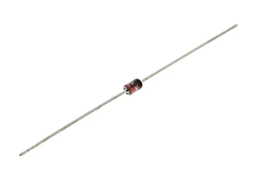
Zener diode component
Zener diodes are semiconductor devices specifically engineered to operate in the reverse breakdown region, a characteristic that distinguishes them from standard diodes. Unlike conventional diodes that block reverse current until damaged by excessive voltage, Zener diodes are designed to conduct current in reverse bias once a specific voltage threshold, known as the Zener voltage, is reached. This unique behavior makes them invaluable for voltage regulation and protection applications.
Feature
Standard Diode
Zener Diode
Reverse Bias Behavior
Blocks current until breakdown (undesired)
Conducts current at a specific Zener voltage (desired)
Primary Function
Rectification (unidirectional current flow)
Voltage regulation and reference
Breakdown Region
Generally avoided as it's destructive
Designed to operate within this region
The key distinction lies in the doping levels and construction of the Zener diode. Standard diodes are heavily doped on one side, forming a sharp junction that is intended to conduct current in one direction. Zener diodes, however, have a controlled doping level that allows for reliable and predictable reverse breakdown at the designed Zener voltage, without destruction. When a reverse voltage exceeding the Zener voltage is applied, the device enters the breakdown region, and the current increases rapidly with very little increase in voltage, holding the voltage across the diode nearly constant. This mechanism is what allows them to act as a voltage regulator.
The Zener Diode as a Voltage Regulator
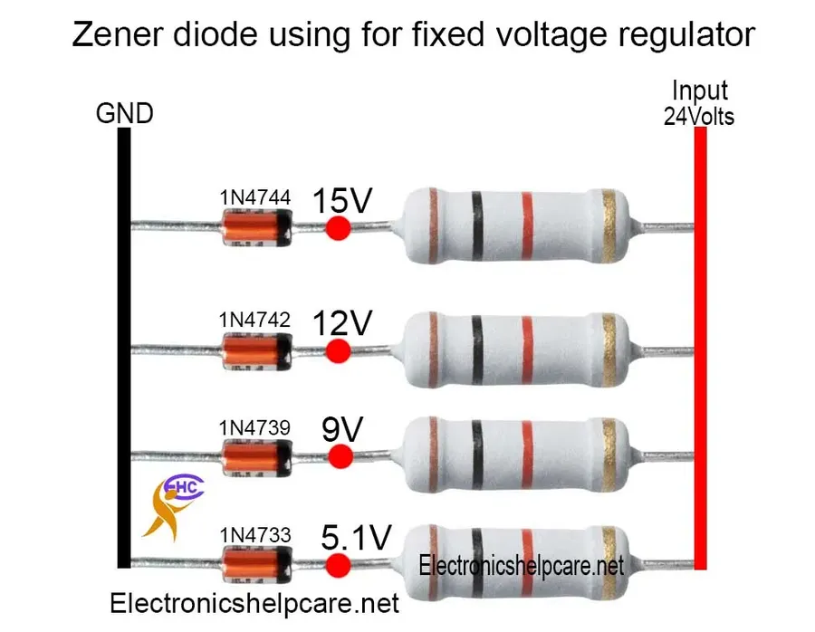
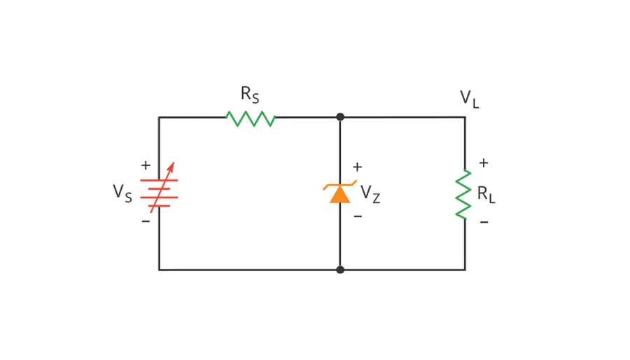
Zener diode regulator circuit
Zener diodes, when operated in reverse bias, exhibit a unique ability to maintain a nearly constant voltage across their terminals, a characteristic that makes them suitable as voltage regulators. This behavior is fundamentally different from standard diodes, which typically block current in reverse bias until reaching destructive breakdown. The Zener diode, however, is designed to operate in this controlled breakdown region, effectively acting as a shunt regulator.
As a shunt regulator, the Zener diode is placed in parallel with the load. When the input voltage rises above the Zener voltage (Vz), the diode begins to conduct current, effectively 'shunting' excess current away from the load and maintaining the load voltage at approximately Vz. The series resistor in the circuit plays a crucial role in limiting the current flowing through the Zener diode to prevent damage and to allow the circuit to function correctly. The relationship between the input voltage (Vin), the Zener voltage (Vz), and the load resistance (RL) is crucial for proper circuit design.
The fundamental operating principle involves the following relationships:
The series resistor (Rs) has an important function for circuit operation; it must be selected such that the Zener diode current doesn't exceed its ratings, and that the regulation can be maintained for different load conditions.
Zener Diode Circuit Design
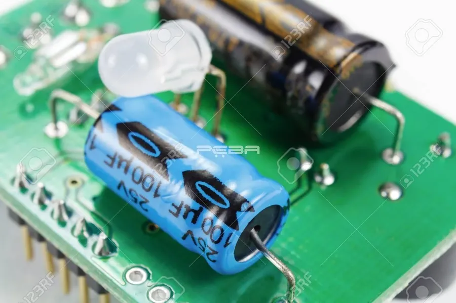
Zener diode on PCB
Designing a Zener diode voltage regulator involves a systematic approach to ensure stable output voltage and component longevity. The core of the design is the inclusion of a series resistor that limits current and protects the Zener diode from overcurrent. This section provides a step-by-step guide to designing a basic regulator circuit, with a focus on calculating the series resistor and selecting appropriately rated components.
The basic Zener diode regulator circuit is a shunt regulator, where the Zener diode is connected in parallel with the load. The process for designing a basic Zener diode voltage regulator circuit involves several key steps:
Determine Input Voltage (V_in): Identify the range of input voltage the circuit will encounter. This is crucial for calculating the appropriate series resistor value.
Select Zener Voltage (V_z): Choose a Zener diode with the desired regulated output voltage (Vz). Ensure the selected Vz is appropriate for the application's needs.
Determine Load Current (I_load): Calculate the maximum current expected to be drawn by the load connected to the voltage regulator. This load current will influence the calculation of series resistor.
Calculate Series Resistor (R_s): The series resistor (Rs) is determined using the following formula: Rs = (Vin_min - Vz) / (Iz_min + Iload_max), where Vin_min is the minimum input voltage, Vz is the zener voltage, Iz_min is the minimum zener current needed to stay in the breakdown region, and Iload_max is the maximum load current. The maximum series resistor (Rs_max) is determined using the following formula: Rs_max = (Vin_max - Vz) / Iz_min. The series resistor should not be lower than Rs and should not be higher than Rs_max. Generally it is recommended to use the Rs.
Calculate Zener Diode Power Dissipation (Pz): The maximum power dissipation for the Zener diode is calculated as Pz = Vz * (Iz_max), where Iz_max = (Vin_max - Vz)/Rs. Ensure that the selected Zener diode has a power rating greater than this calculated value to prevent overheating and failure. The power dissipation of the Zener diode increases with the increasing input voltage and decreasing load resistance.
Select Standard Component Values: Choose the nearest standard value for the series resistor. If a suitable standard value is not available, it's better to choose a lower value than a higher one, to make sure the Zener diode has enough current and the voltage is correctly regulated. Check component datasheets carefully for correct power and voltage ratings.
When selecting the series resistor, it is critical to ensure the series resistor's power rating exceeds the calculated power dissipation to prevent component failure. A higher power rating can improve long term reliability.
While this method focuses on the basic calculations, consider using simulation software for complex circuits or extreme operating environments. This approach allows you to analyze a range of operating conditions that may not be easily calculated manually, such as changes in voltage and load resistance.
Zener Diode V-I Characteristics
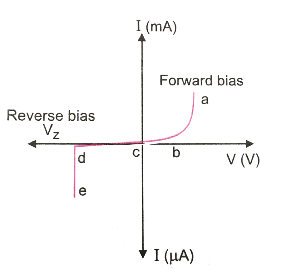
Zener diode IV curve
The voltage-current (V-I) characteristic curve of a Zener diode is crucial for understanding its voltage regulation capabilities. Unlike a standard diode, the Zener diode is designed to operate in reverse bias, where, beyond a certain voltage, the 'breakdown' or Zener region, it exhibits a stable voltage drop over a range of current. The 'knee' of this curve is where the reverse current increases rapidly with a minimal change in reverse voltage, which is the operational zone for voltage regulation.
The V-I curve of a Zener diode is characterized by three main regions: forward bias, reverse bias (below breakdown), and reverse bias (breakdown or Zener region). In forward bias, it behaves like a normal diode, allowing current to flow when the anode is more positive than the cathode. In reverse bias, below the breakdown voltage, only a small leakage current flows. However, once the reverse voltage exceeds the Zener voltage, the diode enters the breakdown region, maintaining a relatively constant voltage across it despite variations in the reverse current.
The 'knee' region of the V-I curve is of critical importance because it defines the point at which the Zener diode begins to regulate voltage. The steep slope of the curve in the breakdown region indicates that a small change in voltage results in a significant change in current, allowing the zener diode to act as a shunt regulator by diverting excess current to maintain voltage stability. This makes the Zener diode valuable for providing a stable voltage reference in electronic circuits.
Zener Voltage (V)
Typical Applications
3.3V
Low-voltage logic circuits, microcontroller power supply
5.1V
TTL logic circuits, reference voltages for analog circuits
6.2V
Precision reference voltage for analog applications
12V
Automotive electronics, higher-voltage logic circuits, general purpose regulation
Zener diodes, leveraging their unique reverse breakdown characteristic, are indispensable in various circuit applications, primarily for voltage regulation, overvoltage protection, and signal clipping. These applications exploit the diode's ability to maintain a relatively constant voltage across its terminals when operated in the reverse breakdown region.
Overvoltage Protection Zener diodes are frequently used to protect sensitive electronic components from excessive voltage spikes. When the voltage exceeds the Zener diode's breakdown voltage, the diode conducts, shunting excess current to ground and preventing damage to downstream components. This is particularly useful in power supply circuits and interfaces with external environments prone to surges.
Precision Reference Voltage Generation Zener diodes provide a stable reference voltage crucial for analog circuits, such as comparators and analog-to-digital converters (ADCs). By operating the diode in its breakdown region, a consistent and reliable voltage reference point is established. This consistent voltage is fundamental for accurate signal processing and control applications. They are chosen for their stability and low temperature coefficient compared to other voltage reference methods. This application is critical in instrumentation and measurement systems.
Signal Clipping Zener diodes can be used to limit the amplitude of a signal, effectively clipping the signal at a predetermined voltage level. By connecting a Zener diode with an appropriate breakdown voltage across the signal path, voltage peaks can be clipped, preventing signal distortion or damage to following circuitry. This method provides a simple way to limit voltage swings, which can protect subsequent circuit stages, or create unique signal properties.
Comparator Reference In comparator circuits, Zener diodes provide a stable reference voltage against which an input voltage is compared. This is a very specific application within reference voltage generation, as the application is to enable the comparator to make precise decisions based on this stable reference, rather than merely providing a reference. For instance, in overvoltage detection the zener will provide a trigger point, allowing the comparator to activate an alarm or protection circuit when the voltage exceeds the breakdown voltage.
Limitations of Zener Diode Regulators
While Zener diodes offer a simple and cost-effective solution for voltage regulation, their application is limited by several key factors, primarily related to power dissipation, efficiency, and suitability for high-current loads. These limitations must be carefully considered when designing circuits.
Power Dissipation Zener diode regulators function by shunting excess current to ground when the input voltage exceeds the Zener voltage. This process dissipates power as heat, which can be problematic, especially with larger voltage differences between input and regulated output, or with higher current loads. The power dissipated is calculated by P = (Vin - Vz) * Iz, where Vin is the input voltage, Vz is the Zener voltage, and Iz is the current through the zener diode. Inefficient power dissipation can lead to excessive heat generation, which can damage the diode and other nearby components if not managed correctly.
Efficiency The shunt regulator nature of zener diode circuits makes them inherently inefficient. Power is wasted as heat in the series resistor and the Zener diode when the load current is less than the maximum current. This wasted power, especially at high currents, makes Zener regulators less suitable for battery-powered devices where energy conservation is critical. The efficiency decreases as the difference between the input voltage and zener voltage increases because a larger voltage drop requires a larger current to be shunted to maintain the output voltage, increasing overall losses.
Limited Current Capacity Zener diodes are not designed to handle high current loads directly, primarily due to the power dissipation limitations. While the Zener diode can regulate the voltage, its ability to source current to the load is directly limited by its power rating. If the current required by the load exceeds what the Zener diode can handle, it can lead to damage or inaccurate voltage regulation. In high-current applications, more efficient voltage regulator circuits (like linear regulators or switching regulators) are preferred.
Temperature Sensitivity The Zener voltage has a temperature coefficient, meaning that it will shift slightly with changes in temperature. For some Zener diodes, the voltage will increase with temperature, while it may decrease for others, depending on their breakdown mechanism and manufacturing properties. This characteristic makes them less suitable for applications where very precise and temperature-stable voltage references are needed. Moreover, the Zener diode's operating junction temperature must stay within the manufacturer's recommended range, and the external heat sinks may be required in high-power applications.
Zener Voltage Regulator vs. Other Voltage Regulators
Zener diode regulators, while simple, are not the only option for voltage regulation. This section compares them against linear and switching regulators, highlighting their respective strengths and weaknesses to guide selection for specific applications. Choosing the right regulator is crucial for circuit performance and efficiency.
Feature
Zener Diode Regulator
Linear Regulator
Switching Regulator
Efficiency
Low, especially with large input-output voltage difference
Moderate, depends on input-output voltage difference
High (typically 70% to 95%)
Power Dissipation
High, significant heat generation
Moderate, can still produce significant heat
Low, less heat generation
Output Current
Limited, typically for low-current applications
Moderate, suitable for a wide range of currents
High, can provide substantial current
Complexity
Simple, requires minimal components
More complex than Zener, simpler than switching
Complex, requires more components
Cost
Low, inexpensive components
Moderate, generally inexpensive ICs
High, more expensive components
Noise
Low noise
Low noise
Higher noise due to switching, requires filtering
Typical Applications
Low current reference voltage, simple protection circuits, clipping circuits
General-purpose applications, powering ICs and microcontrollers
High-power applications, such as power supplies for computers and high-power devices
Advantages
Simplicity, low cost
Moderate efficiency, low noise, good stability
High efficiency, low heat generation
Disadvantages
Low efficiency, limited current, temperature sensitivity
Lower efficiency at high input-output difference, power dissipation
Higher cost, more complex circuitry, noise
Zener diode regulators are most suitable for applications where simplicity and low cost are paramount and the current requirements are minimal, such as in reference voltage circuits or basic over-voltage protection. Linear regulators are a more versatile option, offering better efficiency than zener regulators, and are commonly used for general-purpose power regulation in electronic devices. Switching regulators are preferred for applications that require high efficiency and high current output.
Frequently Asked Questions About Zener Voltage Regulators
This section addresses common questions regarding Zener diode voltage regulators, providing concise answers based on fundamental principles to enhance understanding.
What is the role of a Zener diode in voltage regulation? A Zener diode, when reverse-biased, maintains a relatively constant voltage across its terminals once the breakdown voltage is reached. This characteristic is used to create a shunt voltage regulator, where it diverts excess current away from the load to maintain a stable output voltage. It's important to remember that the Zener diode doesn't 'regulate' by adjusting itself; it's a passive element that exploits its unique voltage-current behavior.
What is the primary disadvantage of a Zener voltage regulator? The main drawback of a Zener diode regulator is its inefficiency, especially at higher current levels. Because it operates as a shunt regulator, it dissipates excess power as heat. This limitation also makes it unsuitable for regulating high-current loads, where the dissipated power can become considerable and damage the diode or the surrounding circuit.
What occurs if a Zener diode fails? If a Zener diode fails, it typically shorts out or opens up. A short circuit could lead to an overcurrent situation, potentially damaging other components in the circuit. An open circuit would mean that the regulation is lost, and the load receives the full (unregulated) input voltage. It's crucial to protect Zener diodes with a properly sized series resistor to limit the current and prevent failure.
Explain the Zener effect in simple terms? The Zener effect is a quantum mechanical phenomenon that occurs in heavily doped semiconductors. When a reverse voltage is applied, a strong electric field develops in the depletion region, allowing electrons to tunnel from the valence band to the conduction band. This tunneling creates reverse current and occurs at a specific reverse voltage for a given diode; this is the Zener breakdown voltage. Unlike avalanche breakdown, the Zener effect can occur at lower voltages.
How does temperature affect the zener voltage? The zener voltage can shift with changes in temperature. The degree of this shift varies depending on the specific Zener diode and its breakdown voltage. Typically, lower voltage Zener diodes (below 5V) exhibit a negative temperature coefficient, meaning their breakdown voltage decreases with increasing temperature. Higher voltage Zener diodes tend to exhibit a positive temperature coefficient.
Are Zener diodes efficient as voltage regulators? Zener diodes are not highly efficient as voltage regulators, especially compared to linear or switching regulators. They work by shunting excess current to ground, which dissipates power as heat. For low-power, low-current applications, they are acceptable, but for higher power applications, they can become very inefficient due to the significant power dissipation. The primary role is to maintain a desired voltage, with efficiency being secondary.
What is the purpose of the series resistor in a Zener diode regulator? The series resistor in a Zener diode voltage regulator is crucial for limiting the current flow through the diode and the overall circuit. It ensures that the Zener diode is operating within its safe operating range, preventing damage from excessive current. Without it, the Zener diode could be destroyed from excessive power dissipation. The resistor also helps to convert the excess voltage into current that flows through the Zener diode, allowing the load to be stabilized at the Zener voltage.
Practical Tips for Using Zener Diodes
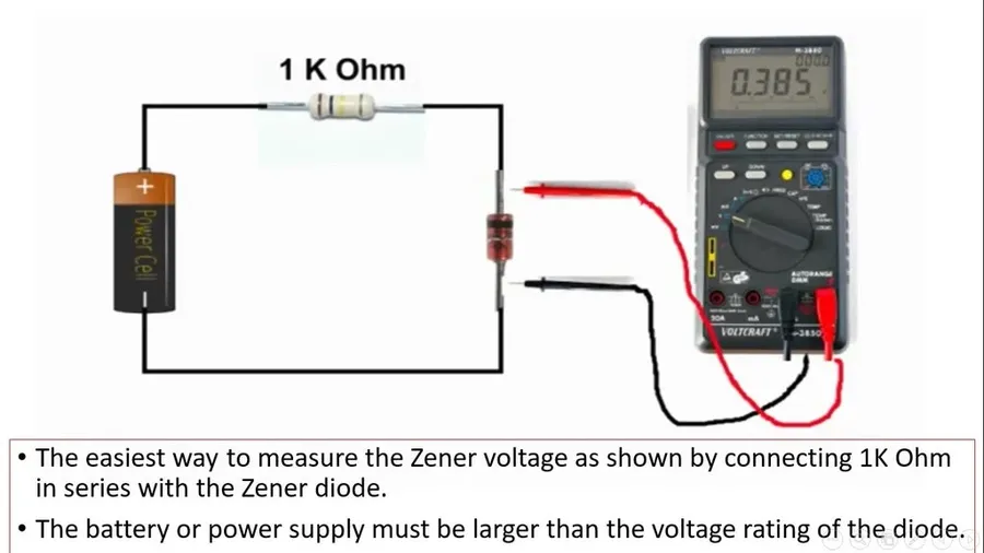
Measuring Zener diode
Selecting the correct Zener diode for a specific application requires careful consideration of several factors to ensure reliable voltage regulation and prevent component failure. A thorough understanding of the diode's characteristics and the circuit's operating conditions is essential for optimal performance.
Consult the Datasheet Always begin by thoroughly reviewing the manufacturer's datasheet for the specific Zener diode. This document provides critical information such as the Zener voltage (Vz), the maximum power dissipation (Pmax), the dynamic impedance, and the temperature coefficient of the Zener voltage. Verify the test conditions used to establish these values to ensure they are consistent with your application requirements.
Power Dissipation A critical parameter is the maximum power dissipation rating (Pmax). Calculate the power that the Zener diode will need to dissipate in your circuit, particularly under worst-case conditions such as maximum input voltage and minimum load resistance. Ensure that the calculated power dissipation remains well below the Pmax rating specified in the datasheet to avoid overheating and potential failure. The dissipated power can be calculated using: P = (Vz * Iz), where Iz is the current flowing through the zener diode.
Zener Voltage Selection Choose a Zener diode with a Zener voltage (Vz) that is appropriate for the desired regulated voltage. Remember that the specified Zener voltage is usually a nominal value and can vary slightly between devices and with temperature. A tight tolerance Zener diode is often preferred for critical applications.
Temperature Coefficients Zener voltage exhibits a temperature coefficient that describes how the Zener voltage changes with temperature. It is crucial to note that Zener diodes with lower breakdown voltages (below approximately 5V) tend to have a negative temperature coefficient and those with higher breakdown voltages have a positive temperature coefficient. Determine if the expected temperature range of operation might cause a critical variation in the regulated voltage. For temperature-sensitive applications, choose Zener diodes with minimal temperature coefficients or employ temperature compensation circuits.
Series Resistor Calculation The series resistor is critical for limiting the current through the Zener diode. Calculate the value of the series resistor such that under minimum input voltage and maximum load current, the Zener diode is in the breakdown region. However, under maximum input voltage and minimum load current, the current through the Zener diode does not exceed its maximum current rating (Izmax). Use the following formulas to approximate the resistor value: R = (Vin_min - Vz)/I_load_max and check that I_zmax > (Vin_max - Vz)/R - I_load_min
Dynamic Impedance The dynamic impedance of a zener diode represents its resistance to changes in current when operated in its breakdown region. This parameter impacts the load regulation of the zener diode voltage regulator. A lower dynamic impedance will result in a more stable output voltage with load changes. For highly accurate voltage references or noise-sensitive applications, selecting a Zener diode with a low dynamic impedance is crucial.
Consider Failure Modes Understanding the failure modes of a Zener diode is critical. Zener diodes typically fail short when their maximum power dissipation limits are exceeded. Include a properly sized series resistor that limits the current in the event of a zener diode failure. Also consider placing a fuse in series with the zener diode to prevent damage to the rest of the circuit due to a zener failure.
Practical Considerations When assembling the circuit, use proper heat sinking techniques if the Zener diode is expected to dissipate a significant amount of power. Verify all connections before applying power and monitor the diode temperature and the output voltage during operation. In complex circuits, test the voltage regulation under different load conditions to verify the proper functioning of the zener diode regulator.
The zener voltage regulator, using the unique characteristics of the zener diode, is a foundational component for maintaining stable voltage levels in countless electronic applications. From basic hobbyist circuits to complex industrial power supplies, the zener diode's ability to provide precise voltage reference is invaluable. Understanding its capabilities, limitations, and design considerations is crucial for any electronics professional. As technology advances, the principles of zener voltage regulation remain ever relevant, demonstrating the enduring importance of understanding this fundamental electronic component. Further exploration of advanced regulation techniques and applications builds on the core concepts laid out in this article.