Imagine a city's water pipes: a capacitor acts like a temporary water tank, storing energy, while a resistor is like a narrow section restricting water flow. In electronics, a capacitor and resistor in parallel form a vital circuit element, creating a dynamic interplay of energy storage and dissipation. This article will unravel the mysteries of parallel RC circuits, covering their behavior, calculations, and real-world applications, bridging theoretical concepts with everyday electronic devices.
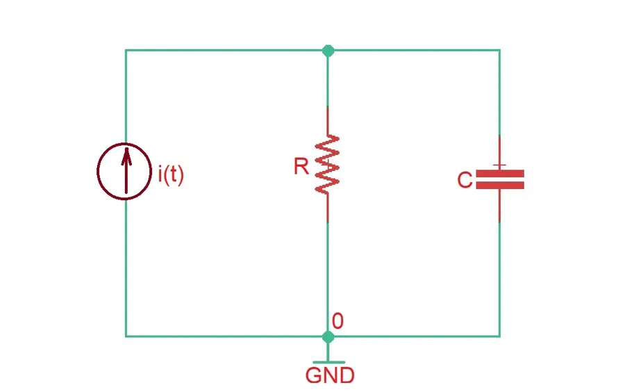
Parallel RC circuits, characterized by a resistor and a capacitor connected side-by-side, exhibit a fundamental electrical behavior where the voltage across both components is identical, while the total current divides between them. This arrangement forms the cornerstone of various electronic applications, each component playing a distinct role in circuit functionality. Understanding these core concepts is crucial for designing and analyzing a variety of electronic circuits.
In a parallel RC circuit, the applied voltage is equally present across both the resistor and the capacitor. This is a defining characteristic of parallel circuits. The current, however, splits into two paths. The resistor allows current flow in proportion to the applied voltage based on Ohm's Law (I = V/R), while the capacitor’s current is influenced by how fast the voltage across it changes. The capacitor stores electrical energy and its current behavior is linked to the rate of change of the voltage across it.
The foundational principles of these networks are governed by basic electrical laws, such as Kirchhoff’s laws and the relationships defining resistors and capacitors: Ohm's Law (V=IR) for resistors and the capacitor’s constitutive equation I=C(dV/dt) where C is the capacitance and dV/dt represents rate of voltage change. These equations allow circuit behavior to be quantitatively analyzed. The schematic of parallel RC circuit includes standard circuit symbols. The resistor is represented by a zigzag line, while the capacitor uses two parallel lines. The input voltage source and all wiring are depicted with solid lines and connection points are indicated with dots.
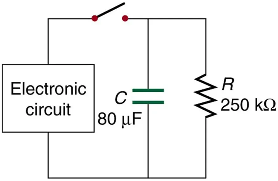
In a parallel RC circuit, the capacitor and resistor exhibit distinct behaviors that collectively influence the circuit's overall characteristics. The fundamental principle of a parallel circuit is that the voltage across each component is the same, while the total current divides between the branches. Understanding these individual behaviors is crucial for analyzing and designing circuits effectively.
A capacitor, ideally, blocks the flow of direct current (DC) and stores energy in an electric field formed by separated charge. When a DC voltage is applied, a capacitor rapidly charges and, once fully charged, effectively stops current flow. Conversely, a capacitor allows alternating current (AC) to pass through, with its opposition to AC current, known as capacitive reactance, decreasing as frequency increases. In a parallel RC circuit, the capacitor's charging and discharging behavior will affect how current flows within the circuit especially during transient periods.
A resistor, on the other hand, offers a fixed opposition to current flow regardless of the frequency, dissipating electrical energy as heat. In a parallel RC circuit, the resistor will continuously draw current based on Ohm's Law (I=V/R) where I represents current, V represents voltage, and R represents resistance. The resistor provides a steady path for current, contrasting with the capacitor's more dynamic behavior. The combined effect of these components determines the current and voltage relationships within the circuit. In summary, the resistor facilitates a constant current path that dissipates energy while the capacitor stores and releases energy which is dependent on frequency and voltage.
| Component | DC Behavior | AC Behavior | Energy Role |
|---|---|---|---|
| Capacitor | Blocks current flow after charging | Allows current flow, impedance decreases with frequency | Stores energy in electric field |
| Resistor | Allows constant current flow | Allows constant current flow | Dissipates energy as heat |
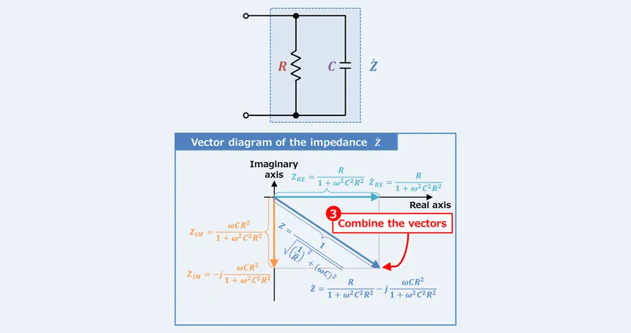
In parallel RC circuits, impedance is the total opposition to current flow, encompassing both resistance and reactance. Unlike pure resistance, which is constant across all frequencies, impedance in an RC circuit varies with frequency. This frequency dependence arises from the capacitor's reactance, which decreases as frequency increases. Understanding impedance is crucial for analyzing AC circuit behavior because it determines how a circuit responds to different signal frequencies.
| Parameter | Resistance (R) | Capacitive Reactance (Xc) | Impedance (Z) |
|---|---|---|---|
| Definition | Opposition to current flow, independent of frequency | Opposition to current flow, dependent on frequency | Total opposition to current flow, including R and Xc |
| Formula | R (Ohms) | 1/(ωC) = 1/(2πfC) (Ohms) | 1/Z = √((1/R)² + (ωC)² ) or Z = 1 / sqrt((1/R)^2 + (1/Xc)^2) (Ohms) |
| Frequency Dependence | No | Yes, decreases with increasing frequency | Yes, decreases with increasing frequency |
| DC Behavior | Constant resistance | Infinite reactance, acts as an open circuit | Equivalent to resistance, Z=R |
| AC Behavior | Constant resistance | Reactance decreases with increasing frequency, current can pass | Overall impedance decreases as frequency increases |
Key distinctions are apparent when considering DC versus AC behavior. At DC (0 Hz), the capacitor behaves as an open circuit, and the impedance of the parallel RC circuit is primarily determined by the resistor’s resistance, with total impedance approaching the resistance value. As the frequency increases, the capacitor's reactance decreases, allowing more AC current to flow. This results in the overall impedance of the parallel RC circuit decreasing. The formula for calculating the total impedance (Z) of a parallel RC circuit is given by: 1/Z = √((1/R)² + (ωC)² ), where R is resistance, C is capacitance and ω is the angular frequency (2πf).
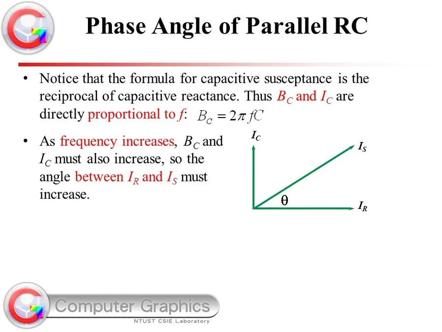
In a parallel RC circuit, the interplay between current and voltage is crucial, primarily due to the phase differences introduced by the capacitor. While the voltage across both the resistor and capacitor is identical in a parallel configuration, the current through each component exhibits a distinct phase relationship. Understanding these phase differences is fundamental to analyzing the circuit's overall behavior.
The current through the resistor (I_R) is in phase with the applied voltage (V), meaning they reach their maximum and minimum values at the same time. In contrast, the current through the capacitor (I_C) leads the voltage by 90 degrees. This phase shift occurs because the capacitor charges and discharges in response to the voltage change, rather than instantaneously following the voltage.
To determine the total current in a parallel RC circuit, one must consider both the magnitudes and the phase relationships of the individual currents. The total current (I_T) is not simply the sum of I_R and I_C, but rather their vector sum. This is because they are not in phase and this principle is typically visualized using phasor diagrams.
A phasor diagram represents these currents as vectors. The resistive current (I_R) is drawn along the horizontal axis (representing the phase of the voltage), and the capacitive current (I_C) is drawn along the vertical axis, leading by 90 degrees. The total current is the resultant vector, found using the Pythagorean theorem: I_T = sqrt(I_R^2 + I_C^2). The phase angle between the total current and voltage can be determined using trigonometric functions, specifically the tangent function, where tan(θ) = I_C / I_R.

Parallel RC circuits are fundamental building blocks in numerous electronic systems, leveraging the distinct properties of resistors and capacitors to achieve specific signal processing or power management goals. Their ability to filter, smooth, and divide signals based on frequency makes them invaluable in diverse applications.
Below are some prominent uses of parallel RC circuits:
These applications highlight the versatility of parallel RC circuits. By carefully selecting component values, engineers can tailor these circuits to meet specific design requirements.
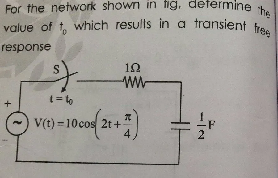
The transient response of a parallel RC circuit describes how the circuit behaves when a sudden change occurs, such as the application or removal of a voltage source. This analysis is crucial for understanding the dynamic behavior of such circuits, especially during the charging and discharging phases of the capacitor.
When a voltage source is applied to a parallel RC circuit, the capacitor begins to charge. Initially, the capacitor acts as a short circuit, allowing a significant current to flow. This current divides between the capacitor and the resistor. The current through the resistor is governed by Ohm's law, while the current through the capacitor is determined by the rate of change of voltage across it, as described by the equation: i(t) = C * dv(t)/dt. As the capacitor charges, the voltage across it increases exponentially, approaching the source voltage. The charging time is determined by the time constant τ, where τ = RC. After five time constants (5τ), the capacitor is considered fully charged.
When the voltage source is removed, the charged capacitor begins to discharge through the resistor. The capacitor's voltage decreases exponentially, and the discharge current also diminishes over time. The time constant τ, which is again equal to RC, governs the rate at which the capacitor discharges. The capacitor is considered fully discharged after 5 time constants (5τ). The equation v(t) = V0 * e^(-t/RC) describes the discharging voltage of the capacitor over time. Where V0 represents the initial voltage and v(t) represents the voltage at time t.
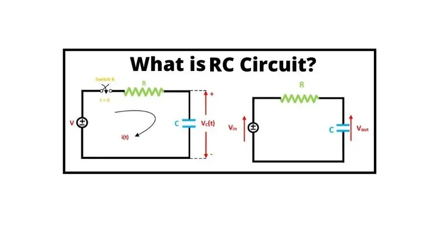
Designing effective parallel RC circuits requires careful selection of component values to achieve the desired performance characteristics. Key considerations include filtering requirements, desired time constants, component tolerances, and ensuring optimal circuit behavior for the intended application. Understanding these factors is critical to successful and reliable designs.
Component selection in parallel RC circuits hinges on understanding application-specific needs. The following practical tips guide the selection process:
By meticulously considering these design considerations, engineers can create parallel RC circuits that meet their exact application needs. This involves a detailed understanding of theoretical concepts and practical component limitations, leading to robust and reliable circuit behavior. Proper design ensures that the circuit will function as intended, delivering the desired electrical characteristics. Simulation and experimentation are vital for verifying designs before final implementation.
This section addresses common questions regarding parallel resistor-capacitor (RC) circuits. Understanding these nuances is crucial for effective circuit design and troubleshooting. We aim to provide clear, concise answers to the most frequently asked questions.
Understanding parallel RC circuits is essential for any electronics enthusiast or professional. The interplay between capacitors storing energy and resistors dissipating it provides the foundation for numerous electronic circuits. By grasping the concepts of impedance, phase relationships, and practical design considerations, you are well-equipped to tackle complex challenges and unlock the potential of parallel RC networks. Whether it's filtering unwanted noise or designing stable power supplies, the knowledge of how a capacitor and resistor in parallel function is a valuable skill in the electronic world, where ingenuity meets the laws of physics.

