Imagine a light switch that can control the brightness of your lamp smoothly, or a motor that changes speed without sudden jumps. This precise control over alternating current (AC) is often achieved using a fascinating semiconductor device called a TRIAC. Similar to how a transistor acts as a digital switch, a TRIAC manages AC power flow. This article delves deep into the workings, applications, and advantages of TRIACs, providing you with the knowledge to harness their potential.
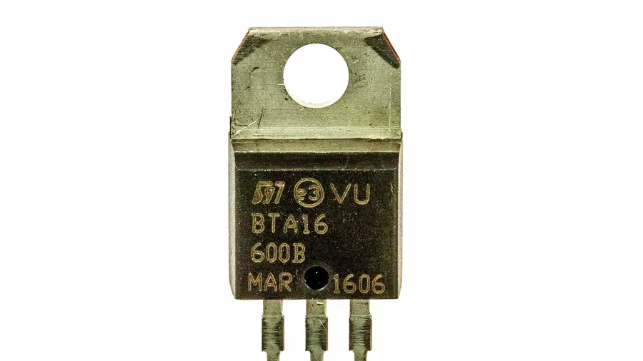
A TRIAC, or Triode for Alternating Current, is a three-terminal semiconductor device engineered to function as a bidirectional switch for AC power control. Its core functionality lies in its ability to conduct current in either direction upon activation, distinguishing it from diodes which only allow unidirectional current flow. This bidirectional conductivity makes TRIACs particularly suitable for AC circuit applications where controlled switching is required.
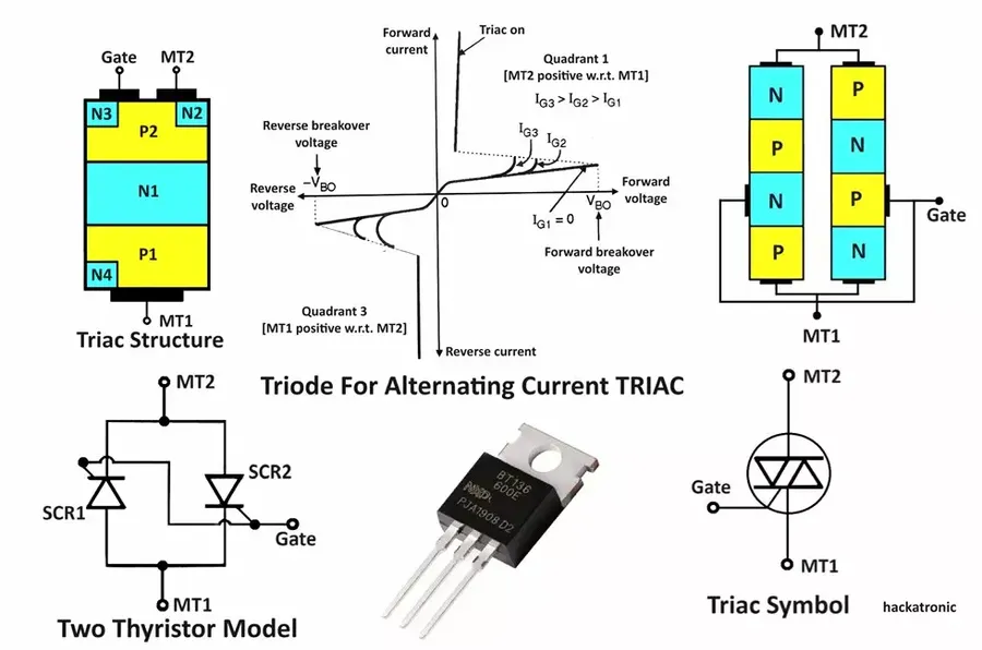
TRIACs, or Triode for Alternating Current, function as bidirectional switches, enabling current flow in either direction within an AC circuit. This behavior is achieved through a sophisticated four-layer semiconductor structure, analogous to two thyristors connected in inverse parallel within the same device, facilitating conduction during both positive and negative alternations of the AC waveform.
Central to the operation of a TRIAC is the gate terminal. Applying a small current to this terminal triggers the TRIAC into a conductive state, allowing current to flow between Main Terminal 1 (MT1) and Main Terminal 2 (MT2), regardless of polarity. Once triggered, the TRIAC remains conductive until the current flowing through the device falls below a certain threshold known as the holding current. This is different from SCR's which once triggered require the current to drop to zero to turn off. The triggering and holding mechanisms are fundamental to a TRIAC's function as an AC switch.
The internal structure of a TRIAC can be visualized as a combination of two SCRs (Silicon Controlled Rectifiers) integrated together. This integration allows the TRIAC to switch current in both directions unlike an SCR which can only switch in one direction. When a positive voltage is applied to the gate with respect to MT1 or a negative voltage with respect to MT2, the device will switch on. Likewise, when a negative voltage is applied to the gate with respect to MT1 or a positive voltage with respect to MT2, the device will also switch on. The minimum gate current to switch the device varies with the voltage difference between MT1 and MT2 and the temperature of the device.
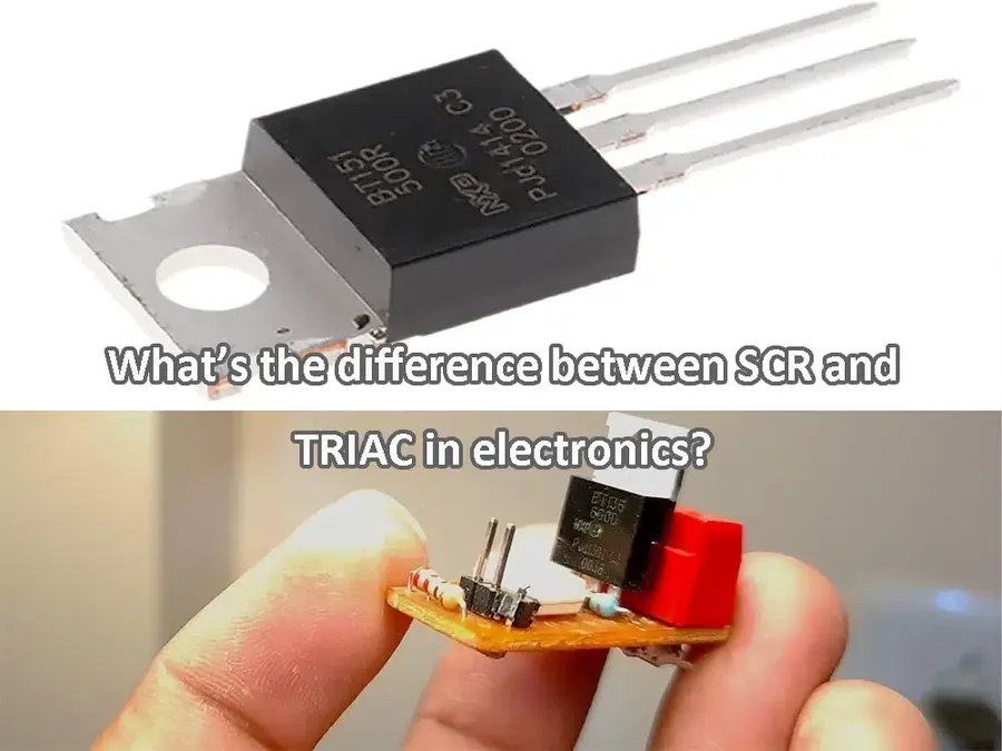
TRIACs and Silicon Controlled Rectifiers (SCRs) are both semiconductor devices used for switching applications, but they exhibit fundamental differences in their conduction behavior. TRIACs are specifically designed for bidirectional AC current control, while SCRs are unidirectional devices typically used in DC circuits or controlled rectification of AC.
| Feature | TRIAC | SCR |
|---|---|---|
| Conduction Direction | Bidirectional (AC) | Unidirectional (DC) |
| Number of Terminals | 3 (MT1, MT2, Gate) | 3 (Anode, Cathode, Gate) |
| Primary Application | AC power control, phase control | Controlled rectification, DC power control |
| Gate Triggering | Can be triggered with either positive or negative gate current | Triggered with positive gate current |
| Holding Current | Maintains conduction until current falls below a minimum level in either direction | Maintains conduction until current falls below a minimum level in forward direction |
| Typical Circuit | AC circuits, light dimmers, motor speed controls | DC circuits, rectifiers, inverters |
The fundamental difference lies in their structure and capability to handle current flow. TRIACs are effectively two SCRs connected in inverse parallel, which allows them to conduct in both directions. This makes them well suited for AC applications. SCRs, on the other hand, have a single p-n junction structure, allowing current to flow only from anode to cathode, making them suitable for unidirectional DC applications or situations where only half the AC cycle needs to be controlled.
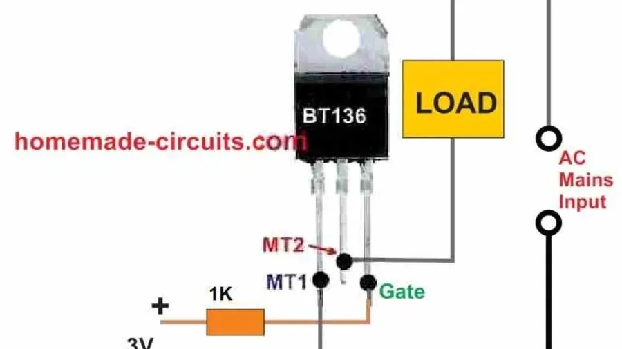
TRIACs, essential components in AC power control, are represented by a specific symbol in circuit diagrams, which facilitates clear communication in technical designs. Identifying the terminals correctly is crucial for proper circuit implementation and functionality. The TRIAC's three terminals—Main Terminal 1 (MT1), Main Terminal 2 (MT2), and Gate (G)—each play a distinct role in its operation.
The schematic symbol for a TRIAC visually conveys its bidirectional capability, and understanding its representation is fundamental to circuit analysis and design involving AC power control.
Understanding the switching characteristics and parameters of TRIACs is crucial for effective circuit design and application. These parameters define the TRIAC's operational limits and influence its behavior in AC power control. Key parameters include gate trigger voltage, holding current, maximum current handling capacity, and the nuances of symmetrical and asymmetrical firing.
| Parameter | Description | Typical Values | Significance |
|---|---|---|---|
| Gate Trigger Voltage (VGT) | The minimum voltage required at the gate terminal to initiate conduction. This voltage is applied between the gate and MT1. | 0.5V to 2V (DC) | Ensures the TRIAC turns ON reliably. It must be considered in gate driver design. |
| Gate Trigger Current (IGT) | The minimum current required at the gate terminal to initiate conduction. | 1mA to 50mA | Along with VGT, this defines the power requirement of gate triggering circuit. |
| Holding Current (IH) | The minimum current required to maintain the TRIAC in the ON state. If the current drops below this, the TRIAC turns OFF. | 5mA to 100mA | Determines the minimum load current required to keep the TRIAC conducting after triggering. |
| Maximum On-State Current (IT(RMS)) | The maximum root mean square (RMS) current that the TRIAC can safely handle in the conducting state. | 1A to 100A+ | Specifies the TRIAC's load-handling capacity; exceeding this can cause damage. |
| Maximum Repetitive Peak Off-State Voltage (VDRM) | The maximum peak voltage that the TRIAC can block in the non-conducting state | 200V to 1200V+ | Defines the maximum reverse voltage the TRIAC can handle. This is critical for selecting a TRIAC for the application. |
| Surge Current (ITSM) | The non-repetitive peak current that the TRIAC can handle for a short duration. | 10A to 1000A+ | Defines the TRIAC capability to handle short duration current surges, which are common in inductive loads. |
| Symmetrical Firing | The TRIAC can be triggered by a positive or negative gate voltage with respect to MT1. | N/A | TRIACs inherently exhibit symmetrical firing, allowing for bidirectional control in AC circuits. |
| Asymmetrical Firing | Some specialized TRIACs are designed with slightly different trigger sensitivities for positive and negative gate voltages | N/A | Used in specialized applications that require precise phase control. |
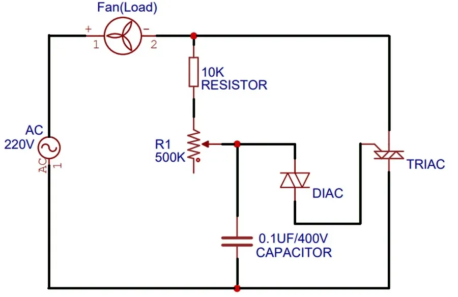
TRIACs, due to their ability to control AC power bidirectionally, are integral components in a multitude of applications across various sectors. These applications range from simple household devices to complex industrial control systems, showcasing the versatility of TRIACs in managing electrical loads.
| Application | Control Method | Benefit | Typical Settings |
|---|---|---|---|
| Light Dimmer | Phase Angle Control | Adjustable Lighting, Energy saving | Residential and commercial lighting. |
| Motor Speed Control | Phase Angle Control, Voltage Adjustment | Precise speed regulation, Energy saving | Fans, pumps, power tools |
| Temperature Control | On/Off Switching, Phase Angle control | Accurate temperature regulation | Heaters, ovens, HVAC |
| Solid State Relays | Switching | Reliable AC switching, long lifetime | Industrial automation, Power control systems |
Designing reliable TRIAC circuits requires careful consideration of several key factors. Proper gate driving, the implementation of snubber circuits, and effective heat dissipation are paramount to prevent device failure and ensure optimal performance in AC power control applications. This section outlines practical tips for robust TRIAC circuit design.
This section addresses common queries regarding TRIACs, clarifying their functionalities and applications in AC power control. Understanding these frequently asked questions will solidify your grasp of TRIAC operation and their suitability for diverse electrical engineering tasks.
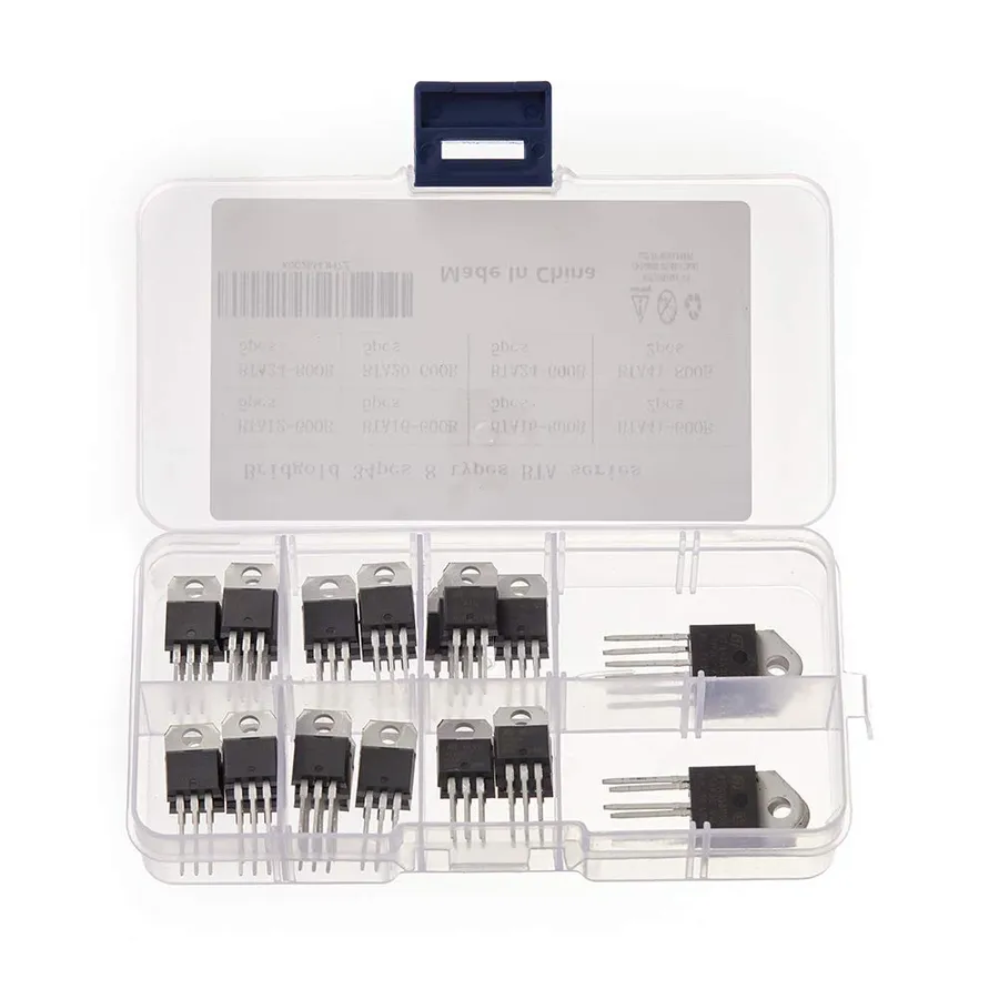
Selecting the appropriate TRIAC for a given application is crucial for ensuring both reliable circuit operation and longevity. This process involves carefully evaluating the circuit requirements and matching them with the TRIAC’s operational specifications. A mismatch can result in device failure, erratic performance, or insufficient control over the load. The key factors to consider when selecting a TRIAC include voltage and current handling capabilities, load characteristics, package type, and specific triggering requirements.
| Parameter | Description | Importance |
|---|---|---|
| Voltage Rating (VDRM, VRRM) | The maximum allowable voltage the TRIAC can withstand in both forward and reverse directions without conducting. It’s specified as repetitive peak off-state voltage. | Must exceed the peak voltage of the AC supply to prevent damage. |
| Current Rating (IT(RMS)) | The maximum RMS current the TRIAC can continuously handle. It's crucial for managing the current requirements of the load. | Must be greater than or equal to the load’s expected current draw to avoid thermal overload and failure. |
| Gate Trigger Current (IGT) | The minimum gate current required to switch the TRIAC into conduction. | Affects the design of the gate drive circuit and the sensitivity of the device. |
| Holding Current (IH) | The minimum current required to maintain the TRIAC in a conducting state. Once the current drops below this value, the device will turn off. | Important to avoid unwanted turn-off of TRIAC, especially with inductive loads |
| Surge Current Rating (ITSM) | The maximum non-repetitive surge current the TRIAC can tolerate. | Must exceed the inrush current associated with the connected load to prevent device degradation. |
| Operating Temperature Range | The range of ambient temperatures within which the TRIAC is designed to operate reliably. | Proper thermal design and heatsinking are required to prevent thermal overload. |
| Package Type | The physical casing of the TRIAC (e.g., TO-220, TO-252, SMD). | Determines the mounting method and thermal characteristics, influencing the overall design and heatsinking needs. |
When choosing a TRIAC, it's essential to consider the load type. Resistive loads, like heaters or incandescent lights, have relatively stable current demands. However, inductive loads, such as motors or transformers, can cause significant inrush currents during turn-on or turn-off events, requiring TRIACs with higher surge current ratings and snubber circuits for proper operation. Additionally, the control circuit must be carefully designed to provide the required gate trigger current (IGT) and to prevent false triggering. Furthermore, ensure that the selected TRIAC matches the specific requirements of the circuit’s application, whether it be phase control, full-wave control, or zero-crossing switching.
Advanced TRIAC control transcends basic on/off switching, delving into sophisticated methods that allow for precise modulation of AC power. These techniques, including phase angle control, zero-crossing detection, and microcontroller-based implementations, enable applications requiring finer control of electrical loads.
The following section will discuss three advanced techniques: phase angle control, zero-crossing detection, and microcontroller-based control.
**Phase Angle Control:** This technique involves triggering the TRIAC at a specific point within the AC waveform, rather than at the zero-crossing point. By delaying the firing angle, the average power delivered to the load can be adjusted. This is crucial for applications like light dimmers and motor speed controls, where a gradual increase or decrease in power is required. The firing angle is typically controlled using a control circuit that is synchronized with the AC line frequency.
**Zero-Crossing Detection:** Zero-crossing detection is a method used to trigger the TRIAC at or near the point where the AC waveform crosses zero volts. This technique minimizes electrical noise and electromagnetic interference (EMI) that can occur when switching at higher voltage points. By switching at zero crossing, the current waveform is more sinusoidal, which can increase component life and reduce stress on both the device and the load. Zero-crossing detection is often used in combination with other control techniques.
**Microcontroller-Based Control:** Microcontrollers allow for sophisticated, adaptive control of TRIACs. Using a microcontroller enables implementation of closed-loop control systems, where the actual output (e.g. temperature or light intensity) is measured and fed back into the control loop to adjust the firing angle. Microcontrollers also facilitate complex control algorithms that can respond to various inputs to achieve desired system operation. This is particularly beneficial for applications requiring precise and dynamic control of AC power.
TRIACs are truly the unsung heroes of AC power control, enabling seamless operation of countless devices around us. From dimming the lights to powering large motors, these versatile semiconductors are fundamental in electronics. Understanding how TRIACs function, their advantages, and proper application methods unlocks the potential for more sophisticated and efficient control over electrical systems. As technology continues to evolve, TRIACs will surely remain a key component in many areas of electrical engineering, particularly where precise AC control is required, thus underscoring the importance of understanding the power of TRIACs.

