Understanding the Diode Bridge Rectifier: From AC to DC Power
2025.01.18
In our modern world, electronic devices are powered by direct current (DC), yet most of our electricity comes as alternating current (AC). Enter the unsung hero: the diode bridge rectifier. This clever arrangement of diodes, like the silent traffic controllers of electricity, transforms AC into the stable DC that powers everything from your smartphone to your refrigerator. This article will dissect the diode bridge rectifier, providing a thorough explanation of its operation, various applications, and a practical understanding of its importance in our technology driven lives.
What is a Diode Bridge Rectifier?
Diode Bridge Rectifier Component
A diode bridge rectifier is an essential electronic circuit utilizing four diodes in a bridge configuration to efficiently convert alternating current (AC) into direct current (DC). This fundamental component is ubiquitous in power supplies and various electronic devices, providing a stable DC output from an AC source.
How the Diode Bridge Rectifier Works: A Step-by-Step Explanation
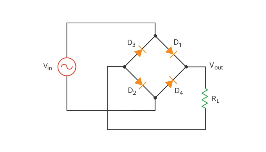
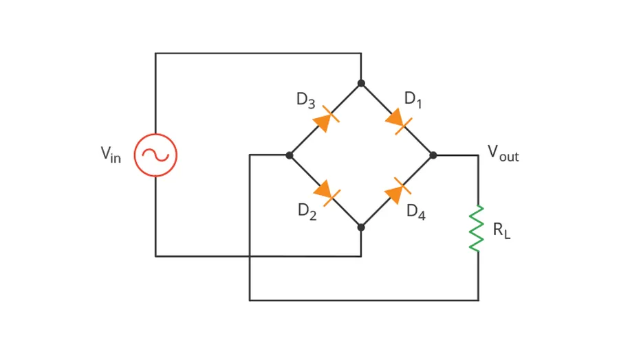
Diode Bridge Rectifier Circuit
The diode bridge rectifier efficiently converts alternating current (AC) to pulsating direct current (DC) through a carefully orchestrated sequence of diode conduction during alternating AC cycles. This conversion relies on the unidirectional conduction property of diodes.
Here's a breakdown of the operational steps:
Positive Half-Cycle of AC Input When the AC input voltage is positive, current flows from the positive terminal of the AC source, through diode D1, then through the load, and returns through diode D3 to the negative terminal of the AC source. Diodes D2 and D4 are reverse-biased and do not conduct during this half-cycle. The load receives a current pulse with the voltage polarity consistent with direct current.
Negative Half-Cycle of AC Input When the AC input voltage switches to negative, current now flows from the negative terminal of the AC source, through diode D2, then through the same load (in the same direction as before), and returns through diode D4 to the positive terminal of the AC source. Diodes D1 and D3 are reverse-biased and do not conduct during this half-cycle. Again, the load receives a current pulse with the same DC voltage polarity as before.
Pulsating DC Output The output across the load consists of successive half-cycles of the input AC voltage, all with the same polarity, resulting in pulsating DC. This pulsating DC can then be smoothed out by filtering circuits, typically using capacitors, to obtain a relatively constant DC voltage.
The key is that regardless of the polarity of the AC input, current flows through the load in the same direction due to the bridge configuration, ensuring full-wave rectification. This process effectively utilizes both the positive and negative half-cycles of the AC input to produce DC output.
Full-Wave Rectification vs. Half-Wave Rectification
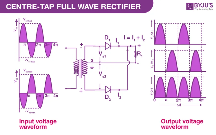
Waveform Comparison
The diode bridge rectifier enables full-wave rectification, a significant improvement over half-wave rectification. Full-wave rectification utilizes both halves of the AC input cycle to produce a DC output, resulting in higher efficiency and a smoother DC output with less ripple.
Feature
Full-Wave Rectification (Diode Bridge)
Half-Wave Rectification
Diodes Used
4
1
AC Cycle Utilization
Both Positive and Negative
Only Positive or Negative
DC Output
Pulsating DC with lower ripple
Pulsating DC with higher ripple
Efficiency
Higher (~81.2%)
Lower (~40.6%)
Transformer Usage
Center-tapped transformer not needed (standard transformer OK)
Typically uses a standard or center-tapped transformer
Output Frequency
Twice the AC input frequency
Same as the AC input frequency
The key advantage of full-wave rectification, achieved through a diode bridge, lies in its ability to convert more of the AC power into usable DC power. This is reflected in its efficiency. In contrast, half-wave rectification discards half of the AC input, leading to lower efficiency and a more irregular DC output requiring heavier filtering.
Key Components: The Role of Each Diode in the Bridge
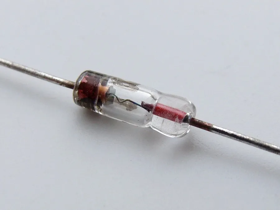
Electronic Diodes
Within a diode bridge rectifier, each of the four diodes plays a crucial and distinct role in converting alternating current (AC) to direct current (DC). These roles can be analyzed by understanding how current flows through the circuit during both the positive and negative half-cycles of the AC input. Each diode is strategically placed to facilitate current flow in only one direction, thereby ensuring that the output current is always unidirectional.
The diodes are typically labeled D1, D2, D3, and D4, and they are arranged in a closed-loop configuration resembling a bridge. The AC input is applied to two opposite corners of this bridge, while the DC output is taken from the other two corners. During the positive half-cycle of the AC input, current flows through two diodes; during the negative half-cycle, it flows through the other two, all while ensuring the current flow at the output is in the same direction. This alternating conduction by the diodes ensures that both halves of the AC waveform contribute to the DC output.
Diode
Function During Positive Half Cycle
Function During Negative Half Cycle
D1
Conducts current, allowing it to flow to the positive DC output
Does not conduct (Reverse biased)
D2
Does not conduct (Reverse biased)
Conducts current, allowing it to flow to the positive DC output
D3
Does not conduct (Reverse biased)
Conducts current, allowing it to flow to the negative DC output
D4
Conducts current, allowing it to flow to the negative DC output
Does not conduct (Reverse biased)
In summary, D1 and D4 conduct together during one half-cycle, while D2 and D3 conduct during the other. This push-pull action of the diodes ensures that the load receives current during both halves of the AC input, converting it to a pulsating DC output. By doing so, they rectify the alternating current into a form of DC that while still rippling, is suitable for further regulation in most electronic power supplies.
Advantages of Using a Diode Bridge Rectifier
Power Adapter Components
Diode bridge rectifiers offer significant advantages over other rectification methods, primarily due to their ability to perform full-wave rectification, which results in a more efficient and smoother DC output. These benefits contribute to their widespread use in various electronic applications.
High Efficiency By utilizing all portions of the AC waveform, bridge rectifiers achieve higher efficiency than half-wave rectifiers, converting a larger amount of AC power into usable DC power. This improved efficiency directly translates to reduced energy waste and less heat generation, improving overall system performance.
Improved DC Output The full-wave rectification process yields a DC output with a lower ripple factor, meaning the voltage is more consistent, less pulsed, and smoother than that produced by half-wave rectifiers. This reduces the need for additional filtering circuitry, saving costs and component space.
Full-Wave Rectification The primary function of a diode bridge is full-wave rectification, converting both positive and negative halves of the AC cycle into a single polarity DC output. This characteristic ensures no energy is wasted, providing the most effective AC-to-DC power conversion.
Compact Size Despite comprising four diodes, bridge rectifiers can be implemented in relatively small form factors. Integrated bridge rectifier packages are readily available, making it convenient to implement on circuit boards. This is advantageous where space is a constraint.
Reliability Bridge rectifiers have a robust and simple design, making them highly reliable. The well-understood operation of diodes and the clear current paths in bridge rectifiers contribute to their longevity and consistent performance, minimizing failure rates.
Feature
Half-Wave Rectifier
Full-Wave (Bridge) Rectifier
Efficiency
Lower
Higher
DC Output Quality
Higher Ripple, Pulsating
Lower Ripple, Smoother
Utilization of AC Wave
Utilizes only half of the AC wave
Utilizes both halves of the AC wave
Number of Diodes
1
4
Complexity
Simpler
Slightly More Complex
Cost
Generally Cheaper
Slightly More Expensive
Diode Bridge Rectifier Applications in Real-World Electronics
Electronic Circuit Board
Diode bridge rectifiers are ubiquitous in modern electronics due to their efficiency and reliability in converting AC power to DC power. These circuits are fundamental components in a vast array of devices, ranging from everyday consumer products to sophisticated industrial and renewable energy systems.
Consumer Electronics Power Supplies Virtually all electronic devices that operate on DC power but are plugged into an AC wall outlet utilize a diode bridge rectifier. This includes chargers for smartphones, laptops, and tablets, as well as power adapters for various electronic gadgets. The rectifier is crucial for converting the AC from the mains to a stable DC supply required by the device's internal circuits.
Industrial Equipment In industrial settings, diode bridge rectifiers are essential in power supplies for motor drives, automated machinery, and control systems. They provide the necessary DC power to operate these systems reliably and efficiently. Heavy-duty rectifiers are often used in these applications to handle higher voltage and current demands.
Automotive Systems Automotive electrical systems utilize diode bridge rectifiers as part of the alternator circuit. The alternator generates AC power that needs to be converted to DC to charge the car's battery and operate the various electrical systems within the vehicle. The robustness of diode bridge rectifiers makes them ideal for the harsh environment within an automobile.
Renewable Energy Systems In solar photovoltaic (PV) systems, diode bridge rectifiers play a vital role in converting the AC output of inverters to DC for battery charging and storage. Similarly, they can also be found in wind power systems, converting AC from wind turbines into DC for grid connection and energy storage. These applications highlight the importance of diode bridge rectifiers in facilitating the transition to renewable energy.
Welding Machines Many welding machines, especially those that use DC output, rely on diode bridge rectifiers to convert the incoming AC power into the DC current needed for the welding process. The rectifiers in welding equipment need to be robust to handle the high currents and voltage demands.
LED Lighting LED (light emitting diode) lighting systems, particularly those powered directly from the AC mains, use bridge rectifiers to create the DC voltage needed to drive the LEDs. This is a crucial step to ensure LEDs operate correctly and safely as they require DC current.
Choosing the Right Diode Bridge Rectifier: Key Parameters
Selecting the correct diode bridge rectifier is crucial for the reliable and efficient operation of any electronic circuit. The selection process involves careful consideration of several key parameters that must match or exceed the demands of the application. These parameters primarily include voltage ratings, current ratings, temperature specifications, and physical packaging. Ignoring these parameters can lead to component failure, inefficient operation, or even safety hazards. Therefore, a detailed understanding of these considerations is essential for design engineers and hobbyists alike.
Parameter
Description
Importance
Maximum Average Forward Current (IF(AV))
The maximum average current the rectifier can safely handle. Specified in Amperes.
Critical to avoid overheating and component failure. Must exceed the expected load current.
Peak Repetitive Reverse Voltage (VRRM)
The maximum reverse voltage the rectifier can withstand without breakdown. Specified in Volts.
Must be higher than the peak AC voltage applied to the rectifier. Prevents reverse conduction and potential damage.
Forward Voltage Drop (VF)
The voltage drop across the diode when it is conducting. Specified in Volts.
Affects efficiency; Lower VF means less power loss as heat. Crucial for high-power applications.
Operating Temperature Range
The range of temperatures within which the rectifier is designed to operate. Specified in degrees Celsius.
Ensures the rectifier functions reliably under various ambient conditions. Failure to operate within specified limits can cause damage.
Physical Packaging
The physical form of the rectifier, including the number of pins, mounting style, and material.
Must match the design of the circuit board for proper integration. Options include through-hole, surface mount, and chassis mount.
Surge Current Rating (IFSM)
The maximum non-repetitive forward current the diode can withstand for a short period. Specified in Amperes.
Important for protecting the rectifier during power-up or transient events. It must be much higher than the expected inrush current.
Frequently Asked Questions About Diode Bridge Rectifiers
This section addresses common queries regarding diode bridge rectifiers, providing clear and concise answers to help deepen understanding of their function, design, and application.
What is the primary function of a diode bridge rectifier? The primary function of a diode bridge rectifier is to convert alternating current (AC) into direct current (DC). This conversion is essential for powering most electronic devices, which operate on DC power.
Why are four diodes used in a bridge rectifier circuit? Four diodes are used in a bridge rectifier to facilitate full-wave rectification. This arrangement allows the circuit to utilize both the positive and negative halves of the AC input, resulting in a more efficient conversion to DC than half-wave rectification. Two diodes conduct during the positive cycle, and the other two conduct during the negative cycle.
How can I identify a malfunctioning diode bridge rectifier? A faulty bridge rectifier may exhibit several symptoms, including a complete lack of DC output, an output significantly lower than expected, or excessive ripple in the DC output. Individual diodes within the bridge can fail, resulting in these issues. Testing each diode using a multimeter set to the diode test mode is recommended to pinpoint the failed component.
What are the advantages of using a bridge rectifier over a half-wave rectifier? Compared to half-wave rectifiers, bridge rectifiers offer several advantages. They provide full-wave rectification, leading to higher efficiency, a higher DC output voltage, and reduced ripple. Additionally, the full-wave rectification process ensures that both halves of the AC cycle are utilized, resulting in better power utilization.
Can a diode bridge rectifier handle both small and large power applications? Yes, diode bridge rectifiers are scalable and used in a wide range of power applications. Small signal rectifiers are used for signal processing, while larger power rectifiers are found in power supplies and industrial equipment. The choice of rectifier is based on the required current and voltage ratings of the application.
What is the 'forward voltage drop' associated with a diode bridge rectifier and why is it important? The forward voltage drop is the voltage drop across a diode when it's conducting in the forward direction. In a bridge rectifier, there are always two diodes conducting at any given time. Therefore, the total voltage drop of approximately 2 times the forward voltage of each diode must be considered. This voltage drop reduces the overall efficiency and the amount of DC output voltage.
Are bridge rectifiers used in both linear and switching power supplies? Yes, bridge rectifiers are a fundamental component in both linear and switching power supplies. In linear power supplies, they convert AC to a pulsating DC, which is then filtered and regulated. In switching power supplies, they serve as the initial AC to DC conversion stage before further conversion is done.
Troubleshooting Common Diode Bridge Rectifier Issues
Effective troubleshooting of diode bridge rectifiers is essential to maintain the integrity of power conversion circuits. This section outlines common issues, their diagnostic procedures, and remedial actions to ensure reliable system operation.
Blown Diodes One or more diodes within the bridge may fail due to overcurrent or voltage spikes. The primary symptom is a complete or partial loss of rectification, leading to a significant decrease or absence of DC output. This can be confirmed by testing each diode individually with a multimeter set to diode check mode; a reading indicating both low forward and reverse resistance implies the diode is shorted, while infinite resistance in both directions means it is open. Replacement of the faulty diode(s) is the necessary action.
Under-performing Rectification Reduced or inconsistent DC output may suggest that one or more diodes are functioning suboptimally without a complete failure, usually observed through a reduction in output voltage and an increase in ripple. The condition can be attributed to heat damage and can be confirmed by comparing the forward voltage drop of each diode under similar operational conditions. If one or more diodes display significantly higher voltage drops than others, replacement of the degraded diodes is the suggested remedy.
Excessive Heat Generation High operating temperatures of the rectifier components, including the diodes themselves, indicates excessive current or inefficient operation. Heat generation can lead to premature failure. Check the current load compared to the specifications of the diodes being used and ensure adequate heat dissipation is in place such as a heat sink, or by derating the components for high ambient operating temperatures. If the current load exceeds the ratings, or heat dissipation is insufficient, this must be rectified
Input Voltage Issues Ensure that the AC input voltage is within the specified range of the rectifier, as over-voltage can lead to immediate failure and under voltage might lead to an inadequate DC output or an inability to conduct properly during positive or negative cycles. Use a voltmeter to verify the input voltage and make corrections by adjusting transformer configurations or by providing appropriate input voltage sources.
Output Ripple A higher than expected ripple in the DC output may indicate a failure of the diodes or the filter capacitors (if used) after the rectifier. If you have ripple in the output, confirm the condition of all diodes and if there is no change, proceed with inspecting other components such as the filter capacitors.
Intermittent Operation Inconsistent operation of the rectifier can be caused by loose connections, intermittent failures of diodes, or thermal issues. Verify the quality of solder joints and all physical connections. If the problem persists, perform detailed testing of the diodes individually, and use freeze spray or gentle heating to isolate any temperature-related intermittent issues.
The diode bridge rectifier is a pivotal element in converting AC to DC, powering countless devices around us. Its clever arrangement of diodes ensures a consistent DC output, vital for the reliable operation of electronic circuits. By understanding its working principle, advantages, and real-world applications, we not only grasp a fundamental concept of electrical engineering but also gain a greater appreciation for the technology that shapes our daily lives. From the smallest USB adapter to the most advanced industrial machinery, the reliable diode bridge rectifier is there, silently ensuring that AC power is converted to the steady DC power we need. As we move towards more efficient and compact electronic devices, the crucial role of the diode bridge rectifier will only continue to grow.