In the realm of semiconductor devices, the unijunction transistor (UJT) stands out for its unique ability to act as an electrically controlled switch. Unlike its more common cousins, the bipolar junction transistor (BJT) and field-effect transistor (FET), the UJT boasts a single junction and peculiar characteristics that make it indispensable in various timing and triggering circuits. This article will guide you through the intricacies of the UJT, exploring its structure, function, applications, and more, offering an illuminating glimpse into this essential component.
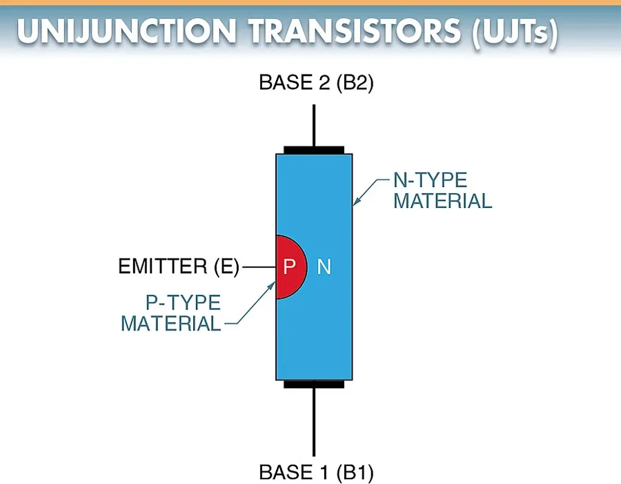
The unijunction transistor (UJT) is a three-terminal semiconductor device distinguished by its unique structure and electrical characteristics. Unlike conventional bipolar junction transistors (BJTs), which have two junctions, the UJT features a single p-n junction, giving rise to its name. This singular junction is pivotal to its operation and is the source of its distinctive behavior.
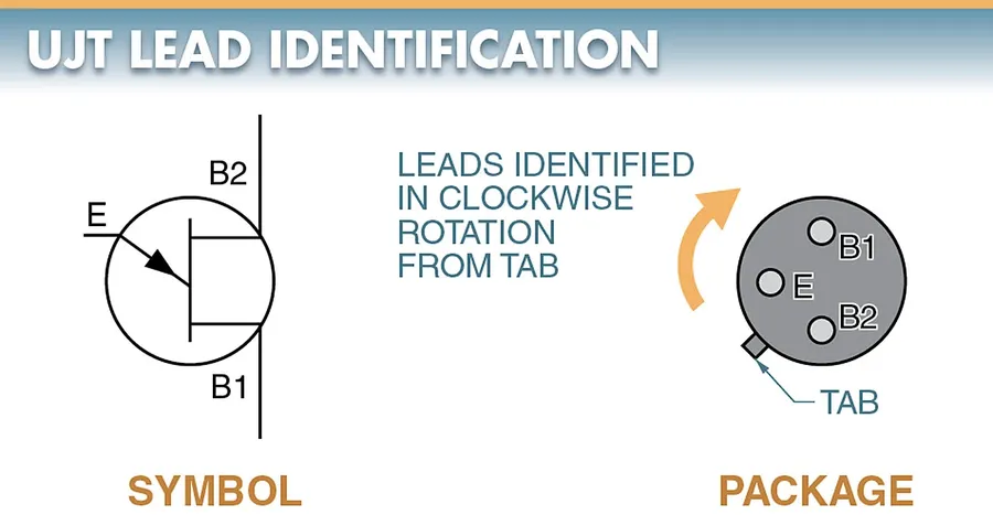
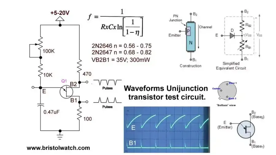
The UJT comprises a lightly doped n-type silicon bar with a small, heavily doped p-type region alloyed into it, creating a single p-n junction. This structure gives rise to three terminals: the emitter (E), which is connected to the p-type region, and two bases, Base 1 (B1) and Base 2 (B2), which are ohmic contacts at either end of the n-type silicon bar. Understanding the physical arrangement of these elements is crucial to grasping the device's functionality.
| Feature | Unijunction Transistor (UJT) | Bipolar Junction Transistor (BJT) |
|---|---|---|
| Number of P-N Junctions | 1 | 2 |
| Number of Terminals | 3 (Emitter, Base 1, Base 2) | 3 (Collector, Base, Emitter) |
| Primary Function | Switching, Relaxation Oscillator | Amplification, Switching |
| Structure | N-type bar with a P-type region | NPN or PNP sandwich structure |
The unijunction transistor (UJT) operates based on a unique mechanism characterized by a negative resistance region, which is crucial for its applications, especially in relaxation oscillators. This behavior is governed by the device's internal structure and the interplay of voltage and current within its layers, which is distinct from standard bipolar junction transistors (BJTs).
Central to UJT operation is the intrinsic standoff ratio (η), a critical parameter that dictates the firing voltage, also known as the peak point voltage (Vp), at which the device switches from its off state to its conducting state. The UJT’s emitter-base junction exhibits a non-linear behavior where an increase in emitter voltage beyond Vp leads to a reduction in emitter resistance, demonstrating the aforementioned negative resistance characteristic.
The UJT's operation cycle begins with the emitter junction reverse biased, essentially acting as an open switch. When the voltage at the emitter reaches the peak point voltage (Vp), the emitter junction becomes forward biased due to conductivity modulation of the silicon bar, injecting current into the base region. This transition causes the UJT to enter a conductive state until the emitter current drops below the valley current, at which point it returns to its high-resistance state. This cyclic behavior is what makes the UJT suitable for relaxation oscillators and triggering mechanisms.
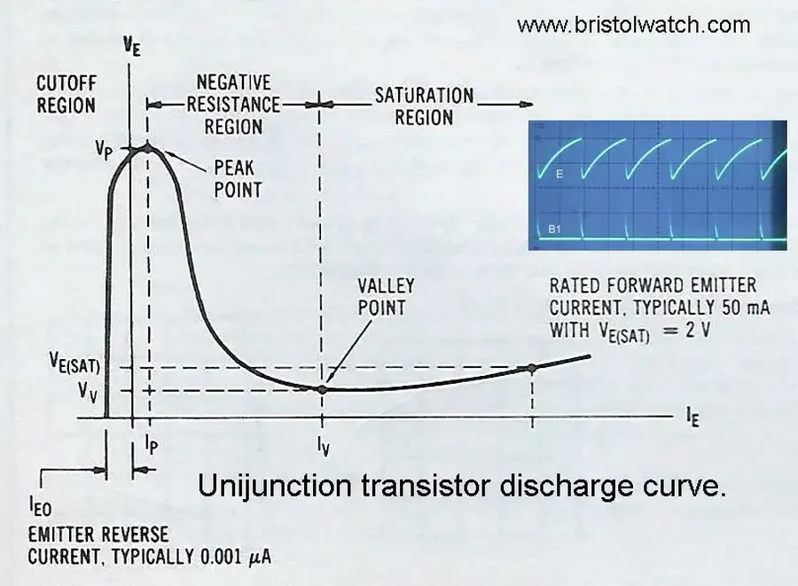
The performance of a Unijunction Transistor (UJT) is dictated by several key parameters, notably the peak point voltage (Vp), valley point voltage (Vv), and interbase resistance (Rbb). These parameters define the UJT's unique negative resistance region, which is crucial for its applications.
| Parameter | Symbol | Description | Impact on Circuit Performance |
|---|---|---|---|
| Peak Point Voltage | Vp | The emitter voltage at which the UJT switches from the off-state to the conducting state. | Determines the trigger point for UJT based oscillator and switching circuits. |
| Valley Point Voltage | Vv | The emitter voltage below which the UJT returns to the non-conducting state. | Influences the stability and frequency of UJT oscillator circuits. |
| Interbase Resistance | Rbb | The resistance between base 1 and base 2 when the emitter is open. | Affects the intrinsic standoff ratio (η) and, therefore, Vp. |
| Intrinsic Standoff Ratio | η | A parameter determined by Rbb and the resistance of the P-type emitter, which is crucial in calculating Vp, where Vp = ηVbb + Vd. | Defines the voltage division between the interbase resistance and the emitter-base diode, critical for calculating the peak voltage Vp. |
| Emitter Saturation Current | Ie(sat) | The current that flows from the emitter when it's saturated. | This parameter is important when considering high current applications. |
These parameters are interrelated and vary from one UJT model to another, however understanding these will help in effective circuit design. Notably, The peak point voltage (Vp) is calculated using the formula Vp = ηVbb + Vd, where Vbb is the voltage between the two bases and Vd is the voltage drop across the emitter diode. The intrinsic standoff ratio (η) is a crucial parameter that is defined as η=R1 / (R1+R2), which are effectively two internal resistances of UJT. The voltage across the UJT emitter needs to reach Vp for it to transition from OFF state to ON state.
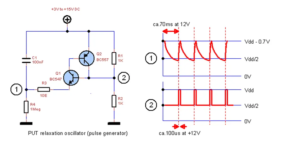
The unijunction transistor (UJT) finds a primary application in relaxation oscillator circuits, leveraging its unique negative resistance characteristic to generate timing pulses. These oscillators are fundamental in many electronic systems where a simple and reliable timing circuit is needed.
The functionality of a UJT relaxation oscillator relies on the repetitive charging and discharging of a capacitor, controlled by the UJT's inherent properties. The core of this functionality resides in the UJT's capacity to switch between high and low resistance states based on the voltage at its emitter terminal, making it a natural fit for such circuits.
The operation can be described as follows: Initially, the capacitor charges through a resistor until the emitter voltage reaches the UJT’s peak point voltage (Vp). At this point, the UJT switches to its low-resistance state, allowing the capacitor to discharge rapidly through the emitter to base 1. Once the discharge is complete and the emitter voltage falls below the valley point voltage (Vv), the UJT reverts to its high resistance state and the capacitor begins to recharge, continuing the cycle, thus creating a pulsed output.
The frequency of oscillation for a UJT relaxation oscillator can be approximated using the following formula:
f ≈ 1 / (R * C * ln(1 / (1 - η)))
Where:
This formula provides a practical means of calculating the expected oscillation frequency based on the chosen components and intrinsic device characteristics. It also explains why UJTs are ideal for this type of circuit, as the oscillation is determined by passive components, a very stable and predictable method.
While the unijunction transistor (UJT) is most recognized for its role in relaxation oscillators, its unique characteristics make it suitable for other specialized applications, particularly in triggering circuits for power control and timing. These applications leverage the UJT’s ability to rapidly switch from a high-resistance to a low-resistance state when the emitter voltage reaches a specific threshold.
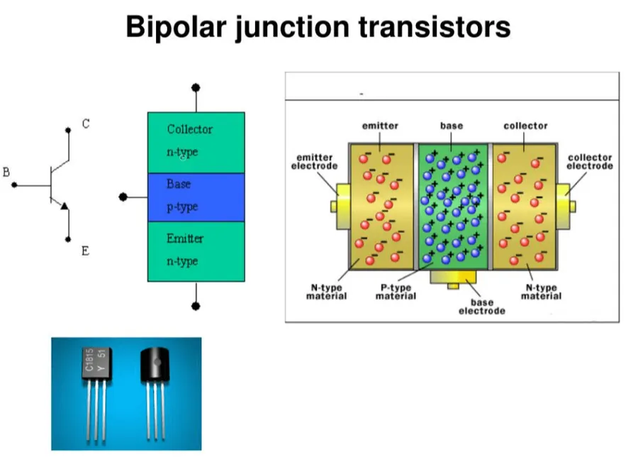
While both unijunction transistors (UJTs) and bipolar junction transistors (BJTs) are semiconductor devices used in electronic circuits, they differ fundamentally in their structure, operating principles, and typical applications. UJTs are primarily used for their unique negative resistance characteristic and ability to function as relaxation oscillators, while BJTs are more general-purpose devices used for amplification and switching.
| Feature | Unijunction Transistor (UJT) | Bipolar Junction Transistor (BJT) |
|---|---|---|
| Structure | Three terminals: emitter (E), base 1 (B1), and base 2 (B2). Single PN junction. | Three terminals: collector (C), base (B), and emitter (E). Two PN junctions. |
| Operating Principle | Negative resistance characteristic. Triggered by emitter voltage reaching a certain fraction of interbase voltage. | Current-controlled device. Current at the base controls the current flow between the collector and emitter. |
| Typical Operation | Operates as a voltage-controlled switch, primarily used in oscillator circuits. | Operates as a current-controlled device, used for amplification and switching. |
| Key Characteristics | Intrinsic standoff ratio (η), peak point voltage (Vp), valley point voltage (Vv). | Current gain (β or hFE), collector-emitter voltage (VCE), base-emitter voltage (VBE). |
| Application Scenarios | Relaxation oscillators, triggering circuits for SCRs, timing circuits. | Amplifiers, digital logic circuits, power switches. |
| Negative Resistance | Exhibits negative resistance region in its characteristic curve, crucial for oscillator applications. | Does not exhibit negative resistance characteristics. |
| Controlling Parameter | Primarily controlled by the voltage at the emitter terminal, in relation to base voltages. | Primarily controlled by the current at the base terminal. |
This section addresses common questions about unijunction transistors (UJTs), providing clear answers regarding their function, operational theory, and applications, particularly their use in relaxation oscillators. We aim to clarify the core concepts related to UJTs for a comprehensive understanding.
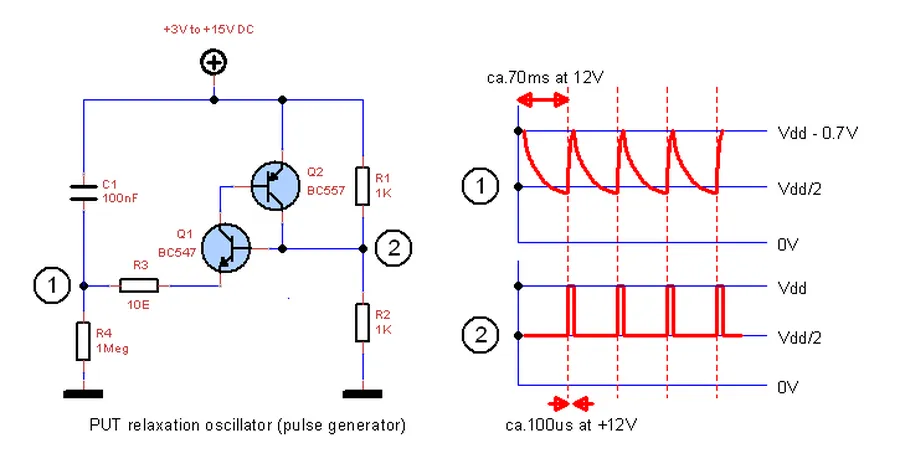
Programmable Unijunction Transistors (PUTs) represent an evolution of the standard UJT, offering greater flexibility in circuit design through adjustable characteristics. Unlike fixed-parameter UJTs, PUTs allow for the manipulation of their firing voltage, making them suitable for more sophisticated applications, particularly in timing and control circuits.
Key to the operation of a PUT is its four-layer structure, which more closely resembles a thyristor rather than a traditional transistor. The PUT's anode, cathode, and gate terminals allow for precise control over the device's triggering threshold. This control is achieved using external resistors, which set the gate voltage and, consequently, the firing voltage required to activate the device.
The fundamental principle governing PUT operation is based on a regenerative process. When the anode voltage exceeds the gate voltage by a specific threshold, the PUT switches rapidly from a non-conducting to a conducting state. This sharp transition, and the ability to program this transition, is what distinguishes PUTs from UJTs.
| Feature | Unijunction Transistor (UJT) | Programmable Unijunction Transistor (PUT) |
|---|---|---|
| Structure | Three-terminal device (Emitter, Base1, Base2) | Four-layer device (Anode, Cathode, Gate) |
| Triggering | Fixed interbase resistance and intrinsic standoff ratio | Programmable firing voltage via external resistors |
| Control | Limited control over characteristics | Greater control over firing voltage and other parameters |
| Relationship to other devices | Similar to a diode with a trigger terminal | Structurally similar to SCRs (Silicon-Controlled Rectifiers) |
| Primary Application | Relaxation oscillators | Precise timing circuits, SCR triggering, voltage sensing |
Moreover, PUTs exhibit strong similarities to Silicon-Controlled Rectifiers (SCRs) in terms of their operational characteristics. Both devices are members of the thyristor family and share a regenerative switching mechanism. In many applications, PUTs are used to trigger SCRs, leveraging the PUT's precise switching behavior to control the SCRs conduction.
In summary, Programmable Unijunction Transistors provide a more versatile and customizable solution compared to traditional UJTs. Their ability to have their characteristics programmed, through the use of external resistors, makes them useful for a wider range of control and triggering applications, and are closely related to the operational characteristics of devices such as SCRs.
Successfully integrating unijunction transistors (UJTs) into circuit designs hinges on understanding their unique characteristics and selecting appropriate components. This section provides practical guidance on UJT selection, design considerations, and troubleshooting techniques to optimize circuit performance and reliability.
The unijunction transistor, despite its singular junction, plays a crucial role in electronics, particularly in applications requiring reliable timing and triggering mechanisms. From simple relaxation oscillators to complex thyristor control circuits, the UJT's unique negative resistance characteristic makes it an indispensable tool. Understanding the principles behind the unijunction transistor not only enhances your knowledge of semiconductor physics but also empowers you to innovate in the design of electronic devices, from basic circuits to more complex systems. The future might see even wider applications of UJTs in niche areas where precise pulse generation and control is needed.

