Capacitors are fundamental to electrical circuits, analogous to tiny rechargeable batteries, but with unique charging and discharging characteristics. From powering our smartphones to stabilizing power grids, capacitor circuits play a crucial role in modern electronics. This article delves into the world of capacitor circuits, exploring their function, diverse types, and practical applications. Understanding these circuits provides insights into the very pulse of our devices.
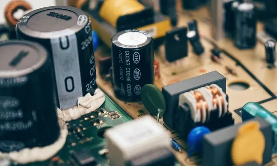
Capacitors, fundamental passive electronic components with two terminals, are essential for energy storage within an electric field. Their primary function in electronic circuits revolves around their ability to shape current flow and manage voltage fluctuations. This behavior makes them indispensable for a wide range of applications.
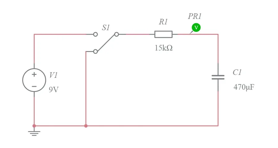
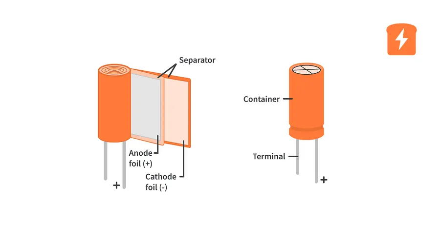
Capacitors store electrical energy by accumulating charge on two conductive plates separated by a dielectric material, the insulator. This energy storage is analogous to a temporary reservoir of electrons. The process of charging involves the movement of electrons to one plate, creating a negative charge, while electrons are depleted from the other plate, creating a positive charge. This charge separation establishes an electric field within the dielectric, which represents the stored energy. When a capacitor discharges, the electrons move back, releasing the stored energy from the electric field.
The ability of a capacitor to store energy is quantified by its capacitance, measured in Farads (F). A capacitor’s energy storage capacity is directly proportional to its capacitance and the square of the voltage applied, as indicated by the equation: E = 1/2CV^2, where E is energy, C is capacitance, and V is voltage. This illustrates that higher capacitance and higher voltage across the capacitor correspond to higher energy storage capability.
| Process | Description | Energy State |
|---|---|---|
| Charging | Electrons move to one plate, depleted from the other | Energy stored as an electric field in the dielectric |
| Discharging | Electrons move from the negatively charged plate to the positively charged plate | Stored energy released as electrons move through a circuit |
The speed at which a capacitor can charge or discharge is affected by the circuit's resistance and capacitance values. In a circuit with low resistance and a high capacitance, the charging and discharging will occur rapidly. The rapid release of energy is what allows capacitors to perform a variety of functions such as filtering, signal coupling and timing in circuits.
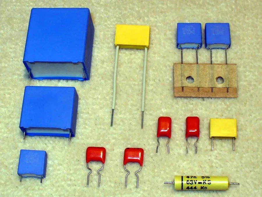
Capacitors are characterized by three primary parameters: capacitance, voltage rating, and tolerance. These parameters are critical for selecting the appropriate capacitor for a given application and ensuring the reliable operation of electronic circuits. Understanding these characteristics is essential for circuit design and analysis.
| Characteristic | Description | Unit | Importance |
|---|---|---|---|
| Capacitance (C) | The ability of a capacitor to store electrical charge. It is directly related to the amount of charge stored per unit of applied voltage. | Farad (F) | Determines the amount of energy a capacitor can store at a given voltage, crucial for timing, filtering, and energy storage applications. |
| Voltage Rating (V) | The maximum voltage that can be safely applied across the capacitor without risking damage or failure to the dielectric. Exceeding this can lead to breakdown and capacitor failure. | Volt (V) | Guarantees safe operation and prevents dielectric breakdown. Selecting a capacitor with a voltage rating exceeding the operating voltage is crucial. |
| Tolerance | The permissible deviation of the actual capacitance value from its nominal (specified) value. It is usually expressed as a percentage. | Percentage (%) | Accounts for manufacturing variability. Affects accuracy in applications like timing and filtering. Capacitors with tighter tolerance result in more reliable and consistent circuit behavior. |
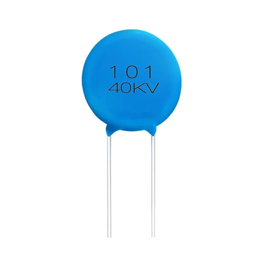
Capacitors are not monolithic; they are manufactured with different materials and construction techniques, resulting in distinct types each suited for specific applications. The selection of a capacitor type is dependent upon the circuit requirements, which includes voltage rating, capacitance value, stability, temperature performance, and the desired lifespan of the circuit. Understanding these diverse types is crucial for effective circuit design.
| Capacitor Type | Dielectric Material | Capacitance Range | Voltage Rating | Typical Applications | Advantages | Disadvantages |
|---|---|---|---|---|---|---|
| Ceramic | Various ceramics (e.g., barium titanate) | 1 pF to 10 µF | Few volts to several kV | Bypass, coupling, and filtering in general electronics | Low cost, small size, good temperature stability for some types | Capacitance varies with temperature and voltage; can exhibit piezoelectric effect |
| Electrolytic (Aluminum) | Aluminum oxide | 0.1 µF to thousands of µF | Few volts to several hundred volts | Power supplies, smoothing, and energy storage | High capacitance in small size, polarized | Limited lifespan, high ESR, prone to leakage, polarity sensitive |
| Electrolytic (Tantalum) | Tantalum pentoxide | 0.1 µF to hundreds of µF | Few volts to several hundred volts | Mobile devices, decoupling, bypass | Compact, good stability, reliable | Expensive, sensitive to reverse polarity and overvoltage, lower maximum voltage |
| Film | Plastic films (e.g., polyester, polypropylene) | 100 pF to 100 µF | Few volts to several kV | Audio circuits, high-frequency applications | Low loss, good stability, high precision | Larger size than ceramic or electrolytic, higher cost |
Capacitors are indispensable components in electronic circuits, serving critical functions such as AC coupling, DC blocking, power supply filtering, and timing. Their ability to store and release energy makes them vital for shaping signal behavior across a wide range of applications, from audio circuits to sophisticated power systems. Specifically, their frequency-dependent impedance allows for precise manipulation of signals based on their frequency content.
| Application | Function | Mechanism | Example |
|---|---|---|---|
| AC Coupling | Passing AC signals while blocking DC components. | Capacitor's impedance is low for AC, high for DC. | Audio amplifier input stage to remove DC bias. |
| DC Blocking | Preventing DC current flow in a circuit while allowing AC to pass. | Capacitor's impedance is high for DC, low for AC. | Isolating one stage of a circuit from the DC bias of the following stage. |
| Power Supply Filtering | Reducing ripple voltage in a power supply. | Capacitors store energy when voltage rises and release when voltage drops. | Smoothing the output of a rectifier in a power supply. |
| Timing | Creating time delays or oscillating circuits. | Charge/discharge time constants define timing interval. | Oscillator circuits, and timing circuits for pulse generators. |
| Audio Filtering | Filtering specific frequencies in audio signals. | Capacitor's frequency-dependent impedance provides filtering action. | Equalizers, crossovers in audio systems. |
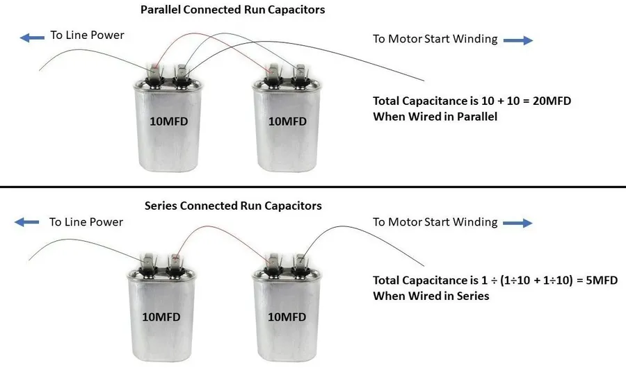
Analyzing capacitor circuits involves understanding how capacitors behave when connected in series and parallel configurations. The total or equivalent capacitance of these configurations differs significantly, impacting circuit behavior.
| Configuration | Description | Equivalent Capacitance Formula | Effect on Total Capacitance |
|---|---|---|---|
| Series | Capacitors connected end-to-end, sharing the same current path. | 1/C_eq = 1/C₁ + 1/C₂ + 1/C₃ + ... + 1/Cₙ | Total capacitance decreases; it is always less than the smallest individual capacitance. |
| Parallel | Capacitors connected side-by-side, sharing the same voltage. | C_eq = C₁ + C₂ + C₃ + ... + Cₙ | Total capacitance increases; it is the sum of individual capacitances. |
Understanding these configurations is crucial for predicting the behavior of capacitor networks within circuits. The choice between series and parallel arrangements allows engineers to manipulate the effective capacitance to meet specific design requirements.
The formulas provided above are derived from the fundamental principles of charge conservation and voltage division across capacitors. In a series connection, the charge stored by each capacitor is the same, whereas in parallel connection, the voltage across each capacitor is the same. These fundamental differences lead to distinct formulas for calculating total capacitance.
The behavior of capacitors in circuits is governed by fundamental formulas that relate charge, voltage, and capacitance. These equations are essential for analyzing and designing circuits. This section details these formulas and provides practical examples to illustrate their application.
The fundamental relationship between charge (Q), capacitance (C), and voltage (V) across a capacitor is given by the formula: Q = CV. Where: * Q is the charge stored on the capacitor in coulombs (C). * C is the capacitance in farads (F). * V is the voltage across the capacitor in volts (V).
The current (I) flowing through a capacitor is related to the rate of change of voltage across it, expressed as: I = C (dV/dt), where: * I is the current in amperes (A). * C is the capacitance in farads (F). * dV/dt is the rate of change of voltage with respect to time, measured in volts per second (V/s). This formula highlights that a current will only flow through a capacitor when the voltage across it is changing. In a DC circuit with constant voltage, the current through an ideal capacitor is zero after an initial charging phase.
Capacitors store energy in the electric field between their plates. The energy (E) stored in a capacitor is given by: E = 1/2 CV^2, where: * E is the energy stored in joules (J). * C is the capacitance in farads (F). * V is the voltage across the capacitor in volts (V).
| Parameter | Symbol | Formula | Unit |
|---|---|---|---|
| Charge | Q | Q = CV | Coulomb (C) |
| Capacitance | C | C = Q/V | Farad (F) |
| Voltage | V | V = Q/C | Volt (V) |
| Current | I | I = C (dV/dt) | Ampere (A) |
| Energy | E | E = 1/2 CV^2 | Joule (J) |
Consider a 100 μF capacitor initially uncharged. If a 12V voltage source is applied across it, the stored charge and the energy stored in capacitor can be calculated as follows. **Charge Calculation:** Using the formula Q = CV, where C = 100 μF = 100 × 10^-6 F and V = 12V, the charge Q = (100 × 10^-6 F) * (12 V) = 1.2 × 10^-3 C = 1.2 mC **Energy Calculation:** Using the formula E = 1/2 CV^2, the stored energy E = 0.5 * (100 × 10^-6 F) * (12 V)^2 = 0.0072 J = 7.2 mJ
This section addresses common inquiries regarding capacitor circuits, providing clear and concise answers to help clarify their functionality and application in electronics.
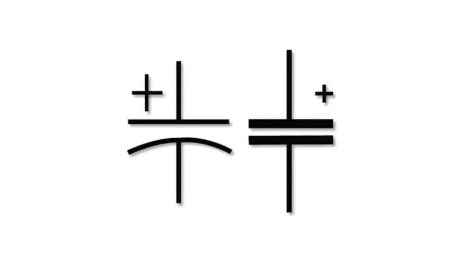
Understanding capacitor circuit diagrams and symbols is crucial for analyzing and designing electronic circuits. These diagrams provide a standardized visual representation of how capacitors are interconnected with other components, allowing engineers to interpret and build circuits efficiently. This section will cover the common symbols and interpretations found in circuit schematics.
Besides the basic symbol, understanding how capacitors are arranged in circuits is essential. In schematics, capacitors are shown alongside other components such as resistors, inductors, and voltage sources. These representations follow standard conventions to easily show connection points and circuit topology. The analysis of these circuits is based on applying the fundamental principles of circuit theory.
| Symbol | Description | Example Application |
|---|---|---|
| Two parallel straight lines | Non-Polarized Capacitor | General use, bypass capacitors |
| Two parallel lines with one curved | Polarized Capacitor (usually electrolytic) | Power supply filtering |
| Two parallel lines with an arrow through | Variable Capacitor | Tuning radio circuits |
Capacitor circuits are integral components within the world of electronics and energy. Their ability to store and release energy makes them vital in various functions such as filtering, timing, and energy storage. From basic DC blocking to complex AC coupling, capacitors are essential to every electronic device. With a better understanding of capacitor circuits, you'll be able to better appreciate how the complex modern world is put together, and be ready to tackle more advanced topics in circuit design.

