In the world of electronics, where signals dance between circuits, the coupling capacitor acts as a silent conductor, ensuring that only the desired AC signals pass while unwanted DC components are blocked. It's a bit like a sophisticated bouncer for electrons, letting the vibrant 'AC crowd' through while politely turning away the 'DC gatecrashers.' This article will explore the crucial role these tiny but mighty components play in circuit design, and we’ll uncover everything you need to know about them.
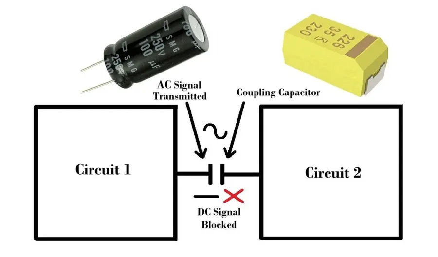
A coupling capacitor is a fundamental electronic component strategically employed to facilitate the transmission of alternating current (AC) signals while concurrently impeding the flow of direct current (DC) components between interconnected circuits or stages. Functionally, it operates as a high-pass filter, allowing high-frequency signals to pass while attenuating low-frequency and DC signals.
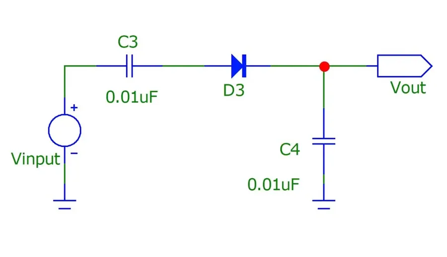
Coupling capacitors function as a selective filter, leveraging the fundamental principle that capacitors exhibit a high impedance to DC signals while presenting a low impedance to AC signals. This inherent property allows them to effectively block the flow of direct current while permitting alternating current to pass through. When a composite signal consisting of both AC and DC components is applied to a coupling capacitor, the capacitor obstructs the DC component, preventing it from reaching the subsequent circuit stage, whereas the AC component is allowed to propagate with minimal attenuation.
The behavior of a coupling capacitor can be understood through its impedance characteristics. The impedance (Z) of a capacitor is inversely proportional to the frequency (f) of the signal and the capacitance (C) value, as described by the formula: Z = 1 / (2πfC). At DC (0 Hz), the impedance is theoretically infinite, thus blocking any DC current. As the frequency increases, the impedance decreases allowing AC signals to pass more readily. This fundamental principle of frequency-dependent impedance is at the core of its operation as an AC coupling element.
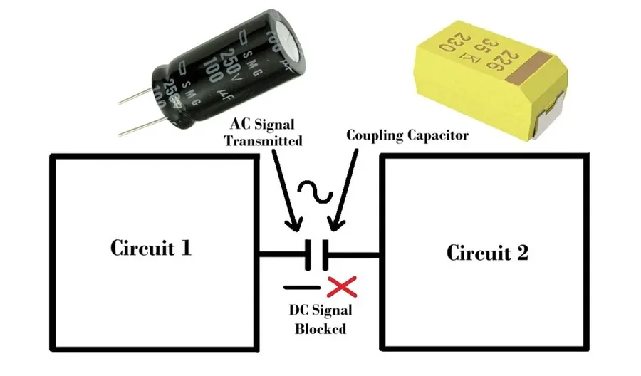
Coupling capacitors serve as essential components in a wide array of electronic applications, primarily for selectively allowing AC signals to pass while effectively blocking DC components. This characteristic is leveraged in diverse scenarios, from audio processing to high-speed data transmission, ensuring signal integrity and preventing unwanted DC bias from interfering with circuit operation.
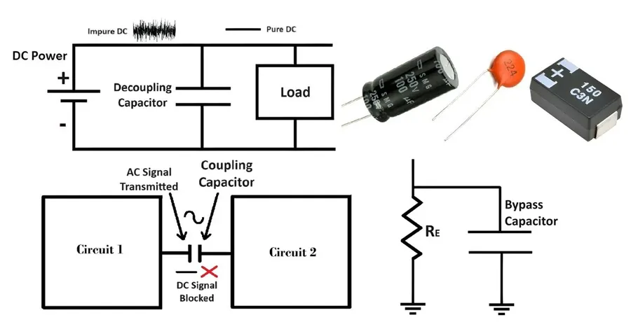
Coupling and decoupling capacitors, while both being capacitors, serve distinctly different roles in electronic circuits. Coupling capacitors are strategically employed to facilitate the transmission of AC signals between circuit stages while simultaneously impeding DC components. Conversely, decoupling capacitors are utilized to mitigate noise and stabilize DC power supplies, representing a fundamental difference in their intended functions and applications.
| Characteristic | Coupling Capacitor | Decoupling Capacitor |
|---|---|---|
| Primary Function | Pass AC signals, block DC | Filter noise, stabilize DC power |
| Signal Handling | Transmits AC signal between stages | Reduces AC noise on DC lines |
| DC Component | Blocks DC bias, preventing it from affecting subsequent stages | Stabilizes DC voltage by absorbing fluctuations |
| Placement | In series between circuit stages | In parallel with the power supply rail, near the IC or load |
| Impact | Signal isolation and AC signal transmission | Power supply stability and noise reduction |
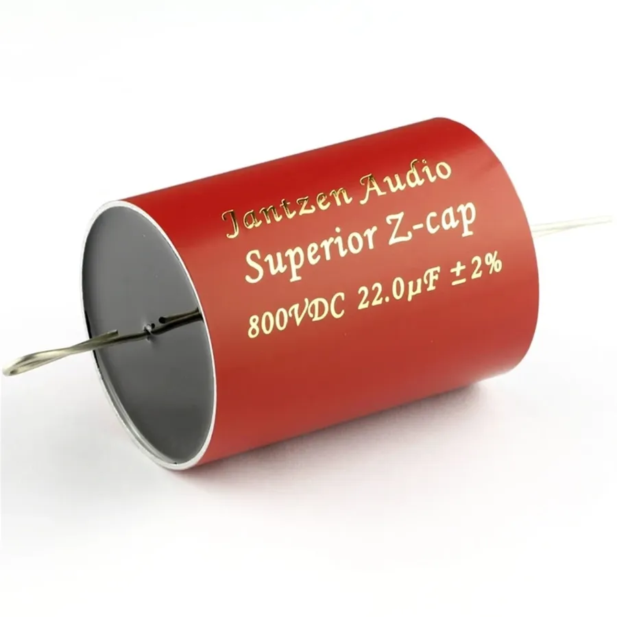
The selection of an appropriate coupling capacitor value is paramount for effective signal transfer, as this value dictates the capacitor's cutoff frequency, which in turn determines the range of AC frequencies allowed to pass between circuit stages. A meticulously chosen capacitor value ensures that desired AC signals are transmitted while unwanted DC components and lower frequency AC signals are effectively blocked.
| Capacitor Value | Cutoff Frequency | Impact on Signal | Typical Application |
|---|---|---|---|
| Lower Capacitance | Higher Cutoff Frequency | Blocks Lower Frequencies, Passes Higher Frequencies | High-frequency circuits, RF applications |
| Higher Capacitance | Lower Cutoff Frequency | Passes Lower Frequencies, Blocks DC | Audio circuits, low-frequency signal transmission |
The cutoff frequency (f_c) of a coupling capacitor in conjunction with a resistor is determined by the formula: f_c = 1 / (2πRC), where R is the resistance and C is the capacitance. This formula can be used to select a value of C to provide the desired cut off frequency.
The effectiveness of a coupling capacitor is significantly influenced by its physical placement within a circuit. Typically, these capacitors are installed in series between successive stages of an electronic circuit to selectively transmit the AC signal while effectively blocking any DC component. This series arrangement ensures that the AC signal is passed, allowing for stage-to-stage transmission while maintaining the DC bias of each stage.
Here are key considerations for coupling capacitor placement:
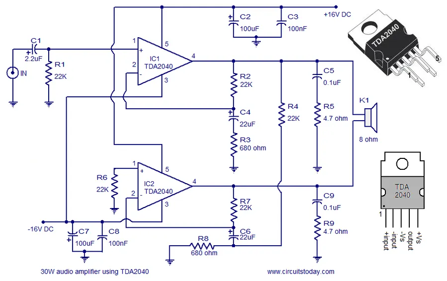
In audio circuitry, coupling capacitors are critical components, primarily serving to block DC offsets that can negatively impact signal fidelity. By preventing the amplification of DC components, these capacitors ensure that only the AC audio signal is passed between stages, resulting in a cleaner, less distorted output.
The selection of a coupling capacitor's value in audio applications is a critical design consideration. This value determines the capacitor's impedance at different audio frequencies. It must be appropriately chosen to pass the full range of frequencies of interest for optimal signal transfer, whilst avoiding signal loss or phase shift of the audio signal. An improperly chosen value can cause attenuation, particularly at low frequencies, resulting in a "thin" or diminished sound, while overly high values can lead to excessive signal leakage and instability.
The performance of coupling capacitors in audio circuits is often evaluated by considering factors including impedance, equivalent series resistance, and the type of capacitor material used. Ceramic, electrolytic, and film capacitors each have characteristics that influence audio signal quality. Film capacitors are favoured due to their lower distortion and stable behavior, but their large physical size may present constraints.
In summary, the strategic use of coupling capacitors in audio circuits is pivotal for achieving high-quality audio reproduction. Proper component selection and careful circuit design are crucial for optimal results.
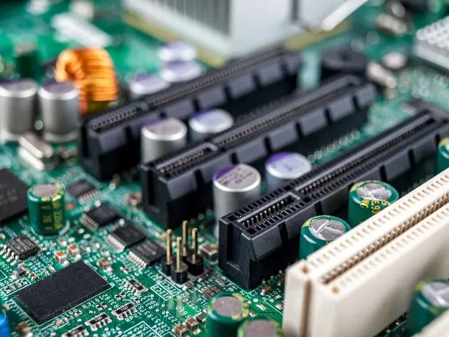
In high-speed data communication protocols such as Peripheral Component Interconnect Express (PCIe), coupling capacitors are essential for maintaining signal integrity and ensuring reliable data transmission. These capacitors play a critical role in isolating DC components and allowing high-frequency AC signals to pass through, which is vital for the proper function of PCIe lanes.
PCIe is a high-speed serial computer expansion bus standard that relies on differential signaling to achieve high data rates. Differential signaling involves transmitting a signal across two wires, where the signal is represented by the voltage difference between the wires. This approach is less sensitive to noise, but it requires that the signal remain AC-coupled to ensure the common-mode DC voltage does not interfere with the signal integrity. Coupling capacitors are placed in the differential pairs, in series with the signals, to achieve this.
| Feature | Description |
|---|---|
| Signal Integrity | Coupling capacitors preserve the shape of high-frequency data signals by blocking any DC offsets that could distort the waveform. This is critical for accurate data transmission in PCIe links. |
| DC Isolation | PCIe lanes can have different DC bias levels. Coupling capacitors ensure that these DC levels do not interfere with each other, preventing potential damage or functional issues. |
| Impedance Matching | By choosing appropriate capacitor values, they can also play a part in ensuring the impedance of the signal traces is correct, minimizing reflections. |
The selection of coupling capacitors in PCIe routing is crucial, requiring careful consideration of the capacitance value, voltage rating, and other parameters. The capacitance must be large enough to pass all the data frequencies within the PCIe standard, while also small enough to minimize physical size and cost, without causing signal degradation. These considerations ensure that PCIe-based devices can operate reliably and consistently. Placement of these capacitors should be very close to the driver, to maintain impedance control of the traces. This also ensures that any possible DC offset is removed prior to transmission.
This section addresses common questions regarding coupling capacitors, aiming to clarify their function, applications, and distinctions from similar components. We will explore these questions to provide a comprehensive understanding of coupling capacitors in various circuits.
Coupling capacitors, while seemingly simple components, can be the source of various circuit malfunctions if not functioning correctly. Identifying and rectifying these issues is critical for ensuring optimal circuit performance. This section provides guidance on diagnosing and addressing common problems associated with coupling capacitors.
When troubleshooting, always begin by verifying that the capacitor's physical characteristics and placement align with the schematic. Use appropriate tools, such as a multimeter, oscilloscope, and LCR meter, for measurements. It is often beneficial to replace the coupling capacitor with a known-good component of the correct value as a debugging step. Ensure the replacement capacitor meets the required specifications, including voltage rating, tolerance, and temperature coefficient.
The coupling capacitor, though small in size, holds a critical role in modern electronics by allowing the passage of AC signals while blocking DC components. Understanding how these components work, their applications, and how to properly select and integrate them into a circuit is an essential skill for any engineer. With the understanding of the principles we discussed, you are now equipped to fully leverage the power of the coupling capacitor in various scenarios, and ensure your circuits operate as intended.

