In the realm of electronics, the seemingly unassuming 100nF capacitor plays a critical role, acting as a guardian against unwanted noise and fluctuations in circuit power. Much like how a well-placed dam can smooth the flow of a river, this component, especially in its ceramic form, works to stabilize electronic signals. This article delves into the core of 100nF capacitors, covering their functionalities, variations, and their irreplaceable presence in countless electronic devices, from smartphones to complex industrial machinery. We'll unpack the essence of a 100nF capacitor, examining its construction, characteristics and applications.
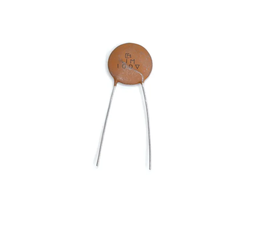
A 100nF capacitor, also expressed as 0.1µF (microfarad), is a fundamental electronic component designed to store electrical energy within an electric field. This specific capacitance value makes it a ubiquitous choice for various applications in electronic circuits, especially for decoupling and filtering purposes due to its favorable size and cost.
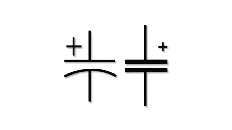
Capacitance, measured in Farads (F), is a fundamental property of electrical components that defines their ability to store an electrical charge. A 100nF capacitor, with a capacitance of 100 nanofarads, is capable of storing a specific amount of charge at a given voltage. This value dictates how quickly the capacitor can charge and discharge, influencing its behavior in circuits. The relationship between charge (Q), capacitance (C), and voltage (V) is defined by the formula Q = CV. Therefore, a 100nF capacitor will store 100 nano-coulombs of charge for every volt applied across it. This relationship is crucial in understanding a capacitors role in circuit behavior.
| Parameter | Description | Value |
|---|---|---|
| Capacitance | Ability to store charge | 100 nanofarads (nF) |
| Charge Storage | The amount of charge stored per volt | 100 nano-coulombs per volt |
| Charge-Discharge Rate | Relates to speed of energy storage and delivery | Influenced by capacitance, voltage, and current flow |
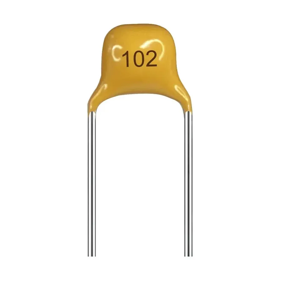
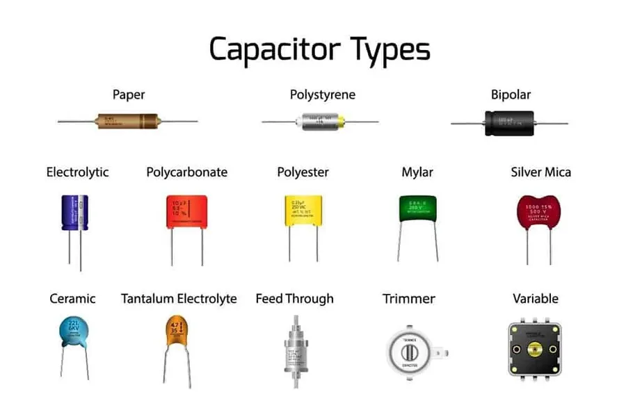
100nF capacitors are primarily available in two main types: ceramic and film. Each type exhibits distinct characteristics that make them suitable for different applications. The selection between ceramic and film capacitors hinges on the specific requirements of the circuit design, such as stability, tolerance, and frequency response.
| Feature | Ceramic Capacitors (including MLCC) | Film Capacitors |
|---|---|---|
| Size | Compact, available in small surface mount packages (e.g., 0402, 0603, 0805, 1206). | Larger, typically available in through-hole and larger surface mount packages. |
| Cost | Generally low-cost, making them suitable for high-volume production. | Typically more expensive than ceramic capacitors. |
| Stability | Less stable with temperature and voltage variations, capacitance can change. | More stable with temperature, voltage and frequency with low drift. |
| Tolerance | Wider tolerance range, typically ±5% to ±20%. | Tighter tolerance range, often ±1% to ±5%. |
| Frequency Response | Excellent high-frequency response, making them ideal for decoupling applications. | Good frequency response but can have higher ESR, which may affect high-frequency performance compared to MLCCs. |
| Applications | Decoupling, high-frequency filtering, general-purpose use. | Precision applications, audio circuitry, timing circuits. |
| Equivalent Series Resistance (ESR) | Very Low ESR making them great for decoupling | Higher ESR compared to MLCCs, which may influence high frequency performance |
| Temperature Coefficient | Capacitance may vary significantly with changes in temperature | Stable capacitance with temperature fluctuations, good for sensitive applications where temperature fluctuations are expected |
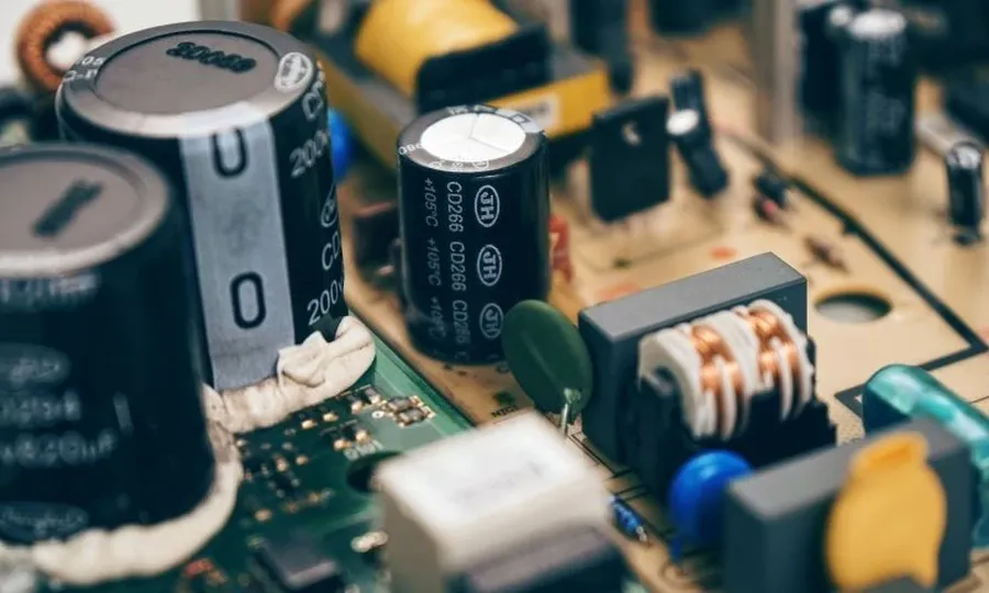
The 100nF capacitor's most critical function is decoupling, a process vital for ensuring the stable operation of electronic circuits. In this context, decoupling refers to the capacitor's ability to act as a localized energy reservoir for integrated circuits, effectively mitigating voltage fluctuations and high-frequency noise present on power rails. By strategically positioning a 100nF capacitor close to sensitive components, engineers ensure a stable and clean power supply, essential for the reliable performance of these elements.
The importance of decoupling stems from the inherent nature of electronic circuits. Rapid switching events, like those in digital logic, can cause transient voltage dips and spikes, as well as high frequency noise which can negatively impact the function of downstream components. Without a localized charge reserve, these fluctuations can propagate through the circuit, causing misoperations, data corruption, and overall circuit instability. The 100nF capacitor, in its decoupling role, acts as a buffer, absorbing these fluctuations and smoothing the power supply. This ability makes the 100nF capacitor a core component of any electronic design.
| Feature | Description |
|---|---|
| Primary Function | Decoupling: Providing a local energy reservoir near integrated circuits. |
| Noise Filtering | Primarily effective at attenuating high-frequency noise on power lines. |
| Placement | Strategically placed close to the power pins of integrated circuits. |
| Benefit | Ensures stable and reliable operation of sensitive electronic components by mitigating voltage fluctuations and high-frequency noise |
While the 100nF capacitor is predominantly known for its role in decoupling, its versatility extends to various other critical applications within electronic circuits. Its capacity to store and release electrical charge makes it suitable for shaping signals, regulating timing, and filtering frequencies.
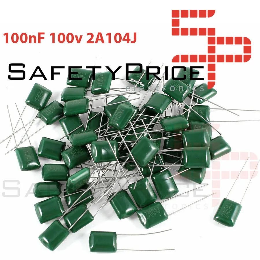
Capacitor markings are crucial for identifying their capacitance value. A 100nF capacitor is frequently represented using a numerical code, most commonly '104'. This code, when deciphered, indicates the capacitor's capacitance in picofarads (pF). Understanding these codes is essential for accurate component selection and sourcing.
| Code | Capacitance (pF) | Capacitance (nF) | Capacitance (uF) |
|---|---|---|---|
| 104 | 100000 | 100 | 0.1 |
| 103 | 10000 | 10 | 0.01 |
| 102 | 1000 | 1 | 0.001 |
The '104' marking is interpreted as follows: the first two digits, '10', form the base number, and the third digit, '4', is the multiplier, which represents the number of zeros to add to the base. So, '104' means 10 followed by four zeros, which equals 100,000 pF. Since 1nF equals 1000 pF, 100,000 pF is equal to 100nF. Conversely, 1 uF equals 1,000,000 pF or 1000 nF, hence 100nF equals 0.1 uF. While other less common coding conventions exist, they all aim to precisely represent the component's capacitance value in a standardized manner.
This section addresses common questions about 100nF capacitors, providing clear and concise answers to help users understand their properties, applications, and usage.
Selecting the appropriate 100nF capacitor requires careful consideration of several key parameters to ensure optimal performance and reliability within a given circuit. These factors include the operating voltage, temperature range, tolerance, and the capacitor's material type and construction, especially when specific application requirements are present, such as in high-frequency noise filtering or audio signal processing.
| Parameter | Description | Implications for 100nF Capacitor Selection |
|---|---|---|
| Operating Voltage | The maximum voltage the capacitor can safely withstand. | Ensure the voltage rating exceeds the maximum circuit voltage to prevent failure or degradation. Standard ratings are typically 10V, 16V, 25V, 50V, and 100V. Derating is common in high-reliability applications |
| Temperature Range | The range of temperatures within which the capacitor operates correctly. | Choose a capacitor that meets the circuit's operating temperature range. Ceramic capacitors typically have wider temperature ranges than film. Temperature stability, especially for high-precision analog circuits, should be a top priority. |
| Tolerance | The allowable deviation from the stated capacitance value. | Select a tolerance that meets the accuracy requirements of the circuit. Common tolerances are ±5%, ±10%, and ±20%. Tighter tolerance capacitors are preferred for time-sensitive applications. |
| Capacitor Type | The material and construction of the capacitor (e.g., ceramic, film). | Ceramic capacitors are small and inexpensive, suitable for decoupling and general use. Film capacitors offer better stability, higher accuracy, and low ESR, making them suitable for more sensitive applications, including audio filtering. MLCC(Multi-Layer Ceramic Capacitors) are the most commonly used. |
| Equivalent Series Resistance (ESR) | The internal resistance of the capacitor, which affects its ability to handle high-frequency currents. | A low ESR capacitor is preferable for decoupling and high-frequency noise filtering, especially in power supply and sensitive analog circuits. ESR impacts transient response. |
| Size | The physical size of the component, often defined by package type | Surface Mount Device (SMD) components with standard sizes such as 0805, 0603, 1206 and through-hole are the most common. Choose a physical size based on the PCB footprint design and application requirements |
For instance, in audio circuits where high fidelity is paramount, a film capacitor with a low ESR and tight tolerance would be preferred over a ceramic capacitor. Conversely, for a simple digital logic circuit decoupling applications, a standard ceramic MLCC capacitor will suffice. The correct choice ensures the stable performance of the electronic circuit.
When electronic circuits malfunction, a 100nF capacitor is often a prime suspect due to its common use in decoupling and filtering. Identifying a faulty 100nF capacitor requires systematic checks for common failure modes, and replacement needs careful attention to specifications to maintain circuit integrity.
In summary, the 100nF capacitor, often found as a ceramic component, is a cornerstone of modern electronics. Its decoupling functionality stabilizes power, while its compact size and low cost make it a go-to choice. Whether you're working on a complex design or a basic project, understanding the crucial role of the 100nF capacitor is fundamental. It’s clear that this component, even in its unassuming form, embodies the essence of circuit design—smoothing out the fluctuations and ensuring stable electronic flow in a world powered by intricate electronic processes.

