In today's technology-driven world, a sudden power outage can disrupt critical systems. This is where the Uninterruptible Power Supply (UPS) comes into play, and at the heart of every UPS system lies a vital component: the UPS PCB. This article explores the core functions of the UPS PCB, its intricate design, and its essential role in maintaining power continuity. We'll delve into how this unassuming board ensures that your devices remain operational when the main power fails.
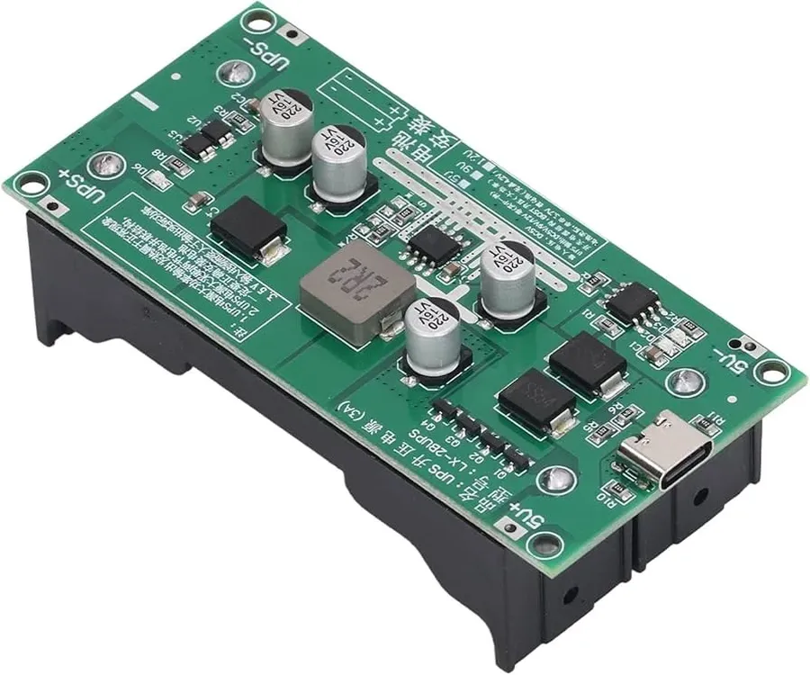
The Uninterruptible Power Supply (UPS) Printed Circuit Board (PCB) serves as the central nervous system of a UPS system, orchestrating critical functions to ensure a seamless power transition during outages. Specifically, the UPS PCB is responsible for managing battery charging, DC to AC power inversion, power source switching, system monitoring, and communication with external devices, thus guaranteeing a continuous and stable power supply.
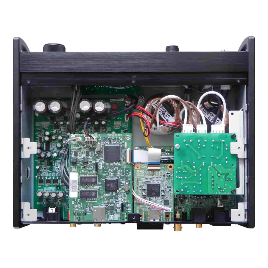
A UPS (Uninterruptible Power Supply) PCB (Printed Circuit Board) is a complex assembly integrating various electronic components, each playing a vital role in ensuring reliable power delivery. These components work in concert to manage power flow, battery charging, and system protection.
| Component | Function | Importance |
|---|---|---|
| Microcontroller (MCU) | Acts as the central processing unit, managing overall system operation, monitoring parameters, and executing control logic. | Crucial for intelligent decision-making within the UPS, such as switching between mains and battery power. |
| Battery Management System (BMS) | Monitors battery voltage, current, and temperature during charging and discharging; ensures battery safety and optimal performance. | Essential for extending battery lifespan and preventing damage due to overcharging or deep discharging. |
| Inverter Circuitry | Converts DC (Direct Current) power from the battery to AC (Alternating Current) power to supply connected loads during power outages. | Vital for providing stable AC power when the mains power fails. |
| Protection Circuits | Includes overcurrent, overvoltage, and short-circuit protection, preventing damage to the UPS and connected equipment. | Critical for safety, ensuring that the UPS and load equipment are protected from electrical faults. |
| Communication Interfaces | Facilitates data exchange with external devices (such as computers or monitoring systems), enabling remote status monitoring and control. | Provides network or communication capabilities for advanced control or remote access capabilities. |
| Rectifier | Converts AC mains power to DC power for charging the battery. | Fundamental for the charging process when the main power is available. |
| Switching Components (e.g., Relays, MOSFETs) | Enable automatic switching between mains power and battery power. | Key for automatic, seamless transition between sources to avoid downtime. |
| Voltage Regulators | Maintain stable voltage levels for the various circuits within the UPS PCB. | Ensures all components receive their designated supply voltages to function properly. |
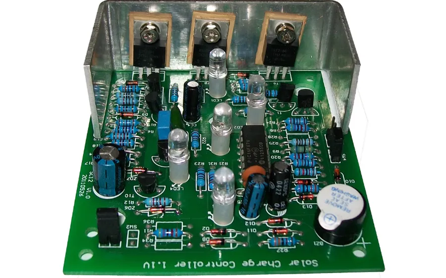
The UPS Printed Circuit Board (PCB) is instrumental in managing power flow within an uninterruptible power supply system. It intelligently orchestrates the transition between mains power and battery backup during power disruptions, ensuring a continuous and stable power supply to connected devices. This involves not only seamless switching but also precise voltage regulation and controlled battery management.
| Function | Description | Key Components Involved |
|---|---|---|
| Mains Power Monitoring | Continuously checks the availability and quality of the incoming AC power. It ensures that the voltage and frequency are within acceptable limits for normal operation. | Microcontroller, Voltage Sensors |
| AC-to-DC Conversion | Converts the incoming AC mains power into DC power for both charging the battery and providing DC power to certain internal components. | Rectifier Circuit, Smoothing Capacitors |
| Battery Charging | Manages the charging cycle of the battery, ensuring optimal charge levels are maintained. It also prevents overcharging or deep discharge to maximize battery life and performance. | Battery Management System (BMS), Charger Controller |
| Inverter Operation | Transforms the DC battery power back into AC power for output during mains power failures. This process involves generating a sine wave that closely matches the mains voltage and frequency. | Inverter Circuit, Switching Transistors |
| Power Switching | Controls the automatic transfer between mains and battery power. It switches to battery power instantly upon a mains failure and then back to mains power when it is restored, maintaining uninterrupted power flow. | Relays, Switching Circuitry |
| Voltage Regulation | Stabilizes the output voltage of the UPS regardless of whether the source is mains or battery. This is critical for protecting sensitive equipment from voltage spikes or sags. | Voltage Regulators, Feedback Control |
| Battery Monitoring | Continuously monitors battery health, including voltage, current, and temperature. It ensures efficient and safe battery operation and provides alerts for battery-related issues. | BMS, Current Sensors, Temperature Sensors |
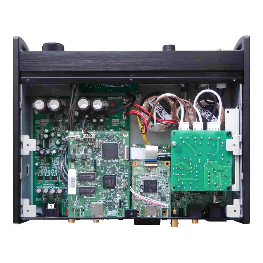
Designing a robust UPS PCB necessitates meticulous attention to several critical factors, ensuring the system's reliability and longevity. These considerations encompass thermal management, efficient power conversion, and judicious component selection, all of which are paramount for withstanding the demanding conditions of UPS operation. Given the high current loads and the inherent heat generation during operation, a well-engineered design is crucial for sustained performance and prevention of component failures.
| Design Consideration | Description | Importance |
|---|---|---|
| Thermal Management | Efficient heat dissipation using heat sinks, thermal vias, and strategic component placement. | Prevents overheating, ensures component reliability, and extends PCB lifespan. |
| Power Conversion Efficiency | Use of high-efficiency switching regulators and inverters to minimize power losses. | Reduces heat generation, improves overall UPS efficiency, and minimizes energy consumption. |
| Component Selection | Choosing components with suitable voltage and current ratings, temperature tolerances, and reliability. | Ensures stable operation under varying loads and environmental conditions and minimizes failures. |
| High Current Load Management | Designing PCB traces and vias that can handle the required current with minimal voltage drop. | Prevents trace burnout and voltage drops, maintaining stable operation during load shifts. |
| EMI/EMC Compliance | Implementation of proper shielding, filtering, and grounding techniques to minimize electromagnetic interference. | Reduces interference with other devices and ensures system stability. |
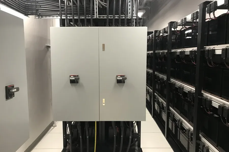
UPS PCBs are crucial components in a wide array of applications, safeguarding sensitive electronics from power disruptions. Their adaptability allows them to protect everything from individual home computers to complex industrial machinery, making them essential for maintaining operational continuity and preventing data loss. Each application has unique power needs, requiring variations in UPS PCB design to meet specific demands.
| Application Area | Specific Usage | PCB Design Considerations |
|---|---|---|
| Home and Office | Desktop PCs, laptops, routers, peripherals | Smaller size, moderate power handling, emphasis on cost-effectiveness |
| Data Centers | Servers, networking equipment, storage arrays | High power capacity, redundancy features, robust protection circuits |
| Industrial Automation | PLCs, industrial robots, process control systems | Rugged design, high reliability, tolerance to harsh environments, ability to handle high inrush currents |
| Medical Equipment | Patient monitoring systems, diagnostic equipment, life support devices | High reliability, compliance with medical device standards, stringent safety features |
| Telecommunications | Base stations, telecom switches, network infrastructure | Remote management, extended runtime, weather protection |
| Retail and Point of Sale | Cash registers, payment processing systems, inventory scanners | Compact size, stable power supply, reliable operation during peak hours |
Ensuring the longevity and reliability of a UPS system hinges on the proper maintenance and troubleshooting of its Printed Circuit Board (PCB). Regular inspections and proactive measures can prevent common issues, keeping the system operational and minimizing downtime. This section outlines key areas for inspection and effective troubleshooting practices.
This section addresses common questions regarding UPS PCBs, clarifying their critical functions, potential issues, and best maintenance practices. Understanding these aspects is key to ensuring the reliable operation of your uninterruptible power supply.
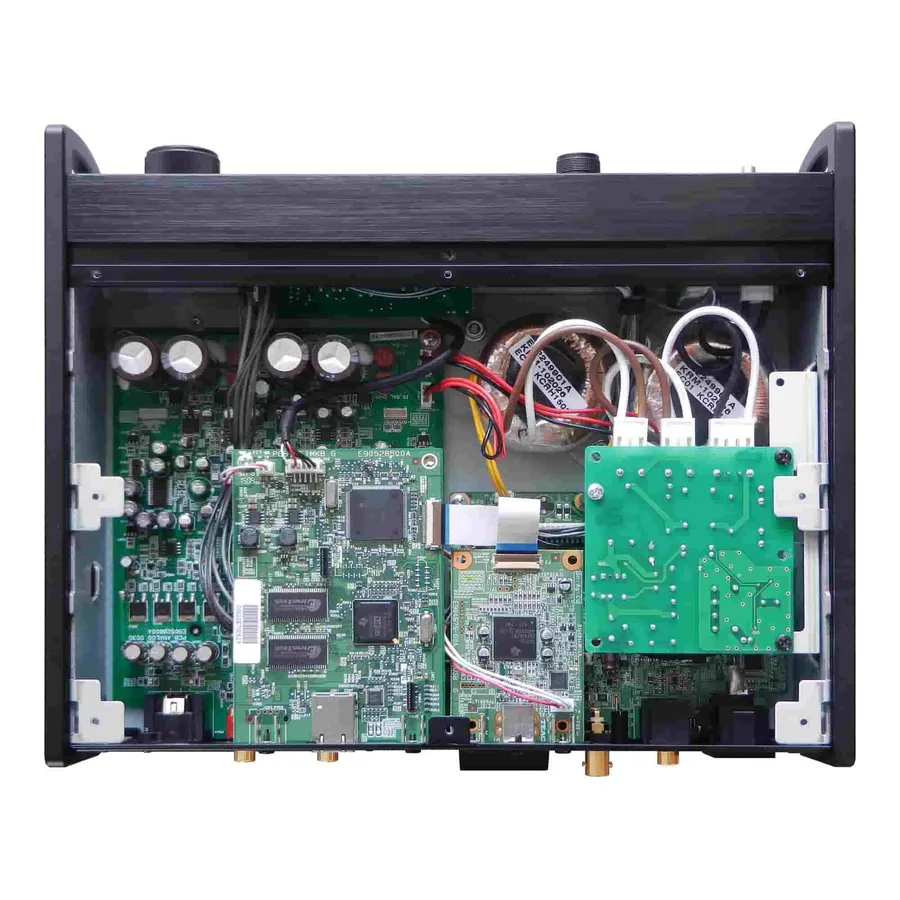
The landscape of UPS PCB technology is rapidly evolving, driven by the ever-increasing demands for more efficient, reliable, and compact power solutions. Future trends are focusing on miniaturization, enhanced efficiency, intelligent monitoring, and advanced materials to improve overall performance and longevity.
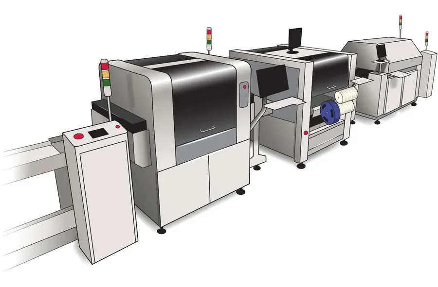
The decision between assembling a UPS PCB yourself and utilizing a professional PCBA manufacturer involves a careful evaluation of cost, complexity, expertise, and quality control. Each approach presents distinct advantages and disadvantages that must be weighed against project requirements.
| Factor | DIY UPS PCB Assembly | Professional PCBA Manufacturing |
|---|---|---|
| Cost | Potentially lower for simple designs, but higher for complex ones due to errors and rework. | Higher initial cost, but potential for cost savings on large production runs and reduced errors. |
| Complexity | Suitable for simple designs, may become extremely difficult for complex multi-layer PCBs with surface mount components. | Capable of handling high complexity designs with sophisticated technologies such as multi-layer boards and fine pitch components. |
| Expertise Required | Requires a high level of knowledge in electronics, PCB design, component handling, and soldering techniques. | Utilizes the experience of skilled technicians and engineers who understand and are proficient in PCB manufacturing best practices. |
| Quality Control | Quality control depends entirely on the assembler’s skills, resources, and tools, leading to inconsistent results. | Strict quality control protocols, including automated testing, and X-ray inspections, to assure the production of high-quality, reliable PCBs. |
| Component Sourcing | The responsibility of component sourcing is with the assembler and may result in the use of unqualified suppliers and counterfeit components, potentially reducing reliability. | Professional manufacturers have established relationships with reputable suppliers and provide Certificates of Conformity, ensuring high component quality and reliability. |
| Turnaround Time | Longer assembly times that can be unpredictable and inconsistent due to human limitations and process variations. | Faster and consistent turn around times, which can ensure a faster product launch, or project timeline. |
| Equipment | Requires investment in soldering stations, rework equipment, inspection equipment, and other tools. Cost may be prohibitive for hobbyists. | Manufacturer has all of the necessary specialized equipment such as pick and place machines, reflow ovens, and other necessary tools. |
The UPS PCB is the unsung hero behind the continuous operation of our devices. From managing power transitions to ensuring efficient battery usage, its role is indispensable. Understanding its intricacies and design considerations will be crucial in maintaining the reliability of our electrical systems. As technology advances, the UPS PCB will continue to evolve, playing an increasingly important role in our connected world. A well-maintained UPS PCB, along with the UPS system that it works within, guarantees uninterrupted operation, and peace of mind.

