In the world of electronics, single sided PCBs (Printed Circuit Boards) are the workhorses behind countless devices, from simple household appliances to sophisticated industrial equipment. Choosing the right single sided PCB manufacturer is critical to ensure the quality, reliability, and cost-effectiveness of your product. This guide will delve into the intricacies of single sided PCB manufacturing, providing a comprehensive overview to help you make informed decisions, and highlighting the importance of choosing a qualified partner.
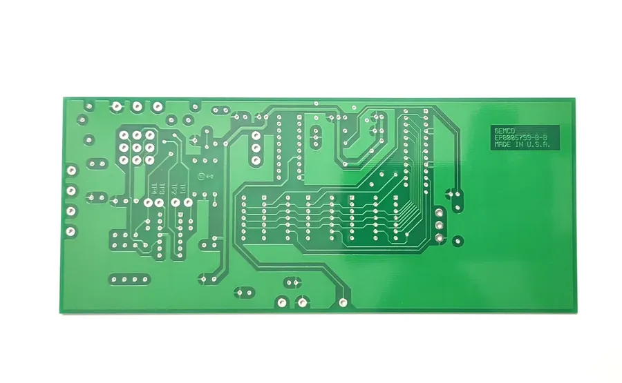
Single-sided PCBs are the foundational building blocks of many electronic devices, characterized by their conductive layer on just one side of the insulating substrate. This design simplicity lends itself to various applications, making them a cost-effective and reliable solution for numerous electronic needs. Their construction typically involves a base material, conductive traces, and a protective solder mask, designed for straightforward component assembly and soldering processes.
These PCBs are widely used in applications where circuit complexity and density are not paramount. Their ease of manufacturing and lower cost make them ideal for consumer electronics, such as simple lighting circuits, basic audio equipment, and control panels. The suitability of single-sided boards often comes down to the complexity of the electronic device's functionality and performance requirements.
| Characteristic | Description |
|---|---|
| Structure | Conductive layer on one side of the substrate |
| Materials | Typically FR-4, CEM-1, or similar |
| Components | Mounted on one side, soldered to exposed traces |
| Common Applications | Lighting, simple control circuits, basic audio equipment |
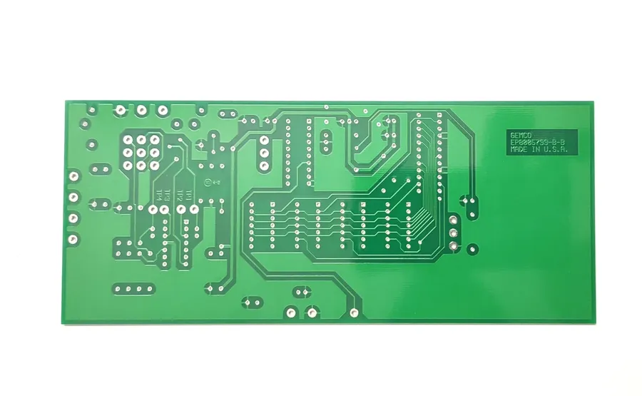
Designing single-sided PCBs requires careful planning to maximize performance within the constraints of a single conductive layer. Key design considerations include trace geometry, component placement, and thermal management, all of which impact the board's functionality and reliability. The limitations of single-sided boards necessitate efficient use of space and strategic design choices.
Achieving optimal performance on a single-sided PCB involves a strategic approach to several key design elements. This includes considerations for trace width and spacing to ensure signal integrity and prevent shorts, optimal component placement for effective routing and minimal interference, and careful thermal management to avoid hotspots and ensure board reliability.
Best practices for single-sided PCB design include utilizing design software that supports autorouting (with careful review and adjustment), creating a schematic first, and meticulously checking for errors before fabrication. Furthermore, collaborating with experienced designers or engineers who are familiar with the limitations and nuances of single-sided PCB layouts is highly beneficial.
| Aspect | Consideration |
|---|---|
| Trace Width | Determined by current requirements; wider traces for higher currents |
| Trace Spacing | Should meet minimum spacing requirements to avoid shorts and signal interference |
| Component Placement | Minimize trace length, group related components, consider thermal effects |
| Thermal Relief | Use thermal vias and heat sinks to dissipate heat effectively |
| Signal Routing | Avoid signal crossings, maintain proper impedance matching, avoid sharp angles |
| Design Tools | Use software with autorouting and error-checking functions |
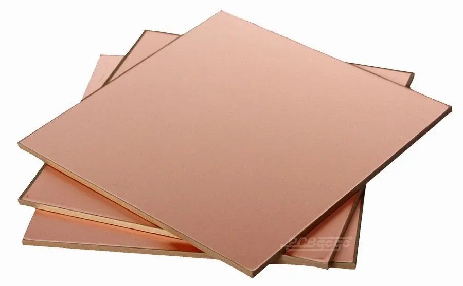
The selection of base materials in single-sided PCB manufacturing is critical, directly influencing performance, durability, and cost. These materials primarily consist of a substrate that provides mechanical support and an insulating layer upon which conductive traces are etched.
| Material | Description | Typical Applications | Advantages | Disadvantages |
|---|---|---|---|---|
| FR-4 | Flame Retardant-4, a glass-reinforced epoxy laminate. | General-purpose electronics, consumer goods, and industrial applications. | Excellent mechanical strength, good electrical properties, cost-effective. | Not suitable for very high frequency applications or high temperature |
| CEM-1 | Composite Epoxy Material-1, made from paper and epoxy resin. | Less demanding applications, like lighting and lower frequency electronics. | More cost-effective than FR-4, easy to process. | Lower mechanical strength and less temperature resistance than FR-4. |
| Phenolic Paper | Paper-based laminate with a phenolic resin. | Basic, low-cost applications, like toys, or simple household devices. | Very low cost. | Poor moisture resistance, low flexural and mechanical strength. |
| Metal Core (Aluminum/Copper) | Metal substrate with a thin insulating layer. | LED lighting, power electronics, and high thermal management applications. | Excellent heat dissipation, robust mechanical structure. | Higher cost and more complex processing. |
The properties of these materials are crucial for the functionality of the PCB. For instance, FR-4 offers a good balance of mechanical strength and electrical insulation, making it a common choice for a wide range of applications. CEM-1, while more cost-effective, may be preferred in simpler applications where high performance is not critical. Metal core PCBs are ideal when thermal dissipation is important, such as in high-power electronic designs.
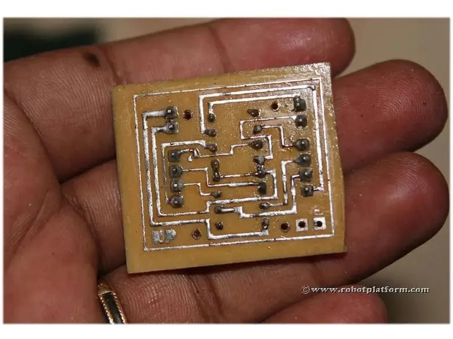
The fabrication of single-sided PCBs involves a series of precise steps to transform a design concept into a functional circuit board. This process, while simpler than that of double-sided or multilayer PCBs, still requires meticulous execution and quality control to ensure reliability.
Quality control is paramount in each of these steps. Manufacturers utilize techniques such as Automated Optical Inspection (AOI), and electrical continuity testing to identify and rectify any potential issues before the product reaches the customer. This ensures that each PCB meets the required specifications and performance standards.
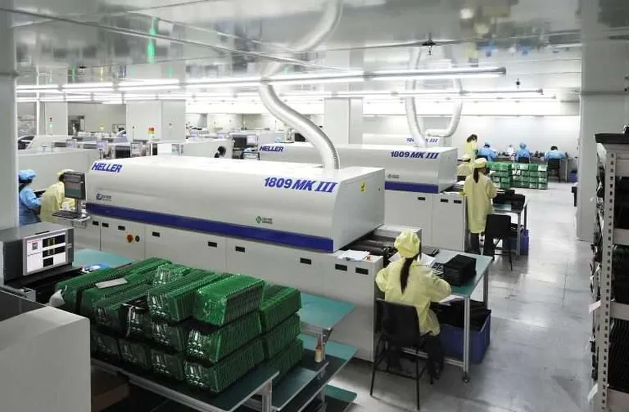
Selecting the right single-sided PCB manufacturer is crucial for ensuring the quality, reliability, and cost-effectiveness of your electronic product. This decision involves a careful evaluation of several key factors, including pricing, lead times, quality certifications, communication effectiveness, and the manufacturer's production capabilities. This section provides guidance on navigating these considerations to make an informed choice that aligns with your specific needs and constraints.
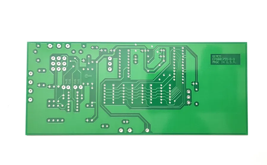
Optimizing the cost of single-sided PCB manufacturing is crucial for many applications. This section explores the primary cost drivers and offers strategies to minimize expenses without compromising board quality. A thorough analysis of these factors can lead to significant savings.
Key cost drivers include material selection, manufacturing volume, design complexity, and the choice of manufacturer. Understanding how these factors affect the final price can help businesses make informed decisions.
| Cost Driver | Impact on Cost | Optimization Strategies |
|---|---|---|
| Base Material | Higher performance materials (e.g., FR-4 with higher Tg) increase cost. CEM-1 is usually less expensive. | Use cost-effective materials (e.g., CEM-1 where applicable) . Evaluate whether high-performance is truly necessary for your application. |
| Manufacturing Volume | Larger production runs generally have lower per-unit costs due to economies of scale. | Consolidate orders to increase the total volume, take advantage of bulk pricing. |
| Design Complexity | Complex designs with numerous vias, tight spacing, or unusual shapes increase production time and material usage. | Simplify designs where feasible, optimizing for standard shapes and avoiding tight tolerances. Work with a design engineer before fabrication to optimize the design. |
| Manufacturer Location | Domestic manufacturers may have higher costs but offer faster turnaround and better communication; overseas manufacturers usually provide lower per-unit costs but may require larger minimum orders, slower lead times, and additional shipping costs. | Evaluate project needs (lead time vs. cost) and choose a manufacturer that best aligns with those needs. Factor in shipping costs and logistics. |
| Surface Finish | Different surface finishes such as HASL (Hot Air Solder Leveling), ENIG (Electroless Nickel Immersion Gold), or OSP (Organic Solderability Preservative) have different costs. | Select a surface finish based on application requirements. Use OSP when possible for cost-effectiveness, or HASL if your solderability needs are critical. |
| Testing Requirements | Different levels of testing including flying probe, and bed of nail testing have different costs. | Select testing based on requirements, some less complex boards may not need full testing. |
Strategies for cost reduction include optimizing material selection, which can significantly impact cost without compromising functionality. For example, using CEM-1 instead of FR-4 can reduce cost, if application requirements permit. Design for Manufacturability (DFM) is also crucial; simpler designs with standard shapes and component spacing not only reduce costs, but improve yield. Purchasing in larger volumes will also lead to lower per unit costs. Finally, comparing quotes from multiple suppliers helps identify more competitive pricing.
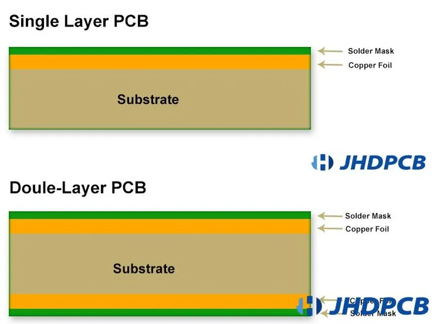
Single-sided PCBs and double-sided PCBs represent fundamental choices in electronic circuit board design, each offering distinct advantages and disadvantages that align with specific application requirements. The selection between these two types hinges on factors such as circuit complexity, component density, cost constraints, and performance needs. Understanding the nuances of each will ensure optimal design choices.
| Feature | Single-Sided PCB | Double-Sided PCB |
|---|---|---|
| Layer Count | One conductive layer | Two conductive layers |
| Complexity | Lower complexity, simpler designs | Higher complexity, more intricate designs |
| Routing | Limited routing options; all traces on one side | Increased routing options; traces on both sides, vias for layer transitions |
| Component Density | Lower component density | Higher component density |
| Cost | Generally lower cost | Generally higher cost |
| Performance | Suitable for simple, low-density circuits | Suitable for complex, high-density circuits, better signal integrity |
| Applications | Basic electronics, simple circuits, cost-sensitive applications | Advanced electronics, complex circuits, where performance matters |
| Heat Dissipation | Limited heat dissipation capabilities | Better heat dissipation due to more surface area and vias |
Key differentiators extend beyond the number of conductive layers. Double-sided PCBs, with their ability to route traces on both sides and interconnect layers via vias, allow for more compact designs and greater circuit complexity. Single-sided PCBs, while simpler, present challenges in achieving high-density designs and optimal signal integrity. The cost implications also vary; single-sided boards are generally more cost-effective for simple applications, while double-sided boards, although more expensive, are indispensable for complex, high-performance electronic devices. When choosing, designers need to evaluate the trade-offs, considering not just the immediate cost but also long-term functionality and system demands.
This section addresses common inquiries regarding single-sided PCBs, covering their manufacturing, cost-effectiveness, applications, and comparisons to double-sided PCBs. We'll provide clear, concise answers to help you make informed decisions about using single-sided PCBs.
Choosing the right single sided PCB manufacturer is essential for a successful product launch. By understanding the design, manufacturing, and cost considerations, along with the key factors to assess potential partners, you can ensure that your PCBs meet your specifications and budget. Partnering with a reputable single sided PCB manufacturer is crucial for getting quality, low-cost parts for your electronics and hardware needs. A well-chosen single sided PCB manufacturer can help you optimize your designs and product to go to market faster and cheaper.

