
As automotive TPMS modules shrink while demands for extreme reliability grow, designers face the critical intersection of miniaturization and mission-critical performance. This article decodes the complex DFM challenges inherent in tire pressure sensing, providing a roadmap for high-yield manufacturing.
The Unique Challenges of TPMS Module Design
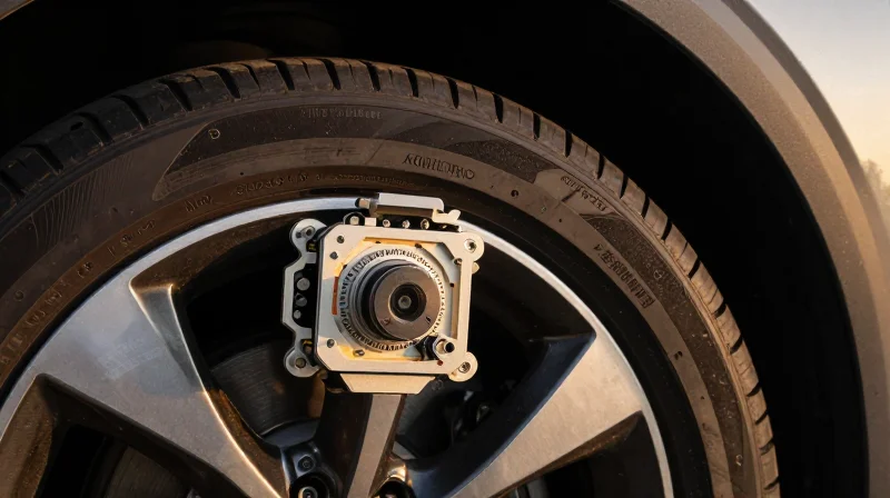
The Harsh Reality of Tire-Mounted Environments
Designing PCBs for TPMS modules represents one of the most demanding challenges in automotive electronics. Unlike chassis-mounted controllers, tire-mounted sensors operate in a dynamic environment characterized by high-frequency vibration, massive centrifugal forces, and rapid temperature fluctuations that can compromise solder integrity and material stability.
Key Environmental Stress Factors
| Stress Factor | Physical Impact | PCB Design Implication |
|---|---|---|
| Centrifugal Force | High G-load structural fatigue | Requires rigid substrate and optimized component orientation |
| Thermal Cycling | Coefficient of Thermal Expansion (CTE) mismatch | Mandates specialized laminates and stress-relief pad design |
| High-Frequency Vibration | Solder joint cracking and micro-fractures | Necessitates advanced underfill and robust anchoring |
Addressing Mechanical Reliability
The primary goal in TPMS PCB design is to minimize mechanical strain on interconnections. This requires a departure from standard consumer-grade DFM practices, prioritizing structural integrity through precise pad geometries and component placement strategies that avoid high-stress zones.
- How does vibration affect solder longevity?
Continuous high-frequency vibration leads to work hardening of the solder alloy, eventually causing brittle fatigue cracks at the component-to-PCB interface. - Why is CTE matching critical?
Rapid temperature swings between -40°C and +125°C cause differential expansion between the PCB substrate and copper traces, which can shear solder joints if material coefficients are not aligned. - What role does centrifugal force play?
At high wheel RPM, the massive outward G-force induces board flexing, requiring heavy-duty localized board stiffening and balanced mass distribution to prevent PCB warping.
Material Selection Strategy
For high-reliability TPMS applications, selecting the appropriate dielectric material is as important as the circuit layout itself. High glass transition temperature (Tg) materials are essential to ensure the PCB remains dimensionally stable during the extreme thermal excursions encountered on the road. Engineers must prioritize laminates that exhibit low Z-axis expansion to protect internal via structures from cracking under cyclic thermal stress.
Optimizing Micro-via Reliability in HDI Boards
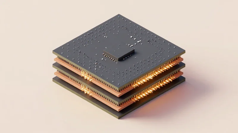
Managing Micro-via Aspect Ratios for Thermal Fatigue
In TPMS applications, the Coefficient of Thermal Expansion (CTE) mismatch between the dielectric material and the copper barrel is the primary driver of micro-via failure. To mitigate fatigue, maintain a strict micro-via aspect ratio not exceeding 0.75:1. Exceeding this limit restricts the effective deposition of electrolytic copper, leading to thin plating walls that crack under repeated thermal cycling.
| Parameter | Recommended Constraint | Rationale |
|---|---|---|
| Max Aspect Ratio | 0.75:1 | Ensures reliable copper plating depth. |
| Minimum Plating Thickness | 25 µm (1 mil) | Prevents barrel cracking under strain. |
| Via Target Land | Via diameter + 100 µm | Provides necessary registration tolerance. |
Symmetrical Stack-ups and Structural Integrity
Asymmetric stack-ups are a critical failure point in tire-mounted modules. During extreme temperature fluctuations, imbalances in copper distribution cause board warping, which imparts stress directly onto the micro-vias. Utilize a strictly balanced stack-up design where copper density is mirrored across the PCB neutral axis. This practice minimizes internal stresses that lead to latent barrel cracks and interfacial delamination.
Best Practices for Reliability: Frequently Asked Questions
- How does via-in-pad plating impact reliability?
Always perform copper-filled via-in-pad (VIPPO) processes followed by cap plating. This prevents solder wicking and creates a solid, robust structure that withstands the high-g vibration environment of a rotating tire. - What is the optimal surface finish for TPMS?
Electroless Nickel Immersion Gold (ENIG) or Electrolytic Nickel/Gold are preferred. Avoid HASL due to uneven surface planarization, which compromises via integrity in HDI high-density designs. - How can we verify plating quality post-manufacturing?
Standard electrical testing is insufficient. Implement cross-sectional micro-analysis and thermal stress testing (e.g., IST - Interconnect Stress Test) on coupons to detect plating voids before volume assembly.
Precision Impedance Control for RF Antenna Integrity

Maintaining 50-Ohm Trace Integrity
To ensure reliable wireless communication in tire pressure monitoring systems, the transmission line between the RF IC and the antenna must maintain a consistent 50-ohm characteristic impedance. Because TPMS modules are subjected to extreme thermal fluctuations, the dielectric constant (Dk) of standard FR-4 substrates can shift significantly, resulting in impedance mismatch. Designers must utilize high-Tg materials with stable Dk values and implement micro-strip or coplanar waveguide geometries that compensate for manufacturing tolerances, such as copper etching variations.
Design Techniques for Impedance Stability
| Technique | Primary Benefit | Manufacturing Consideration |
|---|---|---|
| Coplanar Waveguide | Improved shielding and EMI control | Requires strict gap-to-trace clearance |
| Laminate Selection | Thermal stability of Dk | Higher material costs |
| Controlled Etch Bias | Consistent trace width | Requires vendor-specific etch data |
Critical Implementation Strategies
- How does temperature affect impedance?
As temperature increases, the Dk of common laminates changes, altering the propagation velocity and shifting the impedance; utilizing specialized RF-grade laminates minimizes these fluctuations. - What role does surface finish play?
Finish thickness and composition can affect high-frequency skin effect losses, so ENIG or immersion silver is preferred for maintaining surface geometry integrity. - How can designers verify consistency?
Include impedance test coupons on the panel rail to allow for TDR (Time Domain Reflectometry) verification against target specifications before board singulation.
Final signal integrity validation must account for parasitic capacitance introduced by soldermask layers. In high-frequency TPMS designs, specifying a low-loss, thin soldermask or excluding mask from the RF transmission line path is a best practice to prevent unexpected dielectric loading on the antenna feed.
Material Selection for High-Temperature Automotive Environments
Thermal Stability and Tg Requirements
In-wheel Tire Pressure Monitoring Systems (TPMS) are exposed to extreme operational temperature swings, ranging from freezing winter conditions to the intense frictional heat generated by braking and road contact. Standard FR-4 materials are insufficient for these applications, as their low glass transition temperature (Tg) causes rapid Z-axis expansion. This expansion leads to barrel cracking in micro-vias and delamination at the copper-to-dielectric interface. Designers must specify high-Tg laminates, typically ranging from 170°C to 180°C, to ensure the substrate remains in a rigid, stable state throughout the service life of the vehicle.
Comparative Tracking Index (CTI) and Reliability
Beyond thermal resistance, the Comparative Tracking Index (CTI) is a vital metric for automotive high-reliability boards. High CTI values (typically >600V) indicate that a material can withstand surface electrical stress without forming conductive paths (tracking) when moisture or contaminants infiltrate the assembly. Given the proximity of TPMS sensors to brake dust, road salt, and moisture, selecting a high-CTI material is non-negotiable for preventing internal short circuits and leakage current degradation.
| Material Property | Standard FR-4 | High-Rel Automotive Laminate |
|---|---|---|
| Glass Transition (Tg) | 130°C - 140°C | 170°C - 180°C |
| CTI Rating | 175V - 250V | 600V+ |
| CTE Z-Axis | High (Unstable) | Low (Controlled) |
| Thermal Cycling | Prone to Cracking | Resilient |
Common Material Selection FAQs
- Why is Tg not the only metric that matters?
While Tg measures the softening point, the Coefficient of Thermal Expansion (CTE) and the Decomposition Temperature (Td) must also be evaluated. A high Tg with a high CTE can still cause assembly failure during soldering or thermal cycling. - Can I use standard halogen-free materials for TPMS?
Halogen-free materials are often encouraged for environmental compliance; however, you must ensure the specific grade chosen meets the high-Tg and high-CTI requirements specifically validated for under-the-hood or in-wheel automotive tiers. - Does copper foil profile affect reliability?
Yes. Low-profile (LP) or Very Low-Profile (VLP) copper is recommended in conjunction with high-Tg substrates to improve signal integrity and enhance peel strength, reducing the risk of pad lifting under extreme vibration.
Component Placement and Solder Joint Fatigue Mitigation
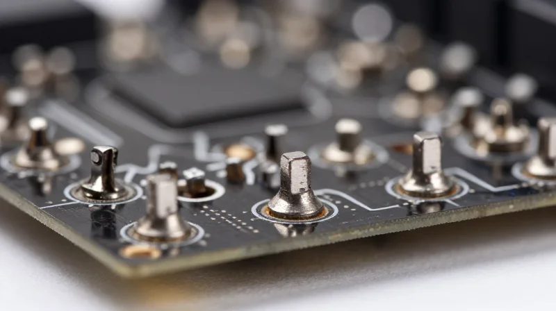
Thermal-Mechanical Stress Mitigation
TPMS sensors face extreme temperature fluctuations, ranging from -40°C to +125°C. To mitigate solder joint fatigue, place high-mass components away from corners and board edges, where mechanical stress concentration is highest. Utilizing non-solder mask defined (NSMD) pads for small components can improve thermal cycling resistance by allowing solder fillets to wrap around the pad edges, increasing overall interconnect compliance.
Optimizing Layout for Thermal Uniformity
| Placement Metric | Recommended Practice | Impact on Reliability |
|---|---|---|
| Component Orientation | Parallel to PCB stress axis | Reduces shear force on solder joints |
| Heavy IC Placement | Centrally located | Minimizes bending moments during vibration |
| Thermal Vias | Arrayed under ground planes | Prevents localized hotspots and thermal fatigue |
DFM Best Practices for Joint Integrity
- Why should high-density components be avoided near mounting holes?
Mounting holes are stress focal points; components placed in close proximity are susceptible to solder joint cracking during mechanical shock and PCB warping. - How does surface finish selection influence fatigue?
ENIG (Electroless Nickel Immersion Gold) provides superior flatness for fine-pitch parts, but HASL or OSP often provide better solder joint ductility in high-vibration environments. - Should underfill be used for BGA components?
Yes, for TPMS applications where the sensor experiences rapid G-force changes, capillary underfill is recommended to redistribute mechanical stress away from the solder balls to the package body.
Surface Finish Reliability for Long-Term Connectivity
Surface Finish Reliability for Long-Term Connectivity
Tire pressure monitoring system (TPMS) sensors operate in extreme environments characterized by high humidity, chemical exposure, and constant thermal cycling. The surface finish chosen for the PCB must protect underlying copper traces from oxidative degradation while ensuring robust intermetallic compound (IMC) formation during soldering. Failure to select the appropriate finish leads to brittle solder joints or localized corrosion, both of which are catastrophic for long-term automotive reliability.
Comparison of High-Reliability Finishes
| Feature | ENIG | ENEPIG |
|---|---|---|
| Corrosion Resistance | Moderate | Excellent |
| Thermal Shock Resilience | Moderate | Superior |
| Black Pad Risk | Higher | Minimal |
| Cost | Lower | Higher |
While Electroless Nickel Immersion Gold (ENIG) has historically been a standard, Electroless Nickel Electroless Palladium Immersion Gold (ENEPIG) is increasingly required for automotive-grade sensors. The addition of a palladium layer in ENEPIG serves as a diffusion barrier, significantly mitigating the risk of 'Black Pad' defects—a fracture-prone interface caused by phosphorus-rich nickel corrosion.
Frequently Asked Questions on Surface Finish Selection
- Why is ENEPIG preferred over ENIG for TPMS applications?
ENEPIG offers superior protection against solder joint embrittlement and corrosion, ensuring that the connection remains intact throughout the lifespan of the vehicle despite aggressive environmental exposure. - How does surface finish impact shelf-life in high-moisture environments?
Advanced finishes like ENEPIG provide better solderability after prolonged storage compared to traditional ENIG, reducing the risk of non-wetting or cold joints during final assembly if the boards have been subjected to fluctuating environmental conditions. - Does the palladium layer affect signal integrity?
At the frequencies typically used for TPMS (e.g., 315MHz or 433MHz), the thin palladium layer in ENEPIG has a negligible impact on high-frequency signal propagation compared to ENIG.
DFM Checklist for Streamlined Manufacturing

DFM Checklist for TPMS PCB Production
Before transitioning from design to manufacturing, engineers must validate the following critical parameters to mitigate risks associated with high-vibration, high-heat automotive environments.
| Category | Design Constraint | Reliability Impact |
|---|---|---|
| Stack-up | Balanced Copper Weights | Prevents board warping during thermal cycling |
| Soldering | Solder Mask Defined Pads | Enhances structural integrity of BGA connections |
| Clearance | 3x Trace Width Spacing | Reduces impedance discontinuities in HF sensors |
| Drilling | 1:10 Aspect Ratio | Ensures reliable plating in high-aspect-ratio vias |
Critical DFM Verification Questions
- Thermal Management
Are thermal vias placed directly under power-dissipating components to prevent localized overheating in the tire valve assembly? - Stress Mitigation
Have all component packages with large footprints been positioned to align with the primary axes of chassis vibration? - Surface Finish Integrity
Has ENEPIG been specified instead of standard ENIG to avoid black pad syndrome and ensure long-term intermetallic bond stability? - Environmental Protection
Is the PCB layout optimized for conformal coating coverage, including adequate keep-out zones around sensitive sensor pressure ports?
Final sign-off must include a comprehensive DFM audit report comparing the actual design file constraints against these thresholds to guarantee survivability over a 10-year vehicle lifecycle.
By strictly adhering to these DFM best practices, engineers can mitigate common failure modes and ensure their TPMS designs survive the rigors of the road. Contact our engineering team today to review your current PCB stack-up and optimize your production yields for maximum field reliability.
