
The automotive industry is undergoing a digital transformation, and tire pressure monitoring systems (TPMS) are at the forefront of this shift. As modern vehicles transition toward autonomy and V2X connectivity, the demand for high-reliability sensor data is greater than ever, rendering legacy PCB designs obsolete. This article examines the technological leaps in PCB manufacturing that are defining the next era of vehicle safety.
The Evolution of TPMS: From Basic Alerts to Data-Rich Insights
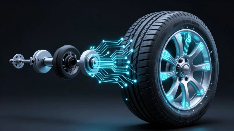
The Genesis of TPMS: Simple Safety Alerts
Early TPMS implementations were born out of a necessity to prevent catastrophic tire failure rather than optimizing vehicle performance. These legacy systems, often relying on indirect measurement techniques, tracked wheel rotation speeds via ABS sensors to infer pressure deviations. While effective for basic safety, these systems offered zero granular data, providing only a binary 'alert' notification that left drivers guessing the specific cause of the warning.
Technological Leap: The Shift to Direct Sensing and Advanced PCBs
Modern TPMS has evolved into an active, data-rich telemetry system. By integrating high-precision micro-electromechanical systems (MEMS) onto compact, robust printed circuit boards (PCBs), manufacturers can now monitor internal air temperature, pressure, and tire load in real-time. This transition from passive alerts to active monitoring is a direct result of miniaturized PCB technology, which allows for deeper integration into the vehicle’s Controller Area Network (CAN).
| Feature | Legacy Systems | Next-Gen PCB Solutions |
|---|---|---|
| Measurement Method | Indirect (ABS-based) | Direct (In-tire MEMS) |
| Data Granularity | Binary Warning | Real-time Telemetry |
| Connectivity | Standalone | Integrated CAN/IoT |
| Hardware Footprint | High (Sensor/Module) | Low (Integrated PCB) |
Frequently Asked Questions
- Why is PCB technology critical for next-gen TPMS?
Advanced PCBs allow for the consolidation of multiple sensors, signal processing units, and wireless transmitters into a single, durable package that can withstand the extreme rotational forces of a wheel. - How does this evolution benefit fleet management?
Beyond simple safety, real-time data allows for predictive maintenance, tire life extension, and fuel efficiency optimization through constant pressure and temperature monitoring.
Limitations of Legacy TPMS Sensor PCB Designs
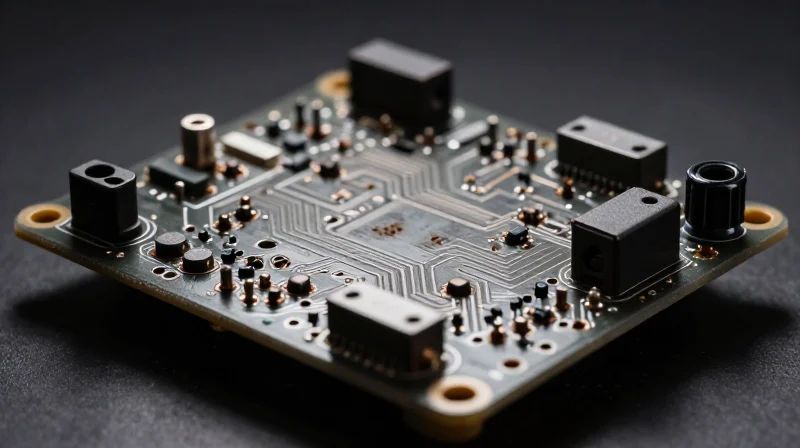
Inherent Constraints in Traditional TPMS Architectures
Traditional TPMS PCB designs were engineered primarily for simplicity and longevity, focusing on low-power consumption for long battery life. However, these older designs often rely on rigid, standard FR-4 materials and bulky component placement that struggle to accommodate the rapid miniaturization and high-frequency data requirements of modern connected vehicle ecosystems. These limitations fundamentally inhibit the system's ability to handle high-bandwidth sensor fusion or extreme thermal cycling.
Performance Bottlenecks Comparison
| Constraint Area | Legacy Design Limitation | Performance Impact |
|---|---|---|
| Thermal Management | Poor heat dissipation in dense layouts | Premature component failure under extreme road temperatures |
| Signal Integrity | Susceptibility to electromagnetic interference | Data loss or corruption during high-speed transmission |
| Structural Integrity | Rigid substrate stress concentration | Solder joint fatigue due to wheel rotation-induced vibration |
Frequently Asked Questions Regarding Legacy Limitations
- Why do legacy PCB substrates fail under high vibration?
Traditional substrates lack the mechanical flexibility to dampen energy from constant road shocks, leading to micro-fractures in solder joints over time. - How does EMI affect legacy TPMS accuracy?
Older designs often lack comprehensive shielding and optimized trace routing, making them highly susceptible to interference from other vehicle electronics, which can mask critical low-pressure alerts. - Can legacy designs support Over-the-Air (OTA) updates?
No; most legacy PCBs lack the non-volatile memory density and the necessary processing overhead required to handle secure, complex firmware updates remotely.
Material Science Innovations: High-Tg Laminates and Beyond

The Necessity of High-Tg Materials in TPMS
As Tire Pressure Monitoring System (TPMS) sensors migrate from simple rim-mounted indicators to sophisticated data nodes, the demand for superior substrate materials has reached a critical inflection point. Standard FR-4 laminates, while cost-effective for consumer electronics, often succumb to mechanical fatigue when subjected to the high-vibration, high-heat environment of a spinning wheel. High Glass Transition Temperature (Tg) laminates (typically >170°C) provide the dimensional stability and chemical resistance required to prevent delamination and solder joint failure during the rapid, extreme temperature fluctuations characteristic of automotive tire performance.
Comparative Analysis: Legacy vs. Next-Gen Substrates
| Feature | Legacy FR-4 | High-Tg Laminate |
|---|---|---|
| Glass Transition (Tg) | 130°C - 140°C | 170°C - 185°C |
| Thermal Expansion (CTE) | High (Unstable) | Low (Controlled) |
| Vibration Resilience | Moderate/Low | Exceptional |
| Moisture Absorption | Higher | Low |
Beyond Laminates: Advancing PCB Architecture
Material science innovation extends beyond the choice of resin systems. The integration of advanced metallic cores and flexible ceramic-filled laminates allows for better heat dissipation away from the sensor's microcontroller. By managing the thermal mass more effectively, manufacturers are successfully reducing the mechanical stress exerted on the copper traces, which remains the leading cause of field failures in legacy automotive sensor designs.
- Why is Tg significant for tire sensors?
The Glass Transition temperature represents the point where a polymer transitions from a rigid state to a rubbery state; exceeding this value causes expansion and potential circuit breakage. - How do these materials improve signal integrity?
By maintaining stable dielectric constants through varied temperatures, High-Tg laminates prevent signal drift in the high-frequency wireless transmissions required for real-time TPMS data. - Are there limitations to High-Tg adoption?
The primary barrier remains the cost of specialized resin systems and the requirement for optimized reflow profiles during the assembly process to accommodate higher processing temperatures.
Miniaturization and HDI Integration Trends
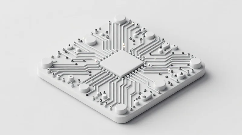
The Role of HDI in Next-Generation TPMS
As automotive safety standards evolve, the demand for more sophisticated sensor data—including temperature, pressure, and tire wear analytics—requires a departure from legacy PCB architectures. High-Density Interconnect (HDI) technology facilitates this by utilizing micro-vias, thinner traces, and improved layer stack-ups. These advancements allow manufacturers to consolidate multi-functional ICs into the tight confines of a wheel-mounted sensor housing while maintaining high signal integrity.
Structural Advantages of HDI vs. Legacy Manufacturing
| Feature | Legacy PCB | HDI Technology |
|---|---|---|
| Via Technology | Thru-hole (Drilled) | Laser-drilled Micro-vias |
| Trace Density | Low/Moderate | Ultra-High |
| Component Pitch | Coarse (>0.5mm) | Fine (<0.4mm) |
| Signal Integrity | Susceptible to crosstalk | Superior shielding and short paths |
Integration Trends and Efficiency
The transition to HDI is not merely about physical size reduction; it is about performance density. By reducing the distance between components, engineers can minimize electromagnetic interference (EMI) and power loss. This is critical for battery-operated TPMS units, where energy efficiency directly correlates to the lifespan of the sensor in harsh, high-vibration conditions.
- How does HDI improve signal reliability?
HDI allows for shorter conductive paths and sophisticated ground planes, which reduce noise and prevent signal degradation during high-frequency data transmission. - Does miniaturization compromise thermal dissipation?
While component density increases, modern HDI designs incorporate micro-vias that act as thermal conduits, effectively pulling heat away from critical power management ICs. - Why is HDI essential for future autonomous vehicle sensors?
Autonomous systems require real-time, ultra-low latency data. HDI boards provide the necessary interconnect density to house the advanced processors required for edge computing within the sensor itself.
Improving Signal Integrity in Wireless Sensor Architectures
Mitigating Electromagnetic Interference in Tire Environments
Modern automotive environments are electrically noisy, with rotating wheels creating unique challenges for signal propagation. In next-gen TPMS (Tire Pressure Monitoring Systems), maintaining a high signal-to-noise ratio necessitates advanced layout strategies, such as optimized ground plane stitching and differential pair routing, to shield sensitive sensor data from RF interference generated by vehicle braking systems and high-current actuators.
Design Strategies for Signal Robustness
| Constraint | Legacy Approach | Next-Gen PCB Solution |
|---|---|---|
| Grounding | Single-point or shared | Multi-layer stitching vias |
| Trace Routing | Standard parallel paths | Controlled impedance differential pairs |
| RF Isolation | Simple physical spacing | Integrated Faraday cage shielding |
Frequently Asked Questions on Signal Integrity
- Why is impedance control critical in tire-mounted sensors?
Precise impedance control minimizes signal reflections, ensuring that the low-power wireless packets from the TPMS sensor reach the vehicle's central ECU without attenuation despite rotation-induced stress. - How does HDI integration impact noise susceptibility?
HDI allows for shorter trace lengths and optimized via placement, which significantly reduces parasitic inductance—the primary driver of EMI-related signal degradation in compact sensor boards. - Can material choice influence signal clarity?
Yes, utilizing materials with low dissipation factors (Df) ensures minimal energy loss at high frequencies, effectively maintaining signal integrity throughout the lifespan of the PCB under harsh environmental cycling.
Thermal Management for Next-Gen Sensor Reliability
The Thermal Challenge in Compact TPMS Architectures
As TPMS sensors transition toward High-Density Interconnect (HDI) PCBs and miniaturized form factors, power density increases significantly. This miniaturization reduces the physical surface area available for convective cooling, necessitating a transition from legacy air-cooled designs to sophisticated conductive thermal management strategies.
Comparison of Thermal Dissipation Strategies
| Strategy | Legacy Approach | Next-Gen PCB Approach |
|---|---|---|
| Heat Sink Method | Passive metal enclosures | Thermal vias/PCB ground planes |
| Dielectric Material | Standard FR4 | High-Tg ceramic/Metal-core PCBs |
| Thermal Interface | Thick thermal grease | Phase-change materials (PCM) |
Material Innovation for Extreme Environments
Modern automotive sensor reliability is heavily dictated by the thermal coefficient of expansion (TCE) matching between the substrate and active components. Utilizing Metal Core Printed Circuit Boards (MCPCBs) allows for localized heat spreading, which draws energy away from the micro-controller and wireless transmitter, preventing premature degradation during high-speed highway operation or extreme solar loading.
- How do thermal vias improve PCB reliability?
Thermal vias act as vertical heat pipes, connecting the component junction to internal copper planes, effectively distributing localized heat across the entire board surface area. - Why is Tg (Glass Transition Temperature) critical?
A higher Tg ensures the substrate remains mechanically rigid at extreme temperatures, preventing solder joint fatigue and delamination during rapid thermal cycling. - Does miniaturization inherently increase failure rates?
Not necessarily; while miniaturization increases power density, next-gen substrate materials and optimized trace routing compensate by providing more efficient thermal pathways compared to bulky legacy designs.
Manufacturing Standards and Quality Assurance
Manufacturing Standards and Quality Assurance
The transition from legacy sensor architectures to next-gen PCB solutions demands a fundamental shift in quality control paradigms. Automotive tier-one suppliers must now validate compact, high-density assemblies against harsher vibration, thermal cycling, and electromagnetic interference profiles than those required for traditional through-hole components.
Core Certification and Compliance Frameworks
Quality assurance for modern TPMS electronics is governed by a strict hierarchy of automotive standards. Beyond standard manufacturing certifications, specialized testing protocols ensure that advanced PCB substrates maintain structural integrity throughout the vehicle's lifespan.
| Standard | Primary Focus | Relevance to TPMS PCB |
|---|---|---|
| IATF 16949 | Quality Management Systems | Mandatory framework for continuous process improvement. |
| AEC-Q100 | Integrated Circuit Reliability | Stress testing for silicon longevity in extreme environments. |
| IPC-A-600 | PCB Acceptability | Critical criteria for high-density interconnect (HDI) layer integrity. |
Validating Next-Gen Reliability
- How does HDI integration affect validation?
Smaller trace widths in HDI PCBs require advanced Automated Optical Inspection (AOI) and X-ray laminography to detect microscopic fractures that traditional visual checks miss. - Why is thermal cycling critical for TPMS?
Sensors mounted inside tires endure rapid temperature swings; therefore, solder joint fatigue must be mitigated through specific alloy selection and CTE (Coefficient of Thermal Expansion) matching. - What role does ISO 26262 play?
It defines the Functional Safety requirements, ensuring that in the event of a sensor board failure, the system provides a predictable and safe diagnostic state to the vehicle gateway.
The Impact on Autonomous and Connected Vehicle Safety
The Role of High-Fidelity Data in Autonomous Decision-Making
Autonomous and connected vehicles rely on a continuous stream of environmental and mechanical data to maintain safe operation. Unlike legacy TPMS solutions, which often prioritize battery longevity over transmission frequency, next-gen PCB-based sensors offer high-resolution, low-latency telemetry. This shift is essential for Advanced Driver Assistance Systems (ADAS) that must calculate vehicle dynamics—such as braking distance, handling precision, and stability control—in milliseconds.
Comparison of Sensor Integration Impact
| Performance Metric | Legacy Automotive Sensors | Next-Gen PCB TPMS |
|---|---|---|
| Data Latency | High (Multi-second lag) | Ultra-low (Sub-millisecond) |
| Signal Robustness | Susceptible to interference | High-integrity, shielded circuits |
| ADAS Integration | Limited to basic alerts | Deep integration with vehicle dynamics |
| Failure Prediction | Reactive reporting | Predictive diagnostic modeling |
Enhancing Safety through Predictive Analytics
The transition to advanced PCB designs allows for the integration of intelligent on-board processing. By moving from simple threshold monitoring to complex data analysis at the tire level, these next-gen systems can predict structural integrity issues before they cause failure. For an autonomous fleet, this capability transforms a passive safety feature into an active preventive maintenance tool that significantly reduces road incidents caused by tire blowouts or irregular pressure distributions.
- How does PCB design influence ADAS responsiveness?
Modern PCBs reduce trace resistance and electromagnetic interference, ensuring that vital tire data reaches the central vehicle computer without packet loss or jitter, allowing ADAS algorithms to react instantaneously to tire irregularities. - Why is the transition from legacy systems necessary for autonomy?
Legacy sensors lack the computational bandwidth to support the V2X communication standards and real-time vehicle stability protocols required for Level 4 and Level 5 autonomous driving. - Can these sensors mitigate weather-related safety risks?
Yes, enhanced thermal and humidity monitoring embedded within advanced PCB architectures allows the vehicle to adjust traction control and autonomous braking parameters dynamically based on current road and tire surface conditions.
The transition to next-generation PCB architectures is essential for meeting the safety demands of modern, intelligent vehicles. By embracing advanced materials and high-density designs, manufacturers can ensure greater reliability and connectivity on the road. Contact our engineering team today to discuss how we can help upgrade your automotive sensor projects to meet industry-leading performance standards.
