
In the rapidly evolving landscape of autonomous driving, the reliability of LiDAR sensors often hinges on the quality of their PCB interconnects. As systems demand smaller footprints and higher signal integrity, rigid-flex technology has become the industry standard—but choosing the wrong manufacturing partner can lead to catastrophic hardware failure. This guide empowers engineers and procurement leads to make data-driven decisions that ensure performance under the most extreme automotive conditions.
The Crucial Role of PCB Reliability in LiDAR Systems

In the evolution of autonomous driving and precision robotics, LiDAR sensors represent one of the most demanding applications for printed circuit board technology. Because these sensors must capture high-resolution spatial data in real-time, the underlying circuitry must maintain signal integrity under significant thermal stress and mechanical vibration. Rigid-flex PCB architectures have emerged as the standard solution, offering the necessary density to house complex processing units while providing the mechanical flexibility required to fit into compact, aerodynamic LiDAR housings.
Why Rigid-Flex is Essential for LiDAR Integration
LiDAR systems often involve moving parts or tight spatial constraints that make traditional rigid boards impractical. By utilizing rigid-flex circuits, designers can eliminate unreliable interconnects and cables that often serve as points of failure. This integration reduces the overall mass of the sensor, lowers impedance mismatch risks, and improves overall reliability in harsh outdoor environments.
| Feature | Traditional Rigid PCB | Rigid-Flex PCB |
|---|---|---|
| Mechanical Reliability | Low (Connector fatigue) | High (Stress distribution) |
| Signal Integrity | Variable | Excellent (No intermediate connectors) |
| Spatial Efficiency | Limited | High (3D form factor) |
Key Considerations for Reliability
- How does vibration affect LiDAR PCBs?
Constant vibrations in vehicular environments can crack solder joints on rigid boards; rigid-flex circuits distribute this mechanical stress more uniformly across flexible sections. - Why is thermal management critical for LiDAR?
LiDAR modules generate intense heat during high-speed data processing; a reliable PCB must use materials with stable coefficients of thermal expansion (CTE) to prevent delamination. - What role does signal integrity play?
High-frequency signals required for LiDAR point-cloud generation demand precision impedance control that is best achieved through integrated, solder-less rigid-flex transitions.
Evaluating Material Thermal Stability for Autonomous Environments

Managing Thermal Cycling and Coefficient of Thermal Expansion (CTE)
Autonomous LiDAR sensors operate in punishing thermal environments, ranging from sub-zero winter temperatures to blistering heat trapped under a vehicle's chassis or roof-line. In rigid-flex designs, the mismatch in Coefficient of Thermal Expansion (CTE) between the rigid FR-4 sections and the flexible polyimide layers is the primary driver of interconnect failure. A qualified manufacturer must prioritize materials that demonstrate high Glass Transition Temperatures (Tg) and low Z-axis expansion to prevent micro-via cracking and delamination during repetitive thermal cycling.
Comparative Analysis of Common Substrate Materials
| Material Type | Tg (°C) | Thermal Reliability | Best Use Case |
|---|---|---|---|
| Standard Polyimide | 200-250 | High | General flex-circuits |
| High-Tg FR-4 | 170-180 | Moderate | Standard rigid sections |
| Ceramic-Filled PTFE | 280+ | Excellent | High-frequency LiDAR RF signal integrity |
Evaluating Manufacturer Competence
- Do you provide thermal stress testing results for rigid-flex transitions?
A high-performance manufacturer should perform IPC-TM-650 thermal shock testing to validate the integrity of plated through-holes at the interface where the rigid and flexible layers meet. - How do you manage adhesive systems in the layup?
Adhesiveless polyimide laminates are preferred for LiDAR applications as they offer better thermal stability and thinner profiles compared to acrylic or epoxy-based adhesive systems. - Can your manufacturing process accommodate controlled Z-axis expansion?
Ask specifically about their lamination cycles; controlled press cycles ensure that the CTE remains uniform across the entire assembly, reducing mechanical stress on critical sensor components.
Mastering Impedance Control and Signal Integrity

Precision Impedance Control for High-Speed LiDAR Data
LiDAR systems generate massive streams of raw point-cloud data that must be transmitted across the PCB without degradation. Manufacturers must demonstrate mastery over dielectric constant (Dk) stability and precise copper geometry to maintain target impedance—typically 50Ω single-ended or 100Ω differential—within a tolerance of ±5%. Failure to control these parameters in the flexible sections of a rigid-flex board often leads to signal reflections, increased bit error rates, and potential system-level timing failures.
Key Metrics for Impedance Performance
| Metric | Requirement | Impact on LiDAR Performance |
|---|---|---|
| Impedance Tolerance | ±5% | Minimizes signal reflections in high-frequency LVDS/MIPI lines. |
| Dk Uniformity | <0.02 variation | Ensures consistent velocity of propagation across flex layers. |
| Copper Profile | Low-profile/VLP | Reduces skin effect losses at high frequencies. |
Maintaining Signal Integrity Through Flex-Rigid Transitions
The transition from rigid FR-4 to flexible polyimide introduces significant mechanical and electrical discontinuities. High-performance LiDAR integration demands manufacturers who utilize advanced drilling and plating techniques to ensure copper continuity through the z-axis transition. Furthermore, the design of ground planes across these interfaces must be carefully managed to prevent impedance 'bumps' that act as antennas, radiating EMI and interfering with the sensitive photodetector arrays within the LiDAR unit.
Frequently Asked Questions on Signal Integrity
- How does coverlay choice affect signal performance?
Coverlay thickness and dielectric material properties directly influence effective impedance. Selecting a manufacturer with a broad library of pre-qualified adhesive and coverlay combinations is essential for precise modeling. - Why is Time Domain Reflectometry (TDR) testing non-negotiable?
TDR testing provides a real-time visual map of impedance discontinuities. Any manufacturer producing rigid-flex for LiDAR should perform 100% coupon testing to verify that designs meet the calculated impedance profile. - Can flexible circuits handle high-speed differential pairs?
Yes, provided the manufacturer employs balanced copper routing and maintains precise spacing control in the flex area to keep differential pairs coupled tightly throughout the entire signal path.
Navigating Automotive Certification: ISO 9001 and IATF 16949
Quality Standards as a Foundation for Reliability
For LiDAR sensor integration, certification is not merely a bureaucratic hurdle; it is a vital indicator of a manufacturer's process control capabilities. When rigid-flex circuits are deployed in autonomous driving systems, failure is not an option. ISO 9001 serves as the baseline for management systems, while IATF 16949 provides the rigorous, automotive-specific framework necessary to ensure consistency across high-volume, mission-critical production runs.
Comparing Quality Frameworks
| Certification | Focus Area | Relevance to LiDAR |
|---|---|---|
| ISO 9001 | General Quality Management | Ensures basic document control and operational efficiency. |
| IATF 16949 | Automotive Supply Chain | Requires defect prevention, waste reduction, and rigorous traceability. |
Key Considerations for Certification Auditing
- Why is IATF 16949 specifically required for LiDAR PCBs?
Unlike consumer electronics standards, IATF 16949 mandates advanced product quality planning (APQP) and production part approval processes (PPAP), which are critical for validating the reliability of complex rigid-flex assemblies in vehicle environments. - What does a manufacturer's 'Automotive Scope' imply?
A facility may hold general ISO certification but lack the specific automotive-accredited scope. Always verify that their certification covers the manufacturing of printed circuit boards for automotive end-use to ensure adherence to Tier 1 OEM requirements. - How does certification impact long-term supply chain security?
Certified manufacturers utilize standardized corrective action protocols (8D reports), which minimize the risk of prolonged downtime during production scaling or in the event of unforeseen component anomalies.
Selecting a partner with deep automotive certification expertise minimizes design-to-production risk. Ensure that your PCB partner can provide documented evidence of their compliance and demonstrate how these standards integrate into their specific rigid-flex fabrication workflow, particularly concerning multi-layer registration and thermal cycling testing.
Manufacturing Capability Assessments: Beyond the Spec Sheet
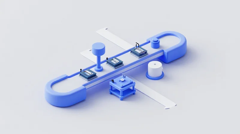
A spec sheet confirms what a facility can theoretically achieve, but manufacturing capability assessments reveal what they can reliably deliver. For LiDAR integration, where complex rigid-flex designs must survive extreme automotive environments, a manufacturer's true value lies in their proactive design-for-manufacturing (DFM) feedback and their proficiency in handling high-density, multi-layer interconnects without compromising structural integrity.
Evaluating DFM Competency: The Proactive Partnership
The strongest indicator of a capable partner is their willingness to challenge your design before it reaches production. True DFM expertise involves identifying potential stress concentration points in the flex zones, optimizing copper weight distribution to prevent cracking during thermal cycling, and ensuring that component placement does not inhibit the flexibility required for final assembly. A partner that merely accepts your Gerber files without questions is a liability; a partner that suggests adjustments to via-in-pad geometry or bend radius constraints is an asset.
Capacity for Complexity: Layer Counts and Materials
| Feature | Baseline Capability | Advanced LiDAR Integration |
|---|---|---|
| Max Layer Count | 6-8 Layers | 12-24+ Layers |
| Registration | Standard tolerance | Ultra-fine (laser direct imaging) |
| Flex Material | Polyimide | Low-loss, high-T g variants |
| Via Technology | Mechanical drilling | Stacked/Staggered micro-vias |
Critical Manufacturing Assessment FAQ
- How do I verify a manufacturer's capacity for high-density interconnects?
Request their process capability report for aspect ratio limitations in high-layer-count boards and ask for evidence of their experience with laser-drilled micro-vias in sequential lamination processes. - Does the manufacturer's equipment list matter more than their process flow?
Equipment is necessary, but the process flow—how they handle the flex-to-rigid transition and chemical bonding—is the differentiator for reliability in high-vibration automotive environments. - What is the biggest risk when scaling from prototyping to high-volume LiDAR production?
The transition often exposes inconsistencies in material handling and registration drift across large-format panels; verify their use of automated optical inspection (AOI) specifically tuned for flexible circuits.
Supply Chain Transparency and Long-term Scalability
Ensuring Supply Chain Resilience and Transparency
For high-performance LiDAR integration, supply chain transparency is a prerequisite for risk mitigation. You must vet a manufacturer's material sourcing strategy, specifically focusing on their sub-tier supplier relationships for specialized polyimide films and copper foils. A reliable partner should provide full traceability reports, ensuring that the critical materials used in your prototype match those in high-volume production, preventing sudden quality drifts that could jeopardize automotive safety standards.
Scalability: From Prototype to Mass Production
Scaling rigid-flex manufacturing requires more than just machine capacity; it demands a transition from manual assembly processes to automated, high-precision fabrication lines. Before committing, confirm that the manufacturer can replicate the exact processing environment of your successful prototype at a significantly larger scale without introducing new impedance or mechanical tolerances.
| Evaluation Criterion | Prototype Phase Focus | Mass Production Focus |
|---|---|---|
| Material Sourcing | Performance validation | Supply chain stability |
| Production Setup | Flexible iteration | Process repeatability |
| Lead Times | Accelerated delivery | Predictable scheduling |
Frequently Asked Questions on Manufacturing Scalability
- How do I ensure material consistency during scaling?
Require a locked Bill of Materials (BOM) and documented evidence of consistent material certification from their suppliers to prevent unauthorized substitutions during high-volume runs. - Does the manufacturer have disaster recovery plans?
A high-performance partner should demonstrate contingency plans for supply chain disruptions, including multi-sourcing strategies for critical laminate materials and secondary manufacturing facilities. - Why does production location matter for LiDAR?
Proximity to assembly clusters often reduces logistics risks, but more importantly, it allows for tighter integration and communication between your engineering team and the factory floor during the ramp-up phase.
Quality Assurance Testing Protocols for Sensor Reliability
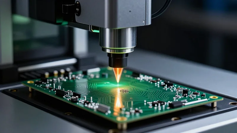
For LiDAR applications, where sensor failure can result in system-level catastrophe, manufacturers must move beyond standard functional testing. Reliability is built through destructive and non-destructive analysis protocols that validate the integrity of the rigid-flex interconnect under harsh environmental and mechanical conditions.
Essential Validation Protocols
- Cross-Sectional Analysis
Micro-sectioning is used to inspect via barrel integrity, plating thickness, and layer registration, ensuring the copper plating in the transition zone between rigid and flex sections can withstand thermal expansion cycles. - Environmental Stress Screening (ESS)
Subjecting boards to rapid thermal cycling and vibration profiles mimicking automotive environments identifies hidden defects, such as trace micro-cracks or solder joint fatigue, before integration. - Flight-Testing and Field Validation
This involves rigorous real-world data collection, verifying that the electrical signal integrity of the PCB remains stable during high-velocity data acquisition and fluctuating electromagnetic interference.
Comparative Analysis of Reliability Testing
| Testing Protocol | Primary Objective | Failure Mode Detected |
|---|---|---|
| Micro-sectioning | Material Integrity | Plating Voids / Delamination |
| Thermal Cycling | Joint Reliability | Solder Fatigue / Trace Cracking |
| X-Ray Inspection | Layer Alignment | Internal Shorts / Misregistration |
Best Practices for Manufacturer Auditing
When selecting a partner, demand documentation of their 'First Pass Yield' for high-layer count rigid-flex designs. A reliable manufacturer will readily provide detailed failure mode and effects analysis (FMEA) reports. If a supplier cannot provide evidence of long-term reliability testing specific to dynamic flex cycles, they are likely unsuitable for high-performance automotive LiDAR applications.
Communication and Technical Support as a Partnership Metric
The Role of Collaborative Design Reviews in the NPI Process
In the fast-paced development of high-performance LiDAR systems, the New Product Introduction (NPI) phase is often where costly bottlenecks occur. A manufacturer that treats communication as a partnership metric rather than a transactional necessity will implement structured design reviews. These reviews are not mere checklists; they are collaborative engagements where the manufacturer’s DFM engineers work directly with your design team to identify potential signal integrity issues, flex fatigue points, or mechanical assembly constraints before a single board is fabricated.
Responsive Support: Translating Technical Issues into Solutions
Selecting a partner requires assessing how they handle unforeseen technical hurdles. When a production anomaly arises, a partner with superior technical support provides immediate, data-driven root cause analysis rather than automated status updates. This responsiveness minimizes downtime during critical sensor calibration cycles.
| Communication Metric | Reactive Manufacturer | Partnership-Oriented Manufacturer |
|---|---|---|
| Design Review Feedback | Pass/Fail reporting only | Iterative suggestions for yield optimization |
| Issue Escalation | General support ticketing | Direct access to DFM/Process engineers |
| Technical Transparency | Siloed manufacturing data | Real-time visibility into production stressors |
Frequently Asked Questions on Manufacturer Engagement
- Why is direct engineer-to-engineer communication critical for LiDAR?
LiDAR projects involve complex impedance and thermal management requirements that are often lost in translation when filtered through sales representatives or project managers. - How do I measure the effectiveness of a manufacturer's support team?
Monitor their response time to non-conformances and their willingness to host virtual design review sessions that address specific stack-up or material challenges. - Does early-stage technical support impact long-term scalability?
Yes, collaborative early-stage design ensures that the manufacturing process is optimized for high-volume yield, preventing costly redesigns when moving from prototype to mass production.
Selecting a PCB partner for LiDAR integration is not merely about finding a vendor; it is about securing a critical component of your vehicle's safety system. By prioritizing thermal resilience, signal integrity, and automotive-grade certification, you minimize risk and accelerate time-to-market. Are you ready to optimize your hardware for the next generation of autonomy? Contact our engineering team today for a comprehensive design review.
