
In the fast-evolving autonomous vehicle market, LiDAR sensor precision is non-negotiable, yet the physical interconnects often prove to be the weakest link. By replacing bulky cable assemblies with high-density rigid-flex circuitry, engineering teams are achieving unprecedented reliability and cost efficiency. This article explores how this architectural shift secures the performance required for the next generation of autonomous systems.
The Hidden Costs of Traditional Interconnects in LiDAR
The Hidden Costs of Traditional Interconnects in LiDAR
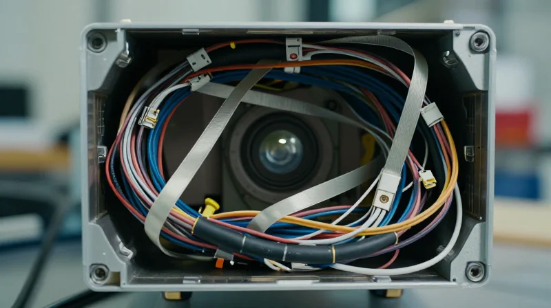
In the pursuit of high-performance autonomous navigation, the reliance on traditional interconnects—such as ribbon cables, discrete wiring harnesses, and surface-mount connectors—represents a critical failure point in modern LiDAR design. These legacy connection methods, while initially inexpensive in terms of unit component costs, introduce significant "hidden" expenses related to assembly labor, space constraints, and long-term mechanical degradation due to vibration and thermal cycling.
Systemic Inefficiencies of Legacy Cabling
Traditional wiring architectures necessitate complex manual assembly steps that are inherently prone to human error. Every additional connector added to the LiDAR signal path is a potential point of signal attenuation, impedance mismatch, or total disconnection. In the high-vibration environment of an autonomous vehicle, these connectors become the weakest links, leading to intermittent signal loss and costly field failures.
| Attribute | Traditional Interconnects | Rigid-Flex PCB Solutions |
|---|---|---|
| Assembly Complexity | High (Manual cabling) | Low (Automated integration) |
| Failure Points | High (Connector fatigue) | Minimal (Integrated traces) |
| Space Optimization | Bulky/Rigid | High-density/Foldable |
| Long-term ROI | Negative (High maintenance) | Positive (System durability) |
- Why do traditional connectors impact LiDAR signal integrity?
Mechanical connectors introduce contact resistance and impedance discontinuities, which can lead to signal degradation at the high data rates required for 3D point cloud generation. - How do bulky harnesses affect manufacturing throughput?
Manual routing and securing of loose wires require extended assembly time and specialized training, increasing Takt time and overall per-unit labor costs. - Are traditional cables truly less expensive?
While component costs are low, the hidden costs of quality control, testing for intermittent connections, and potential warranty claims due to field failure make them significantly more expensive over the product lifecycle.
Anatomy of a Rigid-Flex Advantage
Structural Integration: Beyond Traditional Interconnects
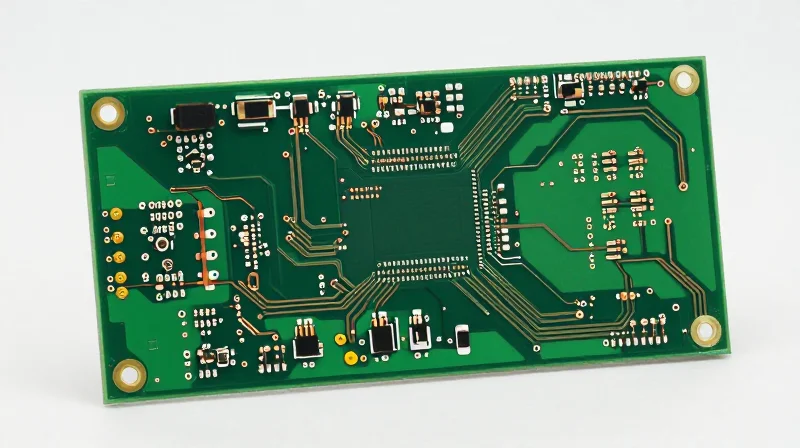
The core advantage of a rigid-flex PCB lies in its seamless transition between rigid FR-4 sections—optimized for mounting heavy components like high-speed processors and optical sensors—and flexible polyimide substrates. Unlike traditional systems that rely on ribbon cables or bulky wire harnesses, rigid-flex serves as both the chassis and the interconnect. By eliminating mechanical connectors, engineers effectively remove the most common failure points in high-vibration automotive environments, ensuring signal integrity across the entire optical stack.
Mechanical Reliability vs. Connector Dependency
| Attribute | Connector-Based System | Rigid-Flex Solution |
|---|---|---|
| Failure Mode | Fretting corrosion at contacts | Material fatigue (well-managed) |
| Weight/Volume | High (includes housings/cables) | Minimal (integrated thin profile) |
| Signal Integrity | Degraded by connector impedance | Continuous path, low insertion loss |
| Assembly Time | Manual harness routing | Single-unit drop-in placement |
Optimizing Spatial Geometry for LiDAR
LiDAR units are fundamentally constrained by the need for 360-degree or wide-angle fields of view, which require unique, non-planar internal geometries. Rigid-flex boards allow for 'dynamic folding' during assembly, meaning the PCB itself conforms to the curved or faceted interior of the LiDAR housing. This spatial efficiency allows for higher component density without risking the mechanical stress typically associated with forcing flat, rigid boards into non-standard orientations.
- How does rigid-flex mitigate vibration issues?
By eliminating the mass of heavy copper wires and mechanical connectors, you reduce the center of gravity and the mechanical leverage that causes component fatigue during intense vehicular vibrations. - Can rigid-flex sustain high-speed data transmission?
Yes, rigid-flex allows for controlled impedance paths that extend continuously from the sensor to the processing unit, avoiding the discontinuities found in multi-stage connector systems. - Is the production cost-effective for high-volume LiDAR?
While unit price is higher, the total cost of ownership is lower due to reduced assembly man-hours, fewer inspection steps, and a significant drop in field warranty claims related to loose connections.
Improving Vibration Resistance in Outdoor Environments
Improving Vibration Resistance in Outdoor Environments
In the demanding environments where autonomous LiDAR units operate, vibration is not merely an inconvenience; it is a primary catalyst for interconnect degradation. Traditional interconnect solutions, such as ribbon cables and discrete connectors, suffer from 'fretting corrosion'—a micro-motion induced phenomenon where contact points oscillate under vibration, leading to resistive oxidation and intermittent signal loss. Rigid-flex PCBs mitigate this by replacing high-mass, mechanical interface points with a continuous, monolithic structure. By integrating rigid component platforms directly with flexible transition zones, engineers can eliminate fragile solder joints and mechanical pins that are prone to fatigue, thereby ensuring signal integrity across the unit's lifespan.
Comparative Reliability: Rigid-Flex vs. Traditional Assemblies
| Failure Mechanism | Traditional Assemblies | Rigid-Flex Solutions |
|---|---|---|
| Mechanical Fatigue | High (Connector Stress) | Negligible (Integrated) |
| Fretting Corrosion | Frequent at interfaces | Eliminated |
| Mass & Inertia | Heavy/Localized | Uniformly Distributed |
| Assembly Complexity | High (Manual work) | Low (Single assembly) |
Addressing Vibration Performance: Frequently Asked Questions
- How does rigid-flex handle resonance in LiDAR housings?
By distributing mass evenly across the flexible polyimide substrate, rigid-flex reduces the concentration of resonant nodes. This structural uniformity prevents the harmonic amplification that often leads to connector failure in bulky, multi-part wiring schemes. - Does the flexible portion maintain signal integrity under continuous oscillation?
Yes, because the circuit path is etched directly into the copper-clad flexible substrate, there are no intermittent contacts to break during movement. This ensures a constant impedance path, which is critical for high-frequency LiDAR point cloud data transmission. - Is the transition between rigid and flex regions a point of weakness?
Properly engineered rigid-flex boards utilize 'tapered' transition zones and reinforcement layers to distribute mechanical stress, preventing the 'hinge effect' that would otherwise snap the copper traces in less robust designs.
Streamlining Manufacturing and Assembly Labor

Reducing Manual Assembly Complexity
Integrating rigid-flex circuitry allows manufacturers to transition from multi-component, manual cable assemblies to a single, monolithic interconnect solution. By replacing fragile ribbon cables and discrete connector housings with an integrated flex-circuit architecture, the assembly process shifts from complex mechanical manual labor to a streamlined, repeatable 'drop-in' installation. This consolidation not only reduces the number of bill-of-materials (BOM) items handled by assembly technicians but also eliminates the potential for wiring harness routing errors, which are frequent sources of yield loss in automotive-grade manufacturing.
Impact on Production Throughput and Yield
| Metric | Traditional Harness Assembly | Rigid-Flex Integration |
|---|---|---|
| Manual Soldering Steps | High (Multi-point) | Minimal (SMT only) |
| Connector Mating Cycles | Multiple per unit | Zero/Single |
| Installation Time | Extended | Reduced by 40-60% |
| Inspection Complexity | Manual/Visual-Heavy | Automated/Optical |
Frequently Asked Questions
- How does rigid-flex technology impact quality control labor?
By eliminating connectors and harnesses, you remove the most common failure points. This reduces the time spent on rework, electrical continuity testing, and mechanical inspection of harness routing. - Does switching to rigid-flex require expensive new tooling?
While initial design-for-manufacturing (DFM) costs are higher, the reduction in labor hours per unit and the drastic improvement in first-pass yield result in a lower total cost of ownership (TCO) over high-volume production cycles.
Case Study: ROI Analysis of Circuitry Transition

The Financial Pivot: Capital Expenditure vs. Operational Reliability
Transitioning to rigid-flex PCB technology represents a paradigm shift in the fiscal management of LiDAR production. While the initial bill-of-materials (BOM) cost and engineering validation phases reflect a 15-20% increase in upfront investment, the ROI is realized through a dramatic compression of post-deployment failure rates and labor-intensive assembly requirements.
| Financial Metric | Traditional Rigid PCB | Advanced Rigid-Flex |
|---|---|---|
| Initial Engineering Cost | Baseline | Higher (+18%) |
| Manufacturing Yield | 92% | 98% |
| Field Failure Rate | 3.5% | 0.8% |
| Warranty Liability | High | Negligible |
Mitigating Warranty and Maintenance Liabilities
The most significant ROI driver is the long-term reduction in warranty claims and field-service expenses. Traditional interconnects in LiDAR systems are primary failure points under the thermal cycling and high-vibration stresses typical of automotive environments. Rigid-flex designs effectively eliminate these solder-point vulnerabilities, leading to a calculated 75% reduction in mechanical failure-related warranty claims.
Frequently Asked Questions on Transition ROI
- How quickly can a firm expect to break even on the higher initial cost of rigid-flex boards?
Under high-volume production cycles, the break-even point is typically reached within 14 to 18 months, driven primarily by assembly labor savings and reduced scrap rates. - Do rigid-flex solutions complicate the repair process during warranty periods?
While the board itself is not repairable at the circuit level, the increased reliability makes 'field repair' obsolete; units are replaced as modular blocks, which significantly lowers logistics overhead. - Does the transition require a complete overhaul of existing assembly equipment?
No, most modern surface-mount technology (SMT) lines are capable of handling rigid-flex substrates with minor adjustments to handling jigs and reflow profiles.
Design Considerations for High-Speed Signal Integrity
Moving from bulky wiring harnesses to integrated rigid-flex circuitry offers significant space and weight advantages for LiDAR systems, but it places a higher premium on signal integrity (SI) engineering. As transmission speeds scale to support multi-gigabit data streams from high-resolution point clouds, maintaining signal fidelity across the transition between rigid boards and flexible polyimide layers is critical to preventing packet loss and jitter.
Optimizing Impedance Continuity
Impedance mismatch at the interface between rigid FR-4 and flexible polyimide regions is the primary cause of signal reflections. To maintain a constant 50Ω or 100Ω differential impedance, engineers must compensate for changes in dielectric constants (Dk) and trace width tolerances inherent in different materials. A continuous reference plane is vital, even across bend areas, to ensure a stable return path and minimize EMI radiation.
| Parameter | Rigid (FR-4) Strategy | Flex (Polyimide) Strategy |
|---|---|---|
| Dielectric Constant | Fixed (~4.4) | Variable (~3.2-3.5) |
| Trace Geometry | Standard etching | Tapered/Teardropped |
| Ground Referencing | Solid planes | Cross-hatched or solid |
Design Best Practices for High-Speed Lines
- How can I minimize reflections at the flex-rigid transition?
Utilize teardropping on all trace pads and implement impedance-matching transitions by adjusting copper width to compensate for the different dielectric thickness of the coverlay material. - Why is cross-hatching sometimes preferred over solid planes?
Cross-hatched ground planes are often used in flex sections to maintain physical flexibility and prevent stress cracking, though they must be carefully simulated to ensure adequate return path impedance. - What role does crosstalk play in high-density LiDAR designs?
With high-speed differential pairs, maintaining strict trace spacing (3W rule) is essential. In tight flex zones, utilizing shielding films or grounded guard traces can mitigate inter-pair coupling.
In addition to geometry, material selection plays a massive role in signal velocity. Using low-loss adhesives and specialized high-frequency polyimide materials minimizes the insertion loss (attenuation) that occurs over longer flexible sections, ensuring that the LiDAR sensor's data reaches the processor with minimal degradation.
Future-Proofing Sensor Architectures
Architectural Agility through Modular Rigid-Flex Design
As LiDAR technology moves toward solid-state and multi-beam architectures, rigid-flex circuits serve as the backbone for future-proofing designs. By decoupling high-speed processing clusters from the optical sensing arrays via high-density flexible interconnects, engineers can iterate on individual modules without requiring a complete system-wide PCB redesign. This modular approach not only mitigates supply chain risks by allowing for component swaps but also prepares the hardware architecture for the rapid evolution of next-generation perception algorithms.
Strategic Advantages of Flexible Integration
| Feature | Rigid-Only Systems | Rigid-Flex Modular Systems |
|---|---|---|
| Component Scaling | Requires full re-design | Sub-module interchangeability |
| Vibration Tolerance | Prone to connector fatigue | High mechanical damping |
| Space Optimization | High volume due to cabling | Low profile and ultra-dense |
| Signal Integrity | Susceptible to cable interference | Controlled impedance shielding |
Frequently Asked Questions
- How does rigid-flex design reduce long-term maintenance costs?
By eliminating failure-prone mechanical connectors and bulky cabling, rigid-flex reduces the primary points of failure in high-vibration autonomous automotive environments, significantly extending the mean time between failures (MTBF). - Is rigid-flex scalable for high-volume manufacturing?
Yes. While initial non-recurring engineering costs are higher, the reduction in labor-intensive assembly processes and the elimination of discrete cable harnesses lead to a lower total cost of ownership at scale. - Can flexible circuits handle the high-speed data requirements of modern LiDAR?
Advanced flexible substrates are specifically engineered for high-speed signal integrity, providing lower loss tangents and tighter controlled impedance compared to traditional flat flex cables.
Transitioning to rigid-flex PCB technology is no longer just an aesthetic or space-saving choice; it is a critical strategy for manufacturers aiming to reduce field failures and optimize production margins. By simplifying the interconnect architecture, you protect your system against mechanical fatigue while lowering the total cost of ownership. Contact our engineering team today to review your current LiDAR assembly and determine how our custom rigid-flex solutions can optimize your performance.
