
In the fast-evolving automotive landscape, Electronic Control Units (ECUs) are the nervous system of modern vehicles. As power density increases and form factors shrink, engineers face the dual challenge of extreme thermal cycling and severe mechanical vibration. This article provides a comprehensive DFM roadmap to ensure your ECU designs meet the rigorous reliability standards demanded by today’s automotive industry.
The Anatomy of Automotive-Grade Reliability
The Failure Gap: Consumer vs. Automotive Standards
The primary distinction between consumer-grade and automotive-grade PCB design lies in the operational lifecycle and environmental envelope. While consumer devices are often engineered for a 2- to 3-year lifespan in climate-controlled conditions, Electronic Control Units (ECUs) must maintain absolute reliability for 15+ years across temperature fluctuations ranging from -40°C to +125°C. Standard DFM rules fail to account for the accelerated aging caused by thermal cycling, electrolytic capacitor drying, and high-frequency vibrations common in powertrain environments.
| Parameter | Consumer Electronics | Automotive ECU |
|---|---|---|
| Design Life | 2-3 years | 15+ years |
| Thermal Range | 0°C to 40°C | -40°C to 125°C |
| Vibration Standard | Minimal | ISO 16750-3 compliance |
| MTBF Expectation | High | Ultra-high (Mission Critical) |
Critical DFM Parameters for ECU Reliability
- Why is CTE (Coefficient of Thermal Expansion) mismatch so critical?
Materials with disparate expansion rates cause solder joint fatigue and via barrel cracking during extreme thermal cycling, requiring high-Tg laminates to stabilize the PCB structure. - How does signal integrity differ for ECUs?
Automotive environments are inherently noisy; DFM rules must emphasize aggressive shielding, localized ground planes, and transient suppression to meet CISPR 25 EMC standards. - What is the role of conformal coating in DFM?
Designers must account for coating clearance and keep-out zones to ensure protection against condensation and conductive contaminants without interfering with high-speed signal pathways.
Integrating these advanced DFM protocols requires moving beyond geometric constraints to embrace materials science and mechanical survivability as core PCB design pillars. Failure to reconcile these requirements during the initial layout phase inevitably results in field failures that are significantly costlier than the upfront investment in ruggedized design practices.
Thermal Expansion Challenges and CTE Matching
Managing CTE Mismatch in High-Performance ECUs
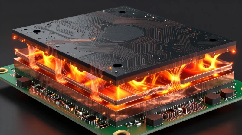
The fundamental challenge in ECU reliability is the mechanical disparity between substrate materials, copper features, and surface-mount components. As ECUs operate in environments ranging from -40°C to +125°C, disparate expansion rates create cyclic stress at the solder interface, leading to micro-cracking and eventual interconnect failure. Achieving structural integrity requires aligning the Z-axis CTE of the laminate with the components to minimize differential strain.
Strategic Material Selection and Stackup Balancing
Engineers must prioritize materials with low CTE properties, typically utilizing high-Tg (glass transition temperature) FR-4 or ceramic-filled laminates. When designing the stackup, structural symmetry is non-negotiable; unbalanced copper distribution causes the board to warp during thermal excursions, amplifying stress on BGA (Ball Grid Array) solder balls.
| Material Type | Typical CTE (ppm/°C) | Automotive Application Suitability |
|---|---|---|
| Standard FR-4 | 14-17 | Low (High fatigue risk) |
| High-Tg/Filled Laminate | 10-13 | High (Recommended) |
| Ceramic/PTFE | 6-9 | Specialized (High-Frequency) |
FAQs on CTE and Mechanical Fatigue
- How does via-in-pad affect thermal cracking?
Via-in-pad structures concentrate thermal stress. To mitigate this, ensure the via barrel is copper-filled and capped to prevent the expansion of resin from rupturing the plating. - Why is the Z-axis CTE more critical than X-Y?
The Z-axis CTE is the primary driver of via barrel cracking, as the substrate expands significantly more than the copper plating during high-temperature cycles, stretching the metal beyond its elastic limit. - Can solder alloy selection mitigate CTE stress?
Yes, utilizing high-ductility alloys or compliant solder paste formulations can absorb a portion of the mechanical strain, though PCB material selection remains the primary defense.
Advanced Thermal Management Techniques
Advanced Thermal Management Techniques
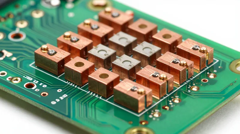
Effective thermal management in automotive ECUs requires a multi-dimensional approach that balances electrical signal integrity with aggressive heat dissipation. Because modern ECUs operate in high-ambient temperature environments with significant power densities, designers must transcend standard thermal relief patterns by integrating high-conductivity materials and optimized structural geometry.
Strategic Thermal Via Engineering
Thermal vias serve as the primary conduit for heat transfer from component junctions to inner layer planes. To maximize efficiency, designers should implement capped and plated-through hole (PTH) arrays with precise pitch control. Avoid standard daisy-chain patterns in favor of staggered grids that reduce mechanical stress on the PCB substrate while ensuring maximum copper-to-dielectric thermal contact.
| Technique | Primary Benefit | DFM Consideration |
|---|---|---|
| Capped/Filled Vias | Minimized voiding | Requires secondary plating |
| Heavy Copper Pours | Low thermal resistance | Impacts etching tolerances |
| High-Tg Substrates | Structural integrity | Increased material cost |
Comparative Analysis of Thermal Materials
- How do heavy copper pours affect impedance?
While heavy copper (2oz+) improves thermal mass, it significantly alters line width/gap calculations, requiring a re-simulation of signal integrity protocols to maintain controlled impedance. - When should metal-core PCBs be used?
Metal-core substrates are recommended for high-power LED drivers or motor control modules where heat flux exceeds the lateral dissipation capacity of standard FR-4/high-Tg resin systems. - Is via plugging mandatory?
In automotive applications, yes. Via plugging prevents solder wicking into the via barrel during reflow, which ensures a consistent thermal path and prevents potential reliability failures caused by internal voids.
Code Implementation for Thermal Constraints
/* Define thermal via constraints for high-power zones */
rule Thermal_Via_Array {
  pattern: STAGGERED;
  pitch: 0.8mm;
  plating: 25um_min;
  fill: CONDUCTIVE_EPOXY;
  thermal_relief: NONE;
}
Designing for Vibration and Mechanical Stress
Designing for Vibration and Mechanical Stress
Electronic Control Units (ECUs) are subject to high-frequency engine vibrations and sudden mechanical shocks that can lead to solder joint fractures, intermetallic growth, and mechanical fatigue. Effective DFM for automotive PCBs necessitates a rigid architectural approach that minimizes board deflection under stress.
Strategies for Mechanical Reinforcement
To mitigate stress concentrations, designers must prioritize component placement away from high-deflection zones and implement physical reinforcement strategies.
- Stiffener Utilization
Apply FR4 or metal stiffeners in areas of high board density to increase the effective Young's modulus of the PCB, preventing flexure-induced cracking during vehicle chassis vibration. - Mounting Hole Proximity
Ensure critical components are placed at least 5mm away from mounting holes to prevent the propagation of stress forces originating from hardware torque and structural chassis movement. - Underfill and Encapsulation
Utilize capillary underfills for large BGA components to distribute mechanical stress across the entire package underside, significantly enhancing solder joint longevity.
| Technique | Primary Benefit | Best Application |
|---|---|---|
| Corner Bonding | Resists solder fatigue | Large BGA/QFN packages |
| Conformal Coating | Dampens micro-vibrations | Entire populated surface |
| Stiffening Ribs | Limits board deflection | Long, narrow form factors |
Shock-Absorbent Mounting Techniques
The interface between the ECU housing and the PCB is the most critical juncture for vibration energy transfer. Mechanical isolation should be the primary design objective.
- Floating Mounts
Use elastomeric dampers or rubber grommets between the PCB mounting points and the enclosure to shift the natural frequency of the board away from the primary harmonic excitation frequencies of the engine. - Controlled Deflection
Calculate the maximum allowable deflection using finite element analysis (FEA) to ensure that solder joints are never stressed beyond their elastic limit during extreme shock events.
Ensuring Signal Integrity in Harsh Environments
Mitigating Thermal-Induced Impedance Shifts
In harsh ECU environments, rapid temperature cycling causes the dielectric constant of FR-4 materials to shift, directly altering trace impedance. To maintain signal integrity, designers must transition to high-Tg, low-loss laminates that exhibit stable dielectric properties across a wider temperature range. Furthermore, incorporating impedance-controlled routing with tighter tolerances accounts for the mechanical deformation of the substrate under thermal stress.
Managing Noise and Crosstalk in High-Density Layouts
| Interference Factor | DFM Mitigation Strategy | Performance Impact |
|---|---|---|
| Electromagnetic Interference | Solid reference planes and stitching vias | Reduces EMI emissions by 15-20dB |
| Crosstalk | Increased trace-to-trace spacing (3W rule) | Lowers capacitive coupling significantly |
| Ground Bounce | Decoupling capacitor placement | Stabilizes transient supply currents |
Best Practices for Harsh Environment Signal Protocols
- How do I prevent signal degradation due to vibration?
Ensure all differential pairs are length-matched and routed on internal layers to minimize susceptibility to mechanical surface stresses that can induce micro-cracking. - Is back-drilling necessary for ECU PCBs?
Yes, for high-speed signals above 1Gbps, back-drilling unused via stubs is essential to eliminate resonant stubs that cause signal reflections and timing jitter. - How does heavy copper affect signal integrity?
While heavy copper improves thermal dissipation, it increases edge-rounding effects during etching, which can alter characteristic impedance; account for this during the PCB stack-up design phase.
Material Selection: Laminates and Surface Finishes
High-Performance Substrate Selection
For automotive ECU applications, standard FR-4 is insufficient. Engineers must specify high-Tg (Glass Transition Temperature) laminates to prevent resin decomposition and delamination when subjected to prolonged under-the-hood temperatures. For high-power density modules, metal-core PCBs (MCPCBs) or ceramic-filled laminates offer superior thermal conductivity, effectively shunting heat away from sensitive power semiconductors while maintaining structural rigidity.
| Material Type | Key Advantage | Typical Application |
|---|---|---|
| High-Tg FR-4 | Thermal stability up to 170°C+ | General logic & body controllers |
| Metal Core (MCPCB) | Excellent heat dissipation | LED drivers & high-current motor control |
| Ceramic-Filled | Low CTE, high dielectric reliability | Sensors & high-frequency RF modules |
Optimizing Surface Finishes for Harsh Environments
The choice of surface finish directly impacts the board's susceptibility to corrosion and solder joint embrittlement. In harsh automotive environments, the finish must resist chemical contaminants while providing a robust interface for SMT components.
- ENIG (Electroless Nickel Immersion Gold)
Provides excellent planarity and oxidation resistance; however, monitor for potential 'black pad' issues in high-vibration scenarios. - ENEPIG (Electroless Nickel Electroless Palladium Immersion Gold)
The gold standard for reliability; the palladium layer prevents nickel corrosion and offers superior wire bonding and soldering performance. - Immersion Silver
Cost-effective and provides good thermal cycling performance, but requires careful handling to prevent tarnishing or ionic contamination.
Design Best Practices
When finalizing laminate specifications, always prioritize materials with a low Coefficient of Thermal Expansion (CTE) that closely matches copper. This minimizes mechanical stress on vias during thermal cycling. Additionally, ensure the surface finish is compatible with the intended soldering profile, specifically avoiding finishes that promote tin-whisker growth in high-reliability mission-critical ECUs.
Optimizing Solder Joint Reliability
Refining Pad Geometry and Solder Mask Design
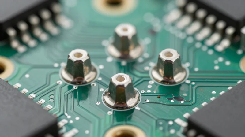
In automotive ECUs, solder joint longevity is primarily a function of fatigue resistance under thermal cycling. Pad geometry must minimize stress concentration points. For surface mount components, implement 'solder mask defined' (SMD) pads for high-density components to provide superior mechanical anchorage, while 'non-solder mask defined' (NSMD) pads are preferred for finer pitch components to increase the copper area available for solder fillet formation.
Selecting Surface Finishes for Thermal Resilience
| Surface Finish | Reliability Profile | Best Use Case |
|---|---|---|
| ENIG | High corrosion resistance; risk of 'black pad' | Fine pitch SMT, sensor interfaces |
| ENEPIG | Excellent long-term solderability; prevents nickel corrosion | Harsh environment, high-vibration automotive |
| ImAg | Cost-effective; sensitive to handling/sulfur | General power electronics, ECU controls |
Lead-Free Alloy Selection and Thermal Expansion
The transition to lead-free soldering (SAC305/SAC405) in automotive applications introduces challenges due to the higher process temperatures and the rigid nature of the intermetallic compound (IMC) layer. Designers must utilize alloys doped with trace elements like Bismuth or Antimony if the application experiences extreme thermal shock, as these additives refine the microstructure and inhibit crack propagation.
Frequently Asked Questions
- How does PCB thickness affect solder joint fatigue?
Thicker boards increase stiffness, which reduces board flexure but transfers higher mechanical stress directly to the solder joints, necessitating increased clearance for high-mass components. - Is Underfill necessary for all ECU components?
Underfill is generally reserved for CSPs and BGAs with high CTE mismatches between the silicon die and the substrate, effectively absorbing differential expansion stress. - What role does thermal relief play in joint reliability?
Thermal relief patterns are essential for manufacturability, but they must be balanced against electrical requirements to ensure the joint can handle continuous current without localized overheating.
Testing and Validation Protocols
Accelerated Life Testing (ALT) Strategies
To ensure ECU longevity in automotive environments, validation must focus on accelerating environmental stressors to identify potential failure modes in early prototypes. By applying higher-than-normal thermal and mechanical loads, engineers can compress the product lifecycle into manageable testing windows, confirming that thermal relief patterns and impedance matching remain stable over thousands of operational hours.
Standard Validation Methods Comparison
| Test Method | Primary Metric | DFM Focus |
|---|---|---|
| Thermal Cycling | Interconnect Reliability | Pad/Via Integrity |
| HASS/HALT | Operational Margin | Vibration Resilience |
| TDR Analysis | Impedance Stability | Signal Path Geometry |
Thermal and Signal Integrity Validation
Thermal management validation relies on infrared thermography paired with embedded sensors to map heat distribution across high-power components. Simultaneously, signal integrity must be validated via Time Domain Reflectometry (TDR) to monitor impedance shifts caused by dielectric expansion during extreme temperature swings, ensuring that differential pair routing remains within specified margins.
Frequently Asked Questions
- How does thermal cycling affect signal integrity?
Cyclic thermal stress induces material expansion and contraction, which can lead to micro-cracking in vias and shifts in dielectric constants, effectively altering the characteristic impedance of high-speed transmission lines. - What is the role of vibration analysis in DFM validation?
Vibration analysis tests the mechanical robustness of heavy component soldering and large BGA packages, ensuring that DFM-mandated corner staking or underfill patterns prevent premature joint failure. - Why is TDR testing critical for ECUs?
TDR allows for the precise location of impedance discontinuities, which are often the primary cause of signal reflections and EMI issues in complex multi-layer ECU designs.
By integrating these advanced DFM strategies into your ECU development lifecycle, you can significantly mitigate the risk of field failures and enhance overall vehicle safety. Robust design isn't just a best practice—it's a requirement for modern automotive engineering. Contact our expert design team today to discuss how we can optimize your next ECU project for maximum performance and reliability.
