
As modern vehicles evolve into sophisticated mobile supercomputers, the hidden hardware within Engine Control Units (ECUs) is facing an existential crisis. Traditional electronics substrates, long the backbone of automotive design, are hitting their thermal ceilings. In this analysis, we explore the industry pivot toward advanced materials and how high-performance ceramics are redefining reliability under the hood.
The Thermal Limitations of Traditional FR-4
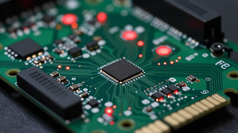
The Thermal Bottleneck of FR-4 in Automotive Electronics
FR-4, a composite material consisting of woven fiberglass cloth impregnated with epoxy resin, has served as the industry workhorse for decades due to its cost-effectiveness and mechanical versatility. However, as engine control units (ECUs) become smaller and more computationally intensive, the thermal conductivity of standard FR-4—typically ranging from 0.25 to 0.35 W/mK—is becoming a primary failure point. In high-power engine applications, the inability to efficiently transfer heat away from power electronics results in localized hot spots, premature dielectric breakdown, and significant reliability risks.
Material Limitations Under Thermal Stress
| Parameter | FR-4 Performance | Impact on ECUs |
|---|---|---|
| Thermal Conductivity | 0.25-0.35 W/mK | Poor heat dissipation requires bulky cooling solutions. |
| Glass Transition (Tg) | 130°C - 180°C | Material softens near engine operating limits. |
| CTE Mismatch | High (14-17 ppm/°C) | Increased solder joint fatigue under cycling. |
- Why does the Glass Transition Temperature (Tg) of FR-4 matter?
As FR-4 approaches its Tg, the resin matrix changes from a rigid state to a rubbery state, which leads to a rapid increase in the Coefficient of Thermal Expansion (CTE), often resulting in barrel cracking and via degradation. - How does high-power density impact FR-4 longevity?
Increased power density translates into higher thermal energy density. Because FR-4 is inherently a thermal insulator, it acts as a heat trap, accelerating the aging process of the epoxy and causing the insulation resistance to drop over time.
Understanding Ceramic PCB Substrates: Alumina and Aluminum Nitride
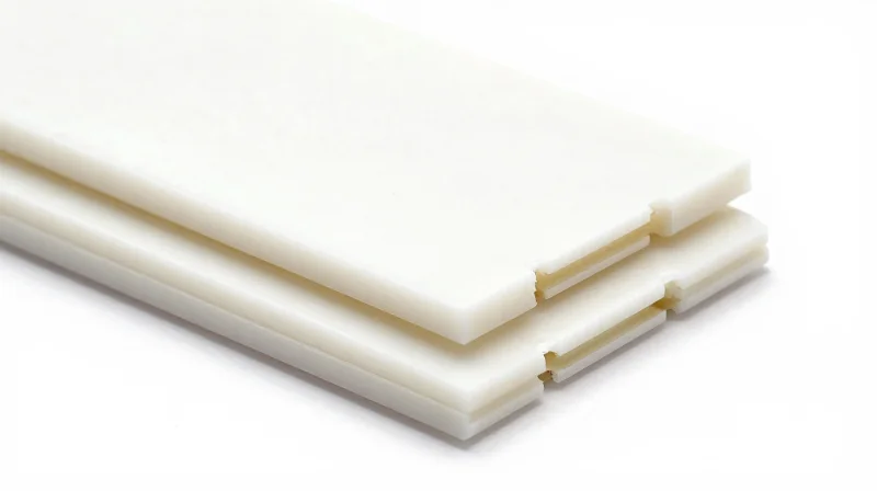
The Superior Thermal Profile of Ceramic Substrates
As Engine Control Units (ECUs) become more densely integrated, heat management has shifted from a secondary consideration to a primary engineering constraint. Unlike organic FR-4 laminates, which rely on additive thermal vias, ceramic substrates like Alumina (Al2O3) and Aluminum Nitride (AlN) offer intrinsic thermal conductivity, effectively acting as heat spreaders rather than thermal insulators.
Alumina (Al2O3): The Reliable Standard
Alumina is widely utilized in automotive power electronics due to its cost-to-performance ratio and excellent mechanical strength. It provides a thermal conductivity of approximately 20–30 W/mK—nearly ten times that of traditional FR-4—and offers high electrical resistivity, making it ideal for robust, long-term deployments in harsh engine bay environments.
Aluminum Nitride (AlN): The High-Power Specialist
Aluminum Nitride represents the vanguard of thermal management, boasting thermal conductivity reaching 170–230 W/mK. This material is essential for next-generation, high-speed switching ECUs where heat density exceeds the dissipation capacity of standard alumina. While more costly, its ability to match the Coefficient of Thermal Expansion (CTE) of silicon chips significantly enhances solder joint reliability under extreme thermal cycling.
| Material Property | FR-4 | Alumina (Al2O3) | Aluminum Nitride (AlN) |
|---|---|---|---|
| Thermal Conductivity (W/mK) | 0.2 - 0.5 | 20 - 30 | 170 - 230 |
| CTE (ppm/°C) | 14 - 17 | 6.5 - 7.5 | 4.5 - 5.0 |
| Max Operating Temp | 130°C | >1000°C | >1000°C |
Technical FAQs on Ceramic Substrates
- Why is CTE matching important for ECUs?
Engine components experience massive temperature swings. If the board material expands at a different rate than the silicon power die, the resulting mechanical stress leads to solder fatigue and connection failure. - Is Ceramic PCB manufacturing compatible with traditional SMT lines?
Yes, ceramic PCBs are generally compatible with standard Surface Mount Technology (SMT) processes, though they require specific considerations for laser dicing and metal paste printing rather than traditional chemical etching.
Thermal Management and Conductivity in Modern ECUs
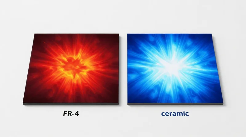
Thermal Conductivity and Heat Density Management
Modern engine control units face significant heat density challenges as electronic components shrink and power requirements intensify. While FR-4 relies on bulk material mass and secondary cooling paths, ceramic substrates like Aluminum Nitride (AlN) provide intrinsic thermal management, acting as both a dielectric layer and a heat spreader.
| Material Property | FR-4 Laminate | Alumina (Al2O3) | Aluminum Nitride (AlN) |
|---|---|---|---|
| Thermal Conductivity (W/m·K) | 0.2 - 0.4 | 20 - 30 | 170 - 230 |
| Coefficient of Thermal Expansion (ppm/°C) | 14 - 17 | 6.5 - 7.5 | 4.5 - 5.0 |
| Operating Temperature Limit | 130°C | >800°C | >1000°C |
Ceramic substrates bridge the gap between high-power semiconductor output and environmental thermal constraints. By utilizing direct-bonded copper (DBC) or thick-film metalization, these boards eliminate the thermal resistance bottleneck typically associated with organic adhesives found in standard PCBs.
Key Considerations for Thermal Design
- How does substrate choice impact component lifespan?
Ceramics significantly lower junction temperatures for power MOSFETs and IGBTs, reducing thermal cycling stress and fatigue, which directly increases the mean time between failures. - Can ceramic PCBs eliminate external heat sinks?
In many compact ECU designs, the high thermal conductivity of ceramic allows for the PCB itself to serve as the primary thermal path to the chassis, potentially reducing or eliminating the need for bulky, additive heat sink components. - Why is the Coefficient of Thermal Expansion (CTE) vital?
Ceramic substrates possess a CTE that closely matches silicon dies, minimizing mechanical strain at the solder joint interface during rapid engine temperature fluctuations.
Mechanical Durability Under Harsh Automotive Conditions
Vibration Resistance and Mechanical Integrity
Engine-mounted Electronic Control Units (ECUs) are subjected to constant high-frequency vibration and severe mechanical shock. While FR-4 laminates possess a degree of flexibility that can absorb some shock, their susceptibility to delamination and trace fatigue over thousands of thermal cycles often leads to premature failure. In contrast, advanced ceramic substrates, such as Alumina (Al2O3) or Aluminum Nitride (AlN), offer exceptional rigidity and hardness. This structural integrity prevents the board-level flexing that frequently cracks solder joints and separates internal copper layers in organic substrates.
CTE Matching and Thermal Stability
The primary cause of mechanical failure in high-temperature automotive electronics is the mismatch in the Coefficient of Thermal Expansion (CTE). When an ECU experiences rapid temperature swings, differing expansion rates between the PCB material and the soldered components cause immense mechanical stress. Ceramics provide a significant advantage by exhibiting CTE values closely matched to silicon dies and metallic housings, drastically reducing the shear stress on solder interconnects compared to the high CTE characteristic of epoxy-based FR-4.
| Parameter | FR-4 Laminate | Ceramic Substrate |
|---|---|---|
| Young's Modulus | Low (Flexible) | High (Rigid) |
| CTE Compatibility | Poor (High Mismatch) | Excellent (Low Mismatch) |
| Vibration Resilience | Susceptible to Flexing | High Mechanical Stability |
| Solder Joint Longevity | Limited by Fatigue | High Endurance |
Frequently Asked Questions
- Why is board rigidity critical for engine-mounted ECUs?
Engine environments generate high-frequency micro-vibrations. Excessive board flexing leads to solder joint cracking and catastrophic electrical failure; ceramic boards minimize this deflection. - Does the rigidity of ceramic make it prone to shattering?
While brittle compared to fiberglass, modern ceramic substrates are processed to handle the specific operational loads of automotive modules. When correctly supported in a housing, their structural stability far outweighs the fragility concerns of thin, unsupported laminates. - How does CTE matching extend the life of an ECU?
Matching the CTE reduces the mechanical tension at the interface of the chip, solder, and PCB during the rapid heating and cooling cycles of an engine, preventing fatigue-induced fractures.
High-Frequency Performance and Signal Integrity

The Challenge of High-Frequency Signal Integrity
As Engine Control Units (ECUs) shift toward autonomous drive integration and high-speed sensor arrays, the dielectric properties of the PCB substrate become a bottleneck. FR-4, while cost-effective, exhibits significant dielectric constant (Dk) and dissipation factor (Df) instability at high temperatures and high frequencies, leading to signal attenuation and timing jitter. Ceramic substrates, characterized by a lower and more stable dielectric loss, preserve signal wave integrity, which is critical for 77GHz radar and LiDAR components.
| Parameter | FR-4 (Standard) | Advanced Ceramic (AlN/Al2O3) |
|---|---|---|
| Dielectric Constant (Dk) | 4.2 - 4.8 (High variance) | 6.5 - 9.5 (Tight tolerance) |
| Dissipation Factor (Df) | 0.015 - 0.025 | 0.0005 - 0.002 |
| High-Frequency Stability | Poor due to moisture absorption | Excellent (Hygroscopic immunity) |
Dielectric Consistency in Thermal Extremes
In the proximity of engine combustion chambers, ECUs undergo rapid thermal cycling. Standard epoxy-glass laminates suffer from 'Dk drift,' where the dielectric constant shifts as the board temperature fluctuates. This instability alters the impedance of high-speed transmission lines, resulting in signal reflections and data errors. Ceramics exhibit near-zero Dk temperature coefficients, ensuring that impedance-controlled routing remains stable regardless of the engine's operational state.
Frequently Asked Questions
- Why does moisture absorption impact FR-4 signal integrity?
FR-4 is hygroscopic, meaning it absorbs ambient moisture. As the engine cycles between cold starts and high-heat operation, moisture levels inside the laminate change, causing the Dk to shift unpredictably. - Does ceramic substrate reduce electromagnetic interference (EMI)?
Yes, the superior dielectric consistency and potential for integrated thin-film shielding in ceramic packages reduce parasitic coupling, leading to lower radiated emissions compared to standard FR-4 multi-layer boards. - Are there specific frequency limits for these substrates?
While FR-4 degrades rapidly above 1-2 GHz, ceramic substrates are capable of maintaining performance well into the millimeter-wave (mmWave) spectrum, making them essential for 5G-connected vehicle telemetry.
Economic and Manufacturing Considerations
Cost-to-Performance Ratio Analysis
Transitioning from FR-4 to ceramic substrates involves a shift from commodity pricing models to high-value, performance-driven procurement strategies. While FR-4 remains the industry standard for cost-sensitive, low-thermal-stress applications, its failure rates in high-heat engine environments often necessitate expensive cooling add-ons or frequent unit replacements. Ceramic substrates, specifically Aluminum Nitride (AlN) and Alumina (Al2O3), require higher upfront capital expenditure but offer superior total cost of ownership (TCO) by eliminating the need for external heat sinks and improving overall product reliability.
| Metric | FR-4 Laminate | Ceramic Substrate |
|---|---|---|
| Material Cost | Low | High |
| Processing Complexity | Low (Standard) | High (Specialized) |
| Thermal Management Cost | Expensive (Active cooling required) | Low (Passive/Integrated) |
| Reliability in High Heat | Moderate | Excellent |
Manufacturing and Scalability Considerations
Mass-producing ceramic-based ECUs introduces significant shifts in assembly line requirements compared to traditional FR-4 lines. Manufacturers must account for the brittle nature of ceramic materials and the specific bonding techniques required for high-power semiconductor attachment, such as silver sintering or eutectic soldering, which are not standard in FR-4 manufacturing. However, the integration of advanced materials allows for smaller PCB footprints, enabling a reduction in housing material volume—a critical cost-saving factor for high-volume OEMs.
- Why do ceramic substrates require different manufacturing equipment?
Ceramic boards have higher thermal mass and different surface properties, necessitating specialized screen printing for thick-film deposition and unique reflow profiles compared to the industry-standard FR-4 pick-and-place lines. - How does PCB material choice impact long-term warranty costs?
Ceramics exhibit lower Coefficient of Thermal Expansion (CTE) mismatch, significantly reducing solder joint fatigue. This leads to fewer field failures in engine-mounted electronics, directly lowering warranty reserve fund requirements for automotive OEMs. - Is widespread adoption of ceramic PCBs realistic for mid-range vehicles?
Currently, ceramic substrates are economically viable primarily for high-performance or mission-critical ECUs where reliability offsets material costs; as ceramic manufacturing scales and material costs decrease, deeper market penetration is anticipated.
Future-Proofing Automotive Electronic Architectures

Architectural Evolution: Scaling for Electrification
As automotive electronic architectures transition from distributed ECUs to domain-based and zonal control architectures, the power density requirements placed on PCB substrates have surged. Traditional FR-4, while cost-effective for legacy comfort electronics, fails to provide the necessary thermal dissipation for high-power switching modules in electric powertrains. Integrating ceramic substrates allows for tighter component density and superior heat spreading, which are essential for maintaining system reliability over an increased vehicle lifespan.
Comparative Performance Metrics for Next-Generation Platforms
| Feature | FR-4 Substrate | Ceramic (AlN/Al2O3) Substrate |
|---|---|---|
| Thermal Conductivity | Low (0.25 W/mK) | High (20-200+ W/mK) |
| CTE Mismatch Potential | High | Low (Near-silicon match) |
| High-Frequency Signal Loss | Moderate/High | Negligible |
| System Longevity | Limited in high heat | Excellent in harsh environments |
Addressing Future Compute Requirements
Autonomous driving compute platforms demand stable, low-latency signal paths across high-temperature ranges. Ceramic substrates, particularly LTCC (Low-Temperature Co-fired Ceramic), offer exceptional dielectric stability that does not degrade under the constant thermal cycling of a modern vehicle. This stability is crucial for maintaining the precise timing and signal integrity required by advanced ADAS sensors, effectively future-proofing the board-level hardware against the obsolescence of current signal-sensitive materials.
Frequently Asked Questions
- Can ceramic PCBs coexist with FR-4 in the same ECU housing?
Yes, through modular design techniques like hybrid board construction or separate thermal zones, engineers can utilize ceramic inserts for power-intensive components while maintaining FR-4 for standard logic circuits. - How does ceramic substrate adoption impact total system cost?
While unit costs are higher, the reduction in cooling hardware, improved reliability, and longer lifecycle longevity often result in a lower total cost of ownership over the vehicle's operational life. - Is the transition to ceramic substrates mandatory for all new designs?
It is not mandatory for all modules, but it is becoming a critical requirement for power electronics, gate drivers, and high-speed sensing modules where thermal management is the primary bottleneck.
The transition from FR-4 to advanced ceramic substrates is no longer a luxury, but a necessity for surviving the extreme environments of modern high-performance engines. By embracing these materials, engineers can ensure lower failure rates and higher signal fidelity. Contact our engineering team today to discuss your next-generation hardware design and how we can help you integrate high-temperature PCB technology.
