
In the modern automotive landscape, the Tire Pressure Monitoring System (TPMS) has evolved from a convenience feature into a critical safety component. As vehicles endure extreme vibration, rapid temperature fluctuations, and moisture exposure, the reliability of the underlying PCB is non-negotiable. Designing for these harsh conditions requires a deep understanding of material science and electronic packaging. This guide provides engineers with the foundational knowledge to select materials that ensure long-term operation under the hood.
The Anatomy of a Harsh Automotive Environment
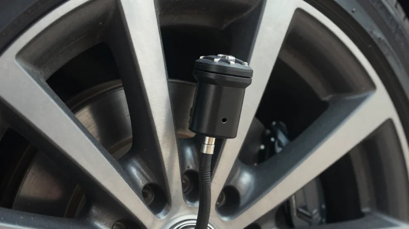
The automotive environment, particularly at the wheel end, subjects Tire Pressure Monitoring System (TPMS) electronics to continuous, extreme stress. Unlike under-hood or cabin electronics, TPMS sensors are mounted directly to the valve stem or the inner tire liner, exposing them to a unique combination of high-frequency road vibrations, centrifugal forces, and rapid thermal swings.
Primary Environmental Stressors
- Centrifugal Force
As wheels rotate at high speeds, TPMS sensors experience significant G-forces that can exceed 2,000G, risking structural integrity of solder joints and component mounting. - Thermal Cycling
Sensors endure temperatures ranging from -40°C during winter starts to over 125°C under sustained highway braking, causing differential thermal expansion in the PCB substrate. - Mechanical Vibration
Constant exposure to road debris and surface irregularities creates broadband random vibrations that induce fatigue in interconnections and copper traces. - Chemical Ingress
TPMS units must resist degradation from road salt, moisture, brake dust, and tire sealants that can compromise conformal coatings and dielectric strength.
Comparative Impact Analysis
| Stress Factor | Primary PCB Failure Mode | Design Mitigation |
|---|---|---|
| High G-Force | Solder joint fracture | Underfill encapsulation |
| Thermal Shock | Delamination/Cracking | High Tg PCB materials |
| Random Vibration | Via fatigue | Reinforced plating/staggered vias |
Material Selection for Harsh Environments
Selecting the correct laminate is critical. Standard FR-4 substrates often fail under sustained automotive conditions due to insufficient Glass Transition Temperature (Tg) and Coefficient of Thermal Expansion (CTE) mismatch. High-performance TPMS PCBs typically utilize high-Tg laminates, often reinforced with ceramic fillers to improve dimensional stability, ensuring that the copper traces remain intact despite the constant mechanical and thermal fluctuations intrinsic to tire rotation.
Substrate Selection: Beyond Standard FR-4
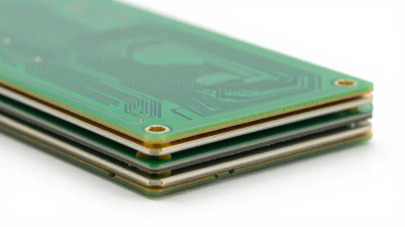
The Limitations of Standard FR-4 in TPMS Applications
Standard FR-4 laminates often prove inadequate for the demanding environment of Tire Pressure Monitoring Systems (TPMS). The primary failure modes involve excessive Coefficient of Thermal Expansion (CTE) and low glass transition temperatures (Tg), which lead to barrel cracking in plated through-holes (PTH) during the rapid temperature swings characteristic of road surface exposure. Automotive engineering standards necessitate materials that maintain mechanical integrity and dielectric stability well beyond the standard 130-140°C Tg of conventional epoxy resins.
Comparative Analysis of Advanced Substrate Materials
| Material Type | Tg (°C) | CTE (ppm/°C) | Primary Application |
|---|---|---|---|
| Standard FR-4 | 130-140 | 15-18 | Consumer electronics |
| High-Tg Epoxy | 170-180 | 12-14 | Engine-adjacent sensors |
| Ceramic-Filled Laminate | >200 | 8-10 | TPMS and high-reliability modules |
Selecting High-Performance Laminates: Engineering FAQ
- Why is CTE control vital for TPMS sensors?
CTE mismatch between the copper circuitry and the dielectric substrate causes mechanical strain. Controlling this factor prevents delamination and trace fractures caused by recurring thermal expansion cycles in wheel assemblies. - What advantages do ceramic-filled laminates offer?
Ceramic fillers reduce the effective CTE of the board while enhancing thermal conductivity. This helps dissipate heat from active components more efficiently than organic resin systems. - When should an engineer specify high-Tg over ceramic-filled?
High-Tg materials are preferred for cost-sensitive TPMS designs where temperature extremes are moderate, whereas ceramic-filled laminates are non-negotiable for harsh, high-vibration applications requiring superior dimensional stability.
Decoding Copper Weight Requirements
Determining Copper Weight for High-Reliability TPMS
In TPMS sensor design, copper weight selection is not merely about trace resistance; it is about establishing a robust thermal bridge. Given the small form factor of these sensors and the high ambient temperatures of wheel wells, engineers must carefully calibrate copper thickness to prevent localized heating while maintaining the mechanical precision required for high-frequency RF signaling. Utilizing heavier copper, such as 2 oz (70µm) or higher, is often necessary for power distribution rails to minimize voltage drop, whereas thinner copper, typically 0.5 oz (17µm) to 1 oz (35µm), is preferred for tight-pitch RF circuitry to maintain impedance control and etching accuracy.
Comparative Analysis: Impact of Copper Weight on Performance
| Copper Weight | Primary Application | Thermal Benefit | Etching Precision |
|---|---|---|---|
| 0.5 oz (17µm) | RF signal paths | Low (High thermal resistance) | Excellent (High density) |
| 1.0 oz (35µm) | Standard logic | Moderate | Good |
| 2.0 oz (70µm) | Power rails/Ground | High (Excellent dissipation) | Limited |
Essential Considerations for Automotive Copper Design
- How does copper weight influence thermal cycling resilience?
Heavier copper weights have a higher coefficient of thermal expansion, which can induce stress on plated through-holes (PTH) during rapid temperature cycling; therefore, it is vital to match copper weights with appropriate high-Tg substrates. - What is the tradeoff between current load and signal integrity?
While increased copper cross-sections reduce I2R losses and heat, they increase the parasitic capacitance of traces, which can degrade the high-speed signaling required for effective TPMS communication. - Why is etching factor critical for TPMS RF traces?
As copper thickness increases, the chemical etching process creates wider traces and larger trapezoidal cross-sections, which can deviate from calculated 50-ohm impedance requirements, causing signal reflections.
Ensuring Signal Integrity for Wireless Telemetry

For TPMS sensors, signal integrity is the difference between a reliable alert and a critical system failure. At the standard ISM bands of 315MHz and 433MHz, PCB layout must prioritize minimal insertion loss and robust shielding against the electrically noisy automotive chassis environment.
Designing for RF Impedance Consistency
To prevent signal reflection and maximize power transfer from the radio IC to the antenna, strict 50-ohm impedance matching is mandatory. This requires tight control over trace width, dielectric height, and the dielectric constant (Dk) of the chosen substrate material. Even minor variations in manufacturing tolerances can shift the resonant frequency, causing massive performance degradation in the compact TPMS module.
| Design Factor | Impact on Signal Integrity | Recommended Strategy |
|---|---|---|
| Trace Geometry | Impedance mismatch | Controlled impedance routing |
| Ground Planes | Return path discontinuity | Solid ground plane under RF traces |
| Via Placement | Inductive parasitic effects | Stitching vias near RF transitions |
Mitigating EMI and External Interference
TPMS modules are subjected to significant electromagnetic interference (EMI) from the vehicle's ignition system, electric motors, and infotainment electronics. Implementing a multi-layer stack-up with a dedicated internal ground reference layer is essential to confine return currents and minimize the loop area of high-frequency traces.
- Trace Isolation
Keep high-speed digital signals physically separated from RF signal paths to prevent crosstalk and noise injection. - Antenna Tuning
Ensure clear copper-keepout zones around the antenna area to maintain efficiency and prevent detuning caused by surrounding chassis materials. - Filtering
Incorporate low-pass or band-pass filters near the RF front-end to attenuate harmonic emissions and adhere to automotive EMC regulations.
Frequently Asked Questions on RF Integrity
- Why is FR-4 often avoided for RF sections in TPMS?
Standard FR-4 exhibits high loss tangent (Df) and inconsistent dielectric constant at high frequencies, which leads to significant signal attenuation at 433MHz. - How does moisture affect signal integrity?
Automotive sensors face humidity and icing; high-quality, low-moisture-absorption laminates prevent impedance shifts that would occur if the substrate absorbed environmental moisture.
Thermal Management Strategies

Mitigating Localized Hotspots
In high-density Tire Pressure Monitoring System (TPMS) modules, the proximity of RF transceivers and microcontrollers often leads to thermal concentration. To prevent device degradation, designers must move beyond passive cooling by utilizing thermal vias and strategic copper geometry to create low-resistance paths for heat transfer toward the outer housing or heat-spreading layers.
Thermal Vias and Copper Pours
Thermal vias act as vertical conduits that bridge the inner layers to ground planes, essentially transforming the entire PCB stack into a heat spreader. When coupled with heavy copper pours—typically 2oz or higher—this strategy ensures that localized heat from high-current switching components is effectively dissipated across a broader surface area.
| Technique | Primary Function | Implementation Tip |
|---|---|---|
| Thermal Vias | Vertical heat conduction | Use a tight grid pattern under high-heat IC pads. |
| Copper Pours | Lateral thermal distribution | Maintain clear ground return paths to avoid EMI. |
| Solder Mask Opening | Enhanced emissivity | Expose copper at heat-sink contact points. |
Frequently Asked Questions
- How many thermal vias are necessary under a TPMS MCU?
While there is no single number, a pitch of 0.5mm to 0.8mm for thermal vias is recommended; the goal is to maximize the copper fill percentage directly beneath the component package. - Does copper thickness negatively impact signal integrity?
Increased copper weight can affect impedance control due to side-etching during fabrication, so always re-calculate trace widths to ensure signal integrity remains within target tolerances. - Is it better to use solder-filled or plugged vias?
For thermal efficiency, copper-filled or solder-filled vias are superior as they increase the cross-sectional area for heat transfer, whereas hollow vias rely on air gaps which are poor thermal conductors.
Compliance with Automotive Reliability Standards
Core Automotive Reliability Frameworks
To achieve automotive-grade reliability, designers must prioritize adherence to global standards that govern stress testing, failure mode analysis, and systematic safety management. Failure to comply with these standards often results in premature sensor failure, critical in safety-sensitive applications like Tire Pressure Monitoring Systems (TPMS).
| Standard | Primary Focus | Application in TPMS |
|---|---|---|
| AEC-Q100 | IC Stress Testing | Validates the robustness of integrated circuits against environmental and electrical stress. |
| ISO 26262 | Functional Safety | Ensures the system can detect and respond to internal faults, achieving ASIL compliance. |
| IPC-6012 | Rigid PCB Qualification | Defines performance specifications for fabrication and structural integrity of the base PCB. |
Engineering for Functional Safety (ISO 26262)
ISO 26262 dictates that the PCB must be designed with fault-tolerance in mind. For TPMS, this involves implementing redundant signal paths and rigorous diagnostic coverage. Engineers must perform Failure Mode and Effects Analysis (FMEA) to identify how potential substrate delamination or solder joint fatigue could manifest as system-level safety violations.
Common Compliance Queries
- Why is AEC-Q100 verification critical for TPMS sensors?
TPMS sensors operate in extreme wheel-well conditions, including intense vibration and wide temperature swings; AEC-Q100 ensures components survive these cycles without catastrophic degradation. - Does ISO 26262 apply strictly to software?
No, ISO 26262 covers the entire hardware-software integration, meaning PCB trace routing, component selection, and thermal management strategies must be documented as part of the safety case. - How does PCB selection influence ASIL ratings?
The choice of high-Tg (glass transition temperature) laminates and specialized surface finishes directly affects the reliability level, which is a foundational requirement for achieving higher ASIL classifications.
Surface Finish and Protective Coatings
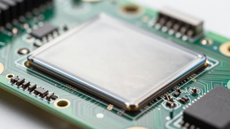
Surface Finish Selection for Automotive Durability
The choice of surface finish determines the solderability, wire bondability, and long-term corrosion resistance of the TPMS module. For automotive applications, the finish must withstand extreme thermal cycling and potential exposure to chemical contaminants.
| Finish | Pros | Cons | Automotive Suitability |
|---|---|---|---|
| ENIG | Excellent planarity, good oxidation resistance | Risk of black pad, higher cost | High; ideal for fine-pitch BGA components |
| OSP | Cost-effective, flat surface | Limited shelf life, sensitive to handling | Low to Medium; requires careful processing |
| ENEPIG | Broad solder/wire bond compatibility | Complex, expensive process | Very High; superior for critical sensor nodes |
Protective Coatings and Moisture Mitigation
Conformal coatings serve as the final barrier against environmental stressors including humidity, salt spray, and automotive fluids. Because TPMS sensors are often located inside the wheel well or tire assembly, they require specialized protective materials to prevent electrochemical migration and leakage currents.
- Why is conformal coating necessary for TPMS?
Automotive environments expose electronics to rapid temperature swings and high humidity. Coatings prevent condensation-induced shorts and protect against road salt corrosion. - Which materials offer the best protection?
Silicone and Parylene coatings are generally preferred due to their superior thermal stability and moisture barrier properties compared to standard acrylics. - Does coating affect RF performance?
Yes, the dielectric constant of the coating can shift the resonant frequency of internal antennas. Engineering teams must compensate for this shift during the RF tuning phase.
When finalizing the manufacturing specification, ensure that the coating process is compatible with the selected surface finish to prevent delamination. Compliance with IPC-CC-830 standards remains the industry benchmark for verifying coating performance in safety-critical automotive electronics.
Design for Manufacturing (DFM) Optimization
Streamlining Manufacturing for High-Volume TPMS
Design for Manufacturing (DFM) in the context of automotive TPMS requires a synergistic approach between electrical performance and mechanical fabricatability. By standardizing board stack-ups and panelization strategies early in the design phase, engineers can significantly reduce per-unit costs and mitigate assembly risks inherent in compact sensor modules.
Core DFM Strategies for Automotive PCBs
- Panelization Efficiency
Utilize optimal board nesting to maximize panel utilization, targeting at least 85% area usage. Incorporate break-away tabs or v-scoring appropriately for automated singulation. - Aspect Ratio Management
Keep via aspect ratios within the 6:1 to 8:1 range for standard drilling processes to ensure consistent plating reliability throughout the barrel, critical for TPMS safety. - Component Clearance and Fiducials
Maintain a minimum of 0.5mm clearance from board edges and utilize global/local fiducials to enable high-precision automated optical inspection (AOI) and placement.
DFM Feature Comparison Table
| Parameter | Recommended Standard | Impact on Production |
|---|---|---|
| Min Trace/Space | 0.1mm / 0.1mm | Increases yield/reduces etch errors |
| Via Diameter | ≥ 0.25mm | Avoids laser drill necessity |
| Copper Weight | 0.5 oz to 1 oz | Balances thermal/manufacturing ease |
Minimizing Post-Assembly Failure
To achieve automotive-grade reliability, avoid 'Design for Complexity' traps. Standardizing finish types like Electroless Nickel Immersion Gold (ENIG) or Immersion Tin across the production run ensures consistent solder joint formation. Furthermore, ensuring that all silkscreen and solder mask registration tolerances are accounted for at 0.05mm prevents misaligned components during high-speed pick-and-place, ultimately driving down scrap rates in mass production environments.
Selecting the right PCB material stack-up is the cornerstone of TPMS reliability, transforming an automotive sensor from a simple circuit into a mission-critical component. By focusing on thermal endurance and signal integrity, engineers can design for the long-term safety mandates of the modern automotive industry. Contact our engineering team today to review your material stack-up or to request a technical consultation for your next automotive project.
