Checking a Capacitor: A Comprehensive Guide with Multimeter
2025.01.25
Capacitors are fundamental components in countless electronic devices, playing a crucial role in energy storage and circuit stability. Just like a battery, they store electrical charge, and over time, they can degrade or fail. Checking a capacitor properly is crucial for maintaining electronic devices and diagnosing potential circuit problems. This article explores effective methods for checking a capacitor, focusing on multimeter techniques to identify issues and ensure circuit safety and performance.
Understanding Capacitors and Their Role
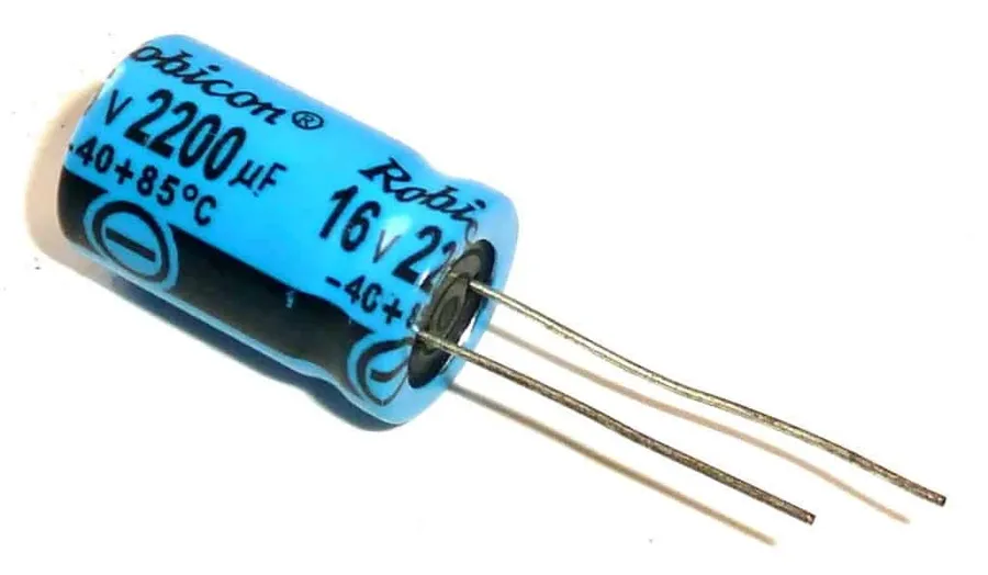
Various Capacitors
Capacitors are fundamental electronic components designed to store electrical energy in an electric field. They are ubiquitous in circuits, acting as temporary energy reservoirs, filters, and timing elements. Understanding their behavior is crucial for diagnosing circuit malfunctions, especially since capacitor failure is a frequent cause of electronic device issues.
Capacitors are primarily used for energy storage, smoothing voltage fluctuations, and filtering specific frequencies of electrical signals. Their function is similar to a small rechargeable battery, which will charge quickly and discharge when needed. For example, they are used to smooth out the rectified DC voltages in power supplies, in timing circuits, and to block DC current while allowing AC to pass.
Capacitor failures can stem from various factors, including aging, excessive voltage, high temperatures, or physical damage. Common failure modes include short circuits, open circuits, or degradation of capacitance value. In many situations, when a circuit exhibits erratic or unexpected behavior, a failing capacitor can often be identified as the culprit.
Safety First: Discharging a Capacitor Before Testing
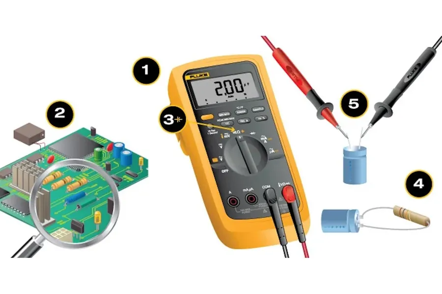
Discharging a Capacitor
Before testing any capacitor, it is paramount to discharge it completely. Capacitors store electrical energy, and failure to discharge them can lead to dangerous electrical shocks or damage your testing equipment, especially multimeters. This section outlines the importance of this step and provides safe methods for capacitor discharge.
The energy stored in a capacitor is determined by the equation E = 1/2 CV^2, where E is energy in Joules, C is capacitance in Farads, and V is the voltage across the capacitor. Even seemingly small capacitors can store a significant and dangerous amount of energy at high voltage.
Why Discharge Capacitors? A charged capacitor can deliver a significant electric shock, potentially causing injury or even death. Moreover, testing a charged capacitor with a multimeter may damage the instrument due to the sudden rush of current. The stored energy can also lead to inaccurate readings.
Safe Discharge Methods The safest method involves using a discharge resistor of appropriate size. This resistor allows the stored charge to bleed off in a controlled manner. Never use a direct short circuit (e.g., a wire) to discharge a capacitor, as this can cause a surge of current that damages the capacitor and presents a shock hazard. Additionally, ensure the resistor is rated to handle the capacitor’s voltage and energy capacity.
Discharge Procedure To safely discharge a capacitor, connect the resistor to the capacitor terminals using insulated test leads. The resistor value depends on the capacitor's voltage and capacitance but is generally in the range of 1k to 100k ohms with a power rating sufficient to handle the energy. Monitor the voltage across the capacitor with a multimeter set to DC voltage mode until it reaches zero volts or a negligible value. Allow time for the capacitor to fully discharge – don't be hasty. Double-check using your multimeter to ensure full discharge before proceeding with any other tests.
Checking a Capacitor with a Multimeter: Capacitance Mode
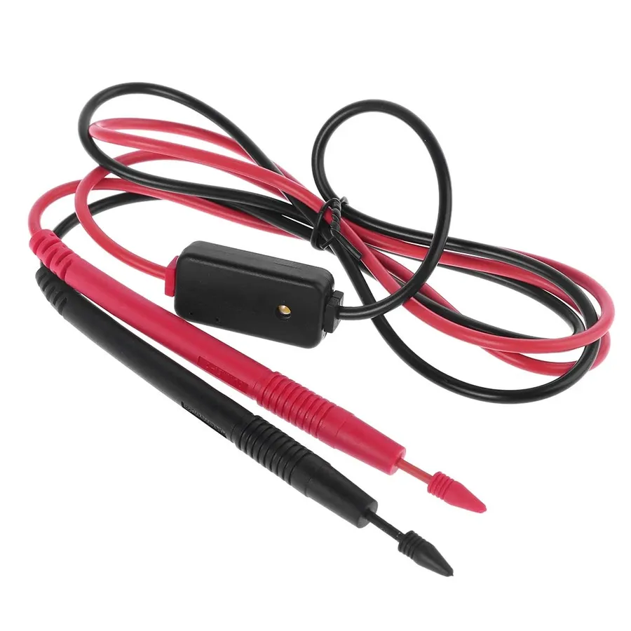
Measuring Capacitance
The capacitance mode on a digital multimeter is the most direct method for verifying a capacitor's ability to store charge, providing a quantitative measurement of its capacitance value in Farads (F). This mode is essential for assessing if a capacitor's performance aligns with its stated specifications.
The following steps detail the procedure for checking a capacitor using the capacitance mode of a multimeter:
Step 1: Select Capacitance Mode Turn on your digital multimeter and set it to the capacitance mode. This is usually indicated by a symbol that looks like a capacitor symbol (||) or by the label 'F' for Farads. Ensure you select the correct range for the capacitor being tested; start with the highest range if unsure and work downwards to get a precise reading.
Step 2: Prepare the Capacitor Before testing, ensure the capacitor is fully discharged. While the multimeter may attempt to discharge a small amount, it's paramount to manually discharge the capacitor for safety, as discussed in the previous section, using a resistor. Disconnect the capacitor from the circuit before proceeding.
Step 3: Connect the Multimeter Probes Carefully connect the multimeter probes to the capacitor terminals. Ensure that the connection is firm and making good electrical contact. The polarity of the probes does not matter for non-polarized capacitors (e.g., ceramic, film), but if testing polarized capacitors (e.g., electrolytic), connect the red probe to the positive terminal and the black probe to the negative terminal.
Step 4: Read the Capacitance Value Once connected, observe the multimeter's display. The reading shown is the capacitor's capacitance value, usually displayed in Farads (F), microfarads (µF), nanofarads (nF), or picofarads (pF), depending on the scale. Note this reading for analysis.
Step 5: Analyze the Results Compare the measured capacitance to the capacitor's specified value. Most capacitors have a tolerance, typically indicated on the capacitor itself (+/- 5%, +/- 10%, etc.) or in its datasheet. A healthy capacitor will usually show a value within this tolerance range. A significant deviation suggests that the capacitor may be failing or has failed entirely.
It is imperative to note that the multimeter is not capable of testing a capacitors true quality and will only be able to tell if a capacitor is completely dead. For true testing an equivalent series resistance (ESR) meter is required.
Checking a Capacitor with a Multimeter: Resistance Mode
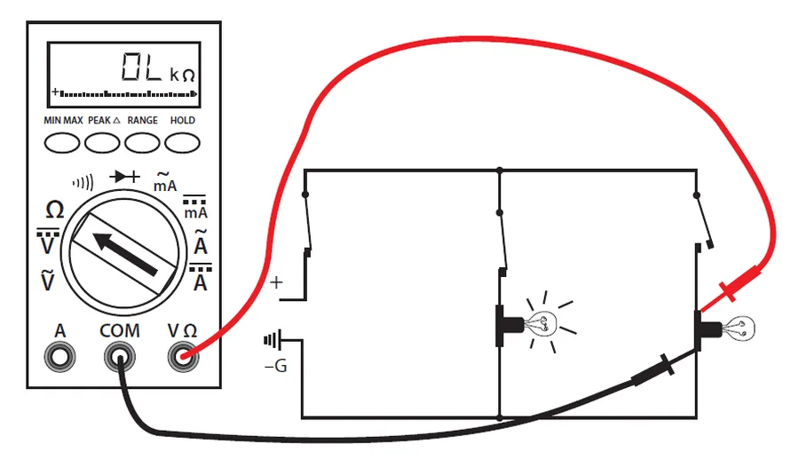
Measuring Resistance
While the capacitance mode is the primary method for assessing a capacitor's health, using a multimeter in resistance mode offers a valuable alternative, particularly for detecting shorts or opens, and is a good cross-reference to the capacitance measurement. This method relies on observing the charging behavior of the capacitor.
When using resistance mode, it's crucial to understand that a healthy capacitor will initially exhibit low resistance, which will then steadily increase as the capacitor charges. Conversely, a shorted capacitor will exhibit a continuously low resistance reading, while an open capacitor will show a very high or infinite resistance reading immediately. This behavior allows us to quickly identify gross faults.
Set the Multimeter to Resistance Mode Turn on your multimeter and select the resistance (Ω) mode. Start with the highest resistance range available, as this will help avoid damaging the multimeter if the capacitor is shorted. For most multimeters the selection will be on the rotary dial and can be designated with the omega (Ω) symbol.
Connect the Multimeter Probes Connect the multimeter probes to the capacitor terminals, observing polarity for polarized capacitors. If polarity is not observed, the capacitor will charge to the wrong polarity and may give an incorrect reading or damage to the capacitor. Typically, the red probe connects to the positive terminal of polarized capacitors, and black goes to the negative. For non-polarized capacitors, the connection can be done arbitrarily.
Observe the Resistance Reading A healthy capacitor should initially show a very low resistance, this is due to the initial charging current, then it will gradually climb towards infinity (open circuit) as the capacitor charges. The actual reading and speed will depend on the capacitor's value and the multimeter's internal circuitry. However, a noticeable and steady increase is indicative of proper function. If the resistance is low and stays low the capacitor is likely shorted, if the resistance is infinite and stays infinite the capacitor is likely open.
Interpret the Results A capacitor that charges is generally functioning correctly. A consistently very low reading indicates a short circuit, while an unchanging high or infinite reading suggests an open circuit, also consider if the initial reading is extremely low, it's also a sign of a high ESR capacitor. It is good practice to observe the readings and compare to other known-good capacitors in the same circuit or application. This will increase the likelihood of a correct diagnosis.
Analyzing Multimeter Readings for Capacitor Health
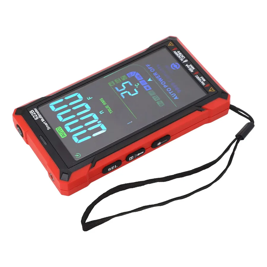
Multimeter Display
Interpreting multimeter readings is crucial for assessing capacitor health. These readings, whether capacitance or resistance measurements, provide insights into whether a capacitor is functioning correctly, has failed, or is degraded. Understanding the expected values and tolerances is essential for accurate diagnosis.
Reading Type
Normal Capacitor
Shorted Capacitor
Open Capacitor
Degraded Capacitor
Capacitance (C)
Reading close to the rated capacitance value within tolerance.
Reading close to zero. Capacitor is shorted.
Reading of zero or erratic. Indicates an open circuit.
Significantly lower reading than rated capacitance.
Resistance (Initial)
Initially low resistance, then rising to infinity
Near-zero resistance that stays very low.
Infinite resistance right away.
Lower initial resistance but may not climb to infinity
Resistance (Final)
Infinite resistance (or very high).
Low resistance.
Infinite resistance.
May not reach infinite or very high resistance.
Capacitor tolerances, typically expressed as a percentage of the rated capacitance, should be considered. For instance, a capacitor rated at 100µF with a ±20% tolerance may show a reading between 80µF and 120µF. Deviations outside this range suggest that the capacitor's health may be compromised. The readings depend on the condition of the capacitor as summarized in the table.
Checking a Capacitor In-Circuit vs. Out-of-Circuit
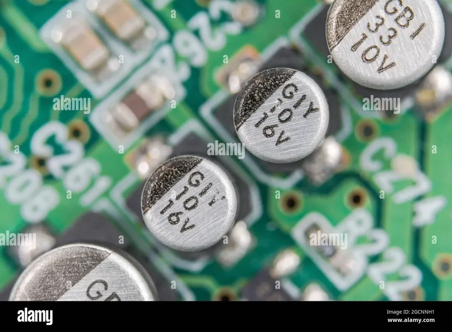
Capacitor on Circuit Board
Testing a capacitor's health can be approached in two primary ways: in-circuit and out-of-circuit. Each method presents unique advantages and disadvantages that must be considered to ensure accurate assessment and prevent potential misdiagnoses.
Aspect
In-Circuit Testing
Out-of-Circuit Testing
Measurement Accuracy
Lower accuracy due to parallel circuit components influencing readings.
Higher accuracy as the capacitor is isolated from other components.
Ease of Testing
More convenient as it eliminates the need for component removal.
Requires more time and effort to remove the component for testing.
Risk of Interference
Susceptible to interference from other components, leading to inaccurate results.
Minimal risk of interference, providing a more direct reading of the capacitor's characteristics.
Component Integrity
No risk of damaging the circuit or component during testing.
Risk of physical damage during removal and installation, if not done properly.
Detection of Leakage
More difficult to detect leakage if parallel components are present.
Easier to detect leakage and other defects such as physical damage.
Special Considerations
May require understanding of circuit topology to interpret readings. Requires the understanding of parallel and series circuits.
Measurements represent the capacitor directly, but the removed component should be tested quickly.
In-circuit testing is often faster and more convenient, but the presence of other components can affect measurements. For example, components connected in parallel with the capacitor can alter both capacitance and resistance readings. If in-circuit testing suggests a problem, the capacitor should be removed for out-of-circuit testing to confirm its condition.
Out-of-circuit testing, though requiring more effort, provides a much more accurate assessment of the capacitor's true condition. This method isolates the capacitor, eliminating the effects of other components. However, care must be taken when removing and reinstalling the capacitor to avoid damage. It is critical to ensure correct re-insertion into the circuit to prevent further complications. If the out-of-circuit test indicates capacitor failure, the capacitor must be replaced.
Frequently Asked Questions About Checking Capacitors
This section addresses common inquiries regarding capacitor testing, providing clear and concise answers to help users understand the nuances of capacitor health assessment.
How do you determine if a capacitor is bad? A capacitor is considered bad if it exhibits several key symptoms: abnormal capacitance readings (outside of the stated tolerance), very low resistance (indicating a short), very high resistance (indicating an open circuit), visual signs of damage (such as bulging or leaking), or failure to hold a charge. Multimeter tests using capacitance and resistance modes can help diagnose these issues.
How should I test a run capacitor using a multimeter? To test a run capacitor with a multimeter, set the multimeter to capacitance mode, select the appropriate range for the capacitor's stated capacitance, and then connect the multimeter probes to the capacitor terminals. Compare the measured value with the capacitor's rated capacitance; a significant deviation indicates a problem. Additionally, observe the resistance initially using the resistance mode; a healthy capacitor should show low resistance which increases over time until an open circuit is shown as the capacitor charges. A constant low or high resistance indicates an issue.
Can I test a capacitor without discharging it first? No, it is imperative to discharge a capacitor before testing it to avoid any electric shock hazard and damage to your measuring instrument. A charged capacitor can store a significant amount of energy which can potentially injure you and give inaccurate or damaging readings. Always use a proper discharging procedure before proceeding.
Should there be continuity through a capacitor during a resistance test? No, a capacitor should not show continuous continuity after a short period in a healthy circuit. When testing a discharged capacitor using the resistance mode, the resistance should initially appear very low as the multimeter attempts to charge the capacitor, then increase over time until the multimeter shows an open circuit or infinite resistance as the capacitor becomes charged, this behavior indicates the capacitor is charging. Continuous low resistance indicates a short circuit, continuous open resistance can indicate an open circuit.
What does a zero or near-zero capacitance reading on a multimeter indicate? A zero or near-zero capacitance reading usually indicates that the capacitor is either completely open or severely damaged. It cannot store charge and will not function properly in the circuit. Further testing using the resistance mode might be necessary to confirm the precise type of damage.
Can I test a capacitor in-circuit? While testing a capacitor in-circuit is possible with a multimeter, it's generally more accurate to remove the capacitor from the circuit for testing if possible. Other components in the circuit can influence the readings, which may lead to false positives. If in-circuit testing is performed, ensure power is removed from the circuit, and be aware that readings could be affected by surrounding components
How do I interpret capacitance value tolerances? Capacitors typically have tolerance ratings indicating how much the actual capacitance may deviate from its stated value, for example a 10% tolerance capacitor with a stated capacitance of 10 uF may have a capacitance measurement between 9 uF and 11 uF when measured with a multimeter. A measurement significantly outside of these parameters indicates a failed component.
Troubleshooting Common Capacitor Problems
Visual inspection of capacitors often reveals critical clues about their health, supplementing multimeter-based diagnostics. Physical deformities such as bulging or leaking are strong indicators of internal damage and imminent failure. These issues frequently correlate with abnormal multimeter readings, providing a holistic view of the capacitor's condition.
Bulging Capacitor A bulging capacitor, particularly at the top, often indicates excessive internal pressure due to the electrolyte breaking down from overheating or overvoltage. This internal damage leads to a loss of capacitance and increased equivalent series resistance (ESR). Multimeter readings may show decreased capacitance or elevated ESR values.
Leaking Electrolyte Visible electrolyte leakage suggests the capacitor’s internal seals have failed, typically from overheating or aging. Leaking electrolyte can corrode adjacent components and significantly impact circuit performance. Multimeter tests may reveal a short circuit or very low capacitance.
Physical Damage Cracks, fractures, or other physical damage to the capacitor's body indicate mechanical stress or mishandling. Such damage can lead to unpredictable electrical behavior. Multimeter readings can vary from a complete open circuit to a short circuit, depending on the extent of the damage. If the ceramic body of the capacitor is chipped or cracked the internal plates may short.
Corrosion on Terminals Corroded terminals indicate a breakdown of the capacitor's external protection, often due to moisture or environmental exposure. This can cause high resistance at the connection point. Testing may show very low or no capacitance as the connection to the internal structure may be compromised
When correlating visual inspection with multimeter readings, always prioritize safety. A visibly damaged capacitor might still retain a charge and should be discharged carefully before handling. Note that while visual cues are helpful, they don't replace quantitative electrical testing via multimeter; they serve as additional indicators to pinpoint the root cause of malfunction.
Practical Tips for Accurate Capacitor Testing
Ensuring accurate capacitor testing with a multimeter requires attention to detail and adherence to best practices. These tips address environmental factors, measurement techniques, and the proper use of your multimeter to obtain reliable results. By following these guidelines, you can minimize errors and improve the consistency of your measurements.
Environmental Conditions Temperature and humidity can affect capacitor readings. Ideally, perform tests under stable ambient conditions, away from extreme temperature fluctuations and high humidity, as these can alter the effective capacitance and introduce measurement errors.
Proper Lead Placement When connecting the multimeter leads to the capacitor, ensure that they make good contact with the capacitor terminals. Poor contact can result in inaccurate readings due to added resistance or unstable capacitance measurements. Use clean leads, and avoid touching the conductive parts during measurement.
Discharge Before Testing Always discharge the capacitor completely before any testing. A charged capacitor will provide inaccurate readings, and potentially damage the multimeter or pose a safety risk. Verify the discharge of the capacitor by observing no voltage reading with the multimeter.
Calibration of Multimeter Ensure your multimeter is correctly calibrated and in good working order. An improperly calibrated meter will produce incorrect readings. Verify calibration by testing known components, if necessary, or use a dedicated multimeter calibrator. Multimeters have inherent accuracy limits based on the measurement range, and measurement error should be considered when evaluating the capacitor's value.
Capacitor Handling Avoid touching the capacitor's leads or body while taking measurements. Direct contact can affect the readings, especially for sensitive measurements of low capacitance values. Use insulated test leads or clips for connection. Handle capacitors carefully, as physical damage can affect electrical performance and lead to inaccurate results. Be mindful of static discharge.
Understanding ESR Equivalent Series Resistance (ESR) can significantly affect capacitor performance, particularly in high frequency applications. While multimeters can provide an ESR reading, if available, remember that capacitance and ESR are both important in a comprehensive capacitor evaluation.
Use Appropriate Measuring Range Set the multimeter to an appropriate capacitance range. For example, if the capacitor is rated at 10uF, using a 200uF range will provide a more precise reading compared to a higher range like 2000uF, which sacrifices resolution. Always start with a range higher than you expect, then reduce to the lowest range possible for optimal accuracy.
Checking a capacitor correctly is a vital skill for any electronics enthusiast or professional. By understanding how to safely discharge a capacitor and using your multimeter correctly in both capacitance and resistance modes, you can effectively diagnose and address capacitor-related issues. This guide ensures you can maintain and troubleshoot circuits, thereby preventing failures and ensuring the longevity of your electronic devices. Remember, safety is paramount—always discharge capacitors before testing.