
In the fast-evolving landscape of automotive engineering, the Transmission Control Unit (TCU) serves as the brain of the vehicle's powertrain. As modern vehicles face increasingly severe thermal and mechanical stresses, selecting the right Printed Circuit Board (PCB) is no longer just a design choice—it is a mission-critical reliability requirement. This guide explores the engineering standards necessary to ensure your TCU components endure the rigors of the road.
Understanding the Harsh Automotive Environment
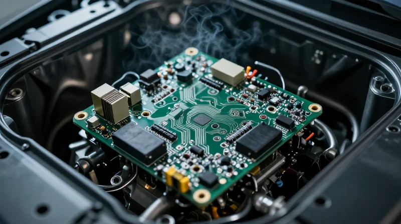
Transmission Control Units (TCUs) operate in some of the most unforgiving locations within a modern vehicle. Unlike standard consumer electronics, these printed circuit boards (PCBs) are situated in close proximity to the drivetrain, subjecting them to continuous stress cycles that can lead to catastrophic failure if the substrate, copper, and surface finishes are not specified correctly. Engineering for these environments requires a deep understanding of multi-modal stressors that act simultaneously on the hardware.
Environmental Stress Factors
| Environmental Factor | Primary Engineering Challenge | Failure Mechanism |
|---|---|---|
| Thermal Cycling | Coefficient of Thermal Expansion (CTE) mismatch | Via barrel cracking and solder joint fatigue |
| High-Frequency Vibration | Mechanical resonant frequencies | Interconnect fracture and solder joint micro-cracking |
| Fluid Contamination | Chemical degradation of dielectric | Conductive anodic filament (CAF) growth |
The Impact of Thermal and Mechanical Cycles
TCUs experience aggressive 'cold-start to operating-temp' cycles, often ranging from -40°C to +150°C. This oscillation causes repetitive expansion and contraction of board materials. If the CTE of the dielectric material is not closely matched to the copper circuitry, the internal vias—the tiny tunnels linking layers—become subject to immense tensile stress, eventually leading to barrel fractures. Simultaneously, the engine's mechanical vibration introduces cyclic fatigue, which accelerates the degradation of solder joints that have already been weakened by thermal stress.
Chemical Exposure and Reliability
Beyond physical stress, TCUs are frequently exposed to automotive fluids including transmission oil, synthetic lubricants, and de-icing road salts. These chemicals are highly aggressive and can penetrate low-quality conformal coatings or substrate voids, facilitating Conductive Anodic Filament (CAF) growth. CAF is a dendritic growth that forms between conductors, creating short circuits that can lead to intermittent signal errors or total TCU failure.
Frequently Asked Questions
- Why is CTE matching crucial for high-performance TCUs?
Matching the Coefficient of Thermal Expansion ensures that the board materials expand at the same rate as the copper, preventing mechanical strain on vias and avoiding micro-cracks during extreme thermal swings. - How do engineers mitigate the risk of fluid ingress?
Engineers mitigate fluid risks by specifying high-Tg (glass transition temperature) laminates with low moisture absorption rates and applying automotive-grade conformal coatings that resist chemical degradation.
Core Material Selection: Beyond Standard FR-4
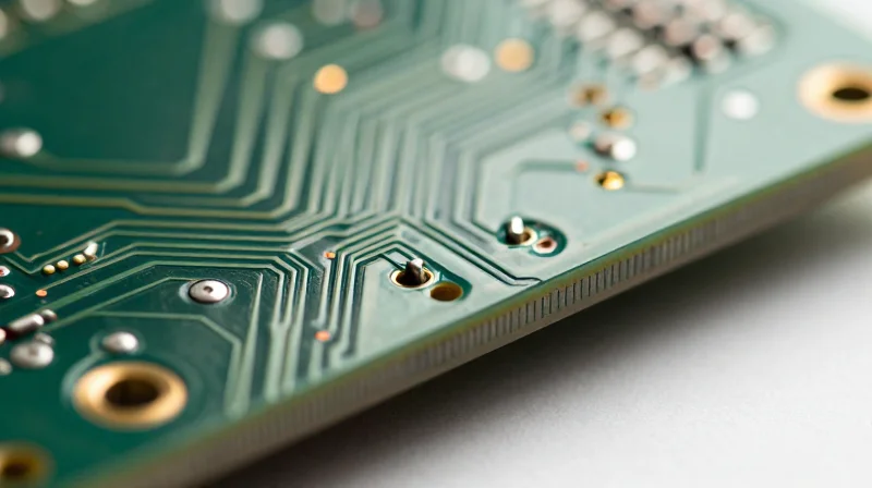
Standard FR-4 laminates frequently fail in TCU applications due to their inability to withstand rapid, extreme thermal cycling. High-performance TCU engineering requires moving toward advanced materials that offer superior Glass Transition Temperature (Tg) thresholds and Coefficient of Thermal Expansion (CTE) matching to prevent delamination and solder joint failure under mechanical stress.
High-Tg Laminates vs. Ceramic-Filled Materials
| Material Type | Key Advantage | Primary Application |
|---|---|---|
| High-Tg FR-4 | Improved thermal stability | General automotive modules |
| Ceramic-Filled | Superior CTE control | Direct-mount engine sensors |
| PTFE-based | Low signal loss | High-frequency radar/V2X |
Key Material Selection Criteria
- Why is Tg critical for TCUs?
The Glass Transition Temperature (Tg) marks the point where a polymer transitions from a rigid, glassy state to a rubbery state; a higher Tg ensures the material maintains structural integrity when exposed to the high under-hood temperatures of active driving cycles. - How does ceramic filling assist in harsh environments?
Ceramic fillers reduce the Coefficient of Thermal Expansion (CTE) of the substrate, effectively matching it closer to copper traces and silicon dies, which minimizes mechanical stress on through-hole vias during prolonged thermal expansion. - What role does moisture absorption play?
High-performance materials like polyimides or advanced epoxies exhibit lower moisture absorption rates, which is vital for preventing popcorn effects and interlayer corrosion in humid or chemically aggressive automotive atmospheres.
Strategic Material Implementation
Selecting the right material requires balancing cost with thermal resilience. For most TCUs, a hybrid stack-up is recommended, utilizing ceramic-filled high-frequency laminates for signal layers and high-Tg core materials for the inner structure. This dual approach provides the required dimensional stability without incurring the excessive cost of pure ceramic circuit boards.
Advanced Thermal Management Strategies
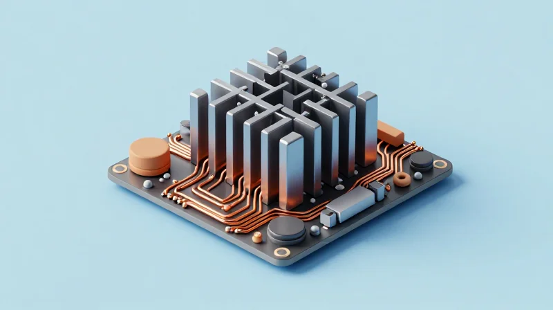
Advanced Thermal Management Strategies
As Transmission Control Units (TCUs) shrink in physical footprint while increasing in switching frequency and power density, passive cooling is no longer sufficient. Achieving long-term reliability in engine bay environments requires aggressive thermal path engineering that minimizes thermal resistance between semiconductor junctions and the heat sink interface.
Copper Weight and Plane Optimization
Utilizing heavier copper weights, specifically 2oz to 4oz inner layers, significantly reduces DC resistance and spreads thermal energy laterally across the board surface. By strategically placing solid ground planes directly beneath high-wattage FETs and microcontrollers, the PCB acts as a primary heat spreader, pulling energy away from localized hotspots toward the chassis-mounted edges.
Thermal Via Arrays and Interface Integration
The efficacy of thermal dissipation relies on the vertical connectivity of the stackup. Implementing dense arrays of copper-filled thermal vias creates low-impedance pathways for vertical heat transfer. When coupled with Metal Core PCB (MCPCB) construction or integrated ceramic thermal interface materials (TIMs), these vias facilitate the direct transfer of heat to the vehicle housing or liquid-cooled manifolds.
| Thermal Technique | Primary Function | Reliability Impact |
|---|---|---|
| Heavy Copper (2oz+) | Lateral Heat Spreading | Reduces Hotspot Temperature |
| Copper-Filled Vias | Vertical Thermal Transfer | Reduces Junction-to-Case Resistance |
| Ceramic TIMs | Dielectric Isolation | Enhances Heat Sinking Efficiency |
- How does PCB thickness influence thermal performance?
Increased thickness generally improves lateral heat spreading, but must be balanced against weight requirements and the ability to maintain thermal via conductivity. - Is active cooling mandatory for high-performance TCUs?
For power-dense designs operating in high-ambient engine environments, forced air or integrated liquid cooling interfaces are often required to prevent early failure of power-stage components.
Durability Benchmarks and Compliance Testing
Standardized Compliance: Navigating AEC-Q100 and IATF 16949
Achieving automotive-grade durability begins with strict adherence to industry benchmarks. While IATF 16949 focuses on the robustness of the manufacturing process to eliminate variability, AEC-Q100 serves as the gold standard for integrated circuits, defining the stress-test qualifications necessary for hardware to survive the 15-year vehicle lifecycle.
| Standard | Primary Focus | Engineering Impact |
|---|---|---|
| IATF 16949 | Process Quality | Ensures repeatable production and minimal defect rates. |
| AEC-Q100 | IC Stress Qualification | Validates chip survival under thermal and voltage stress. |
| IPC-6012DS | Automotive PCB Perf. | Defines structural integrity for high-reliability boards. |
Validation Testing Protocols
To certify that a TCU PCB can withstand real-world automotive conditions, engineers must employ aggressive environmental stress screening (ESS). These protocols simulate the cumulative fatigue the board will experience throughout its service life.
- Thermal Shock Cycling
Rapidly oscillating temperatures between -40°C and +150°C to identify potential CTE-mismatch failures in solder joints. - High-Acceleration Vibration Testing
Subjecting populated PCBs to random vibration profiles to test connector stability and fatigue resistance in heavy-duty chassis mounts. - Highly Accelerated Life Testing (HALT)
Pushing the TCU beyond its operational limits until failure to identify the absolute physical margins of the assembly.
Ensuring Long-Term Reliability
Beyond initial validation, high-performance TCU engineering requires monitoring environmental degradation factors like Electrochemical Migration (ECM) and dendritic growth. Protective coatings, such as conformal sprays or potting compounds, must be compatible with the PCB finish to ensure that atmospheric moisture does not induce short circuits over extended operational years.
Addressing Signal Integrity in High-Vibration Zones
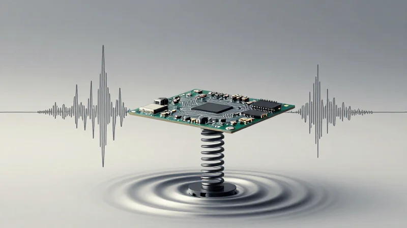
In high-vibration zones, the primary cause of transmission control unit (TCU) failure is not electrical noise, but mechanical fatigue leading to intermittent connectivity. To maintain signal integrity, the PCB layout must decouple the mechanical stress of the chassis from the sensitive interconnects, utilizing rigid-flex transitions and localized stiffening to prevent board flexing that fractures solder joints.
Mechanical Decoupling and Solder Joint Protection
Mechanical damping is vital for high-performance TCUs. By employing heavy copper cladding and strategic placement of mounting holes, engineers can increase the resonant frequency of the PCB, pushing it beyond the operational vibration spectrum of the transmission assembly. Furthermore, the use of underfill materials on large BGA components is mandatory to distribute strain uniformly across the solder balls, preventing thermal expansion and vibration-induced shearing.
| Strategy | Primary Benefit | Implementation Note |
|---|---|---|
| BGA Underfill | Stress Distribution | Essential for high-I/O count processors. |
| Localized Stiffening | Flexure Mitigation | Utilize FR-4 stiffeners near high-mass connectors. |
| Solder Mask Defined (SMD) Pads | Pad Integrity | Improve pad adhesion to the board surface. |
Optimizing Connector Integrity
Connectors represent the most significant failure points in high-vibration environments. Employing through-hole press-fit technology is preferred over surface-mount headers for high-current and data-critical interfaces. Press-fit technology offers a gas-tight, cold-weld connection that is inherently more resistant to micro-vibrations than traditional solder fillets, which are prone to work-hardening and fracture over time.
Frequently Asked Questions
- How does PCB thickness influence vibration resilience?
Increased thickness enhances the board's stiffness-to-weight ratio, effectively shifting the natural resonant frequency of the assembly away from the dominant vibration frequencies found in engine/transmission systems. - Why is component orientation critical?
Components should be oriented such that their longest axis is parallel to the primary axis of board flexure, minimizing the leverage forces exerted on individual solder joints.
Selecting Surface Finishes for Chemical Resistance
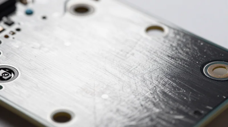
In TCU design, the surface finish is the final line of defense against oxidation, sulfur-induced corrosion, and chemical degradation. Because automotive environments often introduce harsh contaminants—including salt spray, humidity, and automotive fluids—the choice of finish must balance solderability with long-term chemical robustness.
Comparative Analysis of Surface Finishes
| Finish | Chemical Robustness | Oxidation Resistance | Best Application |
|---|---|---|---|
| ENIG | High | Excellent | High-reliability signal integrity |
| Immersion Silver | Moderate | Low (Susceptible to Creep Corrosion) | Cost-sensitive consumer-grade |
| ENEPIG | Superior | Exceptional | Extreme automotive/aerospace |
| HASL (Lead-Free) | Low | Good | Non-fine pitch industrial |
Engineering Considerations for Harsh Environments
- Why is Creep Corrosion a major concern for Immersion Silver?
Immersion Silver is highly susceptible to sulfur-based creep corrosion, which causes dendrite growth across traces when exposed to automotive gases, leading to short circuits. - Why is ENEPIG preferred over standard ENIG for TCU boards?
ENEPIG adds a palladium layer between the nickel and gold. This prevents 'black pad' issues and provides a more robust barrier against chemical permeation in high-vibration and thermal-shock environments. - How does surface finish affect solder joint integrity?
Consistent wetting and the avoidance of brittle intermetallic compounds are essential; ENIG and ENEPIG provide superior planar surfaces compared to HASL, which is crucial for modern fine-pitch components.
Engineers must prioritize ENEPIG or high-quality ENIG for TCU systems. While cost-saving measures like Immersion Silver or OSP are tempting, the life-cycle cost of field failures due to chemical oxidation significantly outweighs the initial assembly savings.
Design for Manufacturing (DFM) for Automotive Reliability
In the context of high-performance TCU PCBs, DFM is not merely about production efficiency; it is a fundamental pillar of automotive reliability. By optimizing board layout, component placement, and material selection for manufacturability, engineers can significantly reduce latent defects caused by thermal fatigue, soldering stress, and chemical exposure. A robust DFM approach ensures that the design intent is perfectly replicable under rigorous mass-production conditions, maintaining signal integrity and structural stability over the vehicle's entire lifecycle.
Key DFM Optimization Principles
- Panelization and Throughput
Utilize optimized panel layouts to minimize material waste while ensuring structural support for heavy components, which prevents board warping during high-temperature reflow cycles. - Component Orientation
Align surface-mount components relative to the solder wave or reflow direction to reduce shadow effects and prevent solder bridging, ensuring consistent interconnect strength. - Thermal Relief Consistency
Apply uniform thermal relief patterns to all pads connected to internal ground or power planes to prevent uneven heating and cold solder joints during automated assembly. - Trace Geometry Control
Avoid acute angles in trace routing to minimize stress concentrations and prevent acid traps during the chemical etching process, which can lead to long-term latent open circuits.
Manufacturing Constraint Comparison
| Parameter | Standard Industrial | High-Reliability Automotive |
|---|---|---|
| Copper Weight Tolerance | +/- 10% | +/- 5% (Controlled Impedance) |
| Via Drill Precision | Standard CNC | Laser-drilled for aspect ratio control |
| Annular Ring Requirements | Minimal IPC Class 2 | Enhanced IPC Class 3 standards |
| Panel Warpage Limit | 0.75% | 0.50% (Maximized for SMT) |
DFM Best Practices for TCU Reliability
To achieve high-reliability, engineers must prioritize the prevention of micro-cracking and interfacial delamination. This involves designing specific land patterns that account for CTE (Coefficient of Thermal Expansion) mismatches between the PCB substrate and large components like power MOSFETs. Incorporating rounded fillets and ensuring adequate spacing for conformal coating coverage are critical steps in protecting against harsh under-the-hood environmental ingress.
Selecting the right PCB materials and thermal strategies is the foundation of a reliable TCU that can stand the test of time and terrain. By prioritizing material integrity and rigorous testing standards, you ensure your vehicle systems maintain peak performance throughout their entire operational life. Ready to upgrade your automotive design strategy? Contact our engineering team today to discuss your next high-performance PCB project.
