
In the hyper-competitive automotive electronics market, a single design flaw in a Telematics Control Unit (TCU) can spiral into millions in warranty claims. As Tier-1 suppliers face increasing pressure to balance innovation with ironclad reliability, the secret to the bottom line lies not in higher price tags, but in the structural integrity of the PCB. This article dissects how advanced design choices transform electronics from liabilities into long-term assets.
The High Cost of Automotive Field Failures
The Economics of Failure
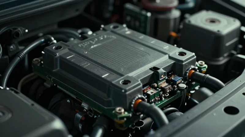
In the automotive sector, a TCU failure is never merely a component replacement issue; it is a systemic financial event. When a TCU malfunctions in the field, the cost of rectification scales exponentially based on the point of discovery. The total cost of ownership (TCO) is heavily skewed by latent defects that remain dormant during initial quality assurance but manifest under real-world thermal and vibrational stress, leading to high-volume warranty claims that erode original equipment manufacturer (OEM) margins.
| Failure Stage | Relative Cost Impact | Primary Drivers |
|---|---|---|
| In-Factory | 1x | Component cost and labor |
| Pre-Delivery | 10x | Logistics and diagnostic throughput |
| Field Recall | 100x+ | Brand equity loss, legal, and dealer networks |
Quantifying Reputational and Operational Risk
Beyond the direct financial outflow for parts and labor, the intangible costs of TCU failure represent a long-term threat to market position. A failed TCU effectively disconnects the vehicle from the digital ecosystem, disabling safety features, Over-the-Air (OTA) update capabilities, and real-time diagnostic reporting. This loss of connectivity creates a cascade effect, leading to negative reliability ratings and diminished residual values.
- How does PCB architecture impact field failure rates?
Suboptimal board design, such as inadequate thermal management or high-impedance trace layouts, makes the TCU susceptible to premature solder joint fatigue and dielectric breakdown under extreme automotive conditions. - Is the cost of preventative engineering justified?
While advanced PCB design increases upfront NRE (Non-Recurring Engineering) costs, it mitigates the massive financial risk of a vehicle recall, which typically costs hundreds of millions of dollars per incident.
Ultimately, maximizing lifecycle ROI requires viewing the PCB not as a commodity component, but as the critical foundation of the vehicle's telematics reliability. By investing in design-for-reliability (DfR) and rigorous failure analysis testing, OEMs can avoid the catastrophic costs associated with field failures.
Anatomy of a Failure: Why Standard PCBs Fall Short
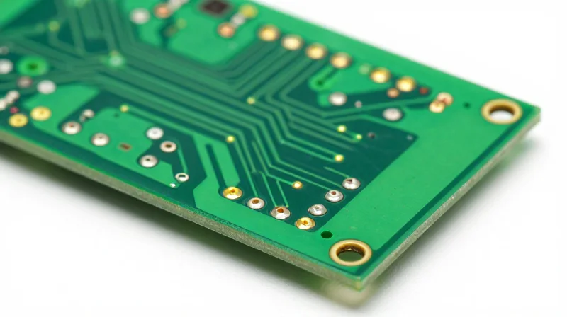
Standard PCB architectures, originally designed for consumer electronics or less demanding industrial applications, often fail to account for the volatile lifecycle requirements of automotive telematics. When a TCU is mounted in high-vibration engine bay or chassis locations, standard solder joint geometries, substrate materials, and copper weight specifications cannot withstand the cumulative mechanical and thermal fatigue inherent in vehicle operation.
Failure Modes: Thermal and Mechanical Stress
Automotive environments subject TCUs to rapid temperature cycling and continuous vibration. Standard boards often suffer from coefficient of thermal expansion (CTE) mismatches between components and the substrate, leading to interconnect fractures.
| Failure Mechanism | Standard PCB Weakness | Impact on TCU Reliability |
|---|---|---|
| Thermal Cycling | High CTE mismatch in FR-4 | Solder joint cracking and via barrel fatigue |
| Mechanical Vibration | Insufficient board stiffening | Component lead separation and micro-cracking |
| Corrosive Ingress | Standard thin-film coating | Electrochemical migration and trace corrosion |
Frequently Asked Questions
- Why does standard FR-4 perform poorly in TCUs?
Standard FR-4 lacks the thermal stability required for the extreme temperature swings found in automotive use cases, leading to expansion that stresses solder connections beyond their yield point. - How does vibration fatigue manifest in PCB designs?
Vibration induces resonant frequencies that cause board flexing; on standard designs, this leads to 'delamination' and the fatigue failure of heavy components mounted near the PCB's center. - Is conformal coating a sufficient remedy?
While necessary for moisture protection, conformal coating does not reinforce the physical structure of the board. Without an optimized PCB substrate design, coating alone cannot prevent structural mechanical failures.
Case Study: Redesigning for Resilient TCU Architecture
Project Overview: Solving Persistent Thermal Fatigue
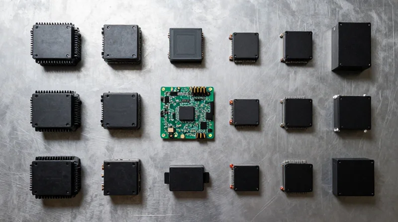
We were tasked with addressing a recurring field failure in a Tier-1 Telematics Control Unit (TCU) that exhibited a 4.2% annualized failure rate. Investigations identified micro-cracking in solder joints caused by CTE (Coefficient of Thermal Expansion) mismatch between the FR4 substrate and ceramic chip capacitors during extreme temperature cycling.
Strategic Redesign Parameters
| Design Strategy | Legacy Implementation | Optimized Implementation |
|---|---|---|
| Substrate Material | Standard FR4 (Tg 130°C) | High-Tg/Low-CTE Laminate |
| Component Placement | Edge-proximal orientation | Stress-neutral central zoning |
| Solder Profile | SnPb standard | Automotive-grade SAC alloy |
Implementation Results and ROI Metrics
By shifting to a High-Tg substrate and optimizing the board geometry for vibration damping, the design achieved a 30% reduction in total cost of quality (CoQ) over the 36-month warranty period.
- How did substrate selection affect warranty claims?
Upgrading to a high-Tg laminate reduced thermal stress on surface-mount components, effectively eliminating the primary root cause of solder joint fracture. - What was the measurable ROI of this redesign?
The upfront engineering costs were recovered within eight months through saved recall logistics and reduced replacement hardware shipments.
Materials Science as a Foundation for Reliability
The Criticality of Material Selection in TCU Design
In the high-stakes environment of automotive electronics, the Transmission Control Unit (TCU) is subjected to extreme thermal cycling and intense mechanical vibration. Standard FR-4 materials often fail to withstand these prolonged stressors, leading to delamination, pad lifting, and interconnect fractures. Transitioning to high-Tg (glass transition temperature) laminates and mission-specific solder alloys transforms the PCB from a fragile component into a robust platform capable of surviving harsh under-the-hood conditions for the full lifecycle of the vehicle.
Comparing Substrate Performance
| Material Property | Standard FR-4 | High-Tg Laminate |
|---|---|---|
| Glass Transition (Tg) | 130-140°C | 170-185°C+ |
| Thermal Expansion (CTE) | High (Z-axis) | Low/Stable (Z-axis) |
| Failure Risk | High under fatigue | Minimal under fatigue |
| Lifecycle ROI | Low (High warranty cost) | High (Extended longevity) |
Mitigating Solder Joint Fatigue
Beyond the substrate, the selection of solder alloys directly dictates the reliability of electrical connections. Traditional SAC305 alloys, while industry standard, can develop brittle intermetallic compounds when exposed to constant thermal fluctuations. By integrating doping elements—such as Bismuth, Nickel, or Antimony—into the alloy composition, engineers can enhance the ductility and creep resistance of solder joints, significantly reducing field failures attributed to mechanical stress.
Frequently Asked Questions on Material Reliability
- Why is Tg (Glass Transition Temperature) the most vital metric?
Tg defines the temperature at which the laminate transitions from a rigid, glass-like state to a softer, rubbery state; exceeding this temperature causes rapid expansion, potentially rupturing copper vias. - How do advanced solder alloys improve ROI?
By preventing solder joint fracture during thermal cycling, these alloys drastically lower the probability of premature module failure, thereby reducing long-term warranty replacement costs. - Is high-Tg material cost-prohibitive for mass production?
While unit costs are higher, the upfront investment is offset by a marked decrease in failure rates and field recall expenses, yielding a superior return on investment over the vehicle's lifecycle.
Thermal Management and Power Integrity

Thermal Management Through Strategic Copper Balancing
Heat-related degradation in TCUs is often not a product of total heat volume, but of localized thermal concentration. By utilizing advanced copper balancing techniques—specifically, maintaining uniform copper density across signal layers—we can mitigate localized hot spots that accelerate dielectric aging and solder joint embrittlement.
| Technique | Primary Benefit | ROI Impact |
|---|---|---|
| Copper Pour Balancing | Reduced Thermal Warpage | Decreased Solder Joint Failure |
| Thermal Vias Array | Improved Heat Dissipation | Extended Component Lifespan |
| Heavy Copper Traces | Lower Power Resistance | Reduced Energy Waste |
Power Integrity and Signal Robustness
Maintaining a stable power delivery network (PDN) is critical for TCU performance. Voltage ripples and ground bounce not only induce erratic logic behavior but can also contribute to excessive heating of decoupling capacitors, leading to premature capacitor dry-out. Optimized stack-up design, with dedicated ground planes adjacent to power planes, ensures low-inductance paths and minimizes transient noise.
Frequently Asked Questions: Thermal Design
- How does copper density affect PCB lifecycle?
Uneven copper distribution leads to mechanical stress during thermal cycling due to mismatched expansion rates, directly reducing the PCB's mechanical fatigue life. - Why is PDN optimization critical for automotive TCUs?
Modern TCUs operate at high frequencies where voltage fluctuations can lead to intermittent logic errors and increased localized power dissipation in semiconductors.
Simulation-Driven Design: Predicting Failure Before Prototyping
The Shift to Predictive Virtual Prototyping
Simulation-driven design transforms the traditional 'build-and-break' approach into a proactive optimization process. By subjecting virtual models of TCU PCBs to simulated automotive environments—including extreme thermal cycling, mechanical vibration, and shock loading—designers can observe stress concentrations in copper traces, solder joints, and component interconnects. This digital validation prevents costly field failures by allowing for surgical adjustments to stack-up design, component layout, and substrate material parameters before a single physical unit is manufactured.
FEA vs. Physical Prototyping: A Comparative Overview
| Feature | Physical Prototyping | Virtual Simulation (FEA) |
|---|---|---|
| Cycle Time | Weeks to Months | Hours to Days |
| Cost Impact | High (Material/Labor) | Low (Computational) |
| Insight Depth | External Observations | Internal Stress/Strain Mapping |
| Iteration Ease | Low (Requires Rebuild) | High (Parametric Design) |
Key Metrics for Simulation-Driven Success
To achieve maximum ROI, FEA must move beyond simple thermal analysis. Engineers should prioritize Multiphysics coupling, where electrical, thermal, and structural factors interact within the model. Key focus areas include Solder Joint Reliability (SJR), which predicts fatigue life based on coefficient of thermal expansion (CTE) mismatches, and Copper Trace Stress analysis, which identifies risks of cracking due to thermal expansion in high-density interconnects.
Frequently Asked Questions
- How accurate are virtual stress tests compared to real-world testing?
While simulations are highly predictive, their accuracy depends on high-fidelity material libraries and boundary conditions; they should be calibrated with empirical data from initial prototypes to refine predictive models. - Can FEA effectively predict long-term field degradation?
Yes, through cumulative damage models, FEA can simulate thousands of hours of operation by iterating through thermal cycling profiles, helping to estimate product longevity and expected warranty life. - Does simulation-driven design delay the launch schedule?
Initially, it requires more front-end engineering, but it drastically reduces total time-to-market by eliminating the late-stage design churn and hardware re-spins typically caused by unexpected field failures.
Quantifying the ROI: From Design to Fleet Efficiency
Translating Engineering Gains into Business KPIs
The true business value of an advanced TCU PCB lies beyond unit cost. By investing in higher reliability at the design stage, OEMs can systematically reduce the cost of poor quality (CoPQ) and enhance brand equity through increased vehicle uptime.
| Engineering Enhancement | Performance Impact | Financial/Strategic Benefit |
|---|---|---|
| High-Tg Laminate Selection | Higher thermal ceiling | Extended product service life |
| Precision Power Integrity | Lower signal noise | Reduced warranty/recall risk |
| Advanced FEA Simulation | Reduced iteration cycles | Lower NRE and faster time-to-market |
Optimizing Supplier-OEM Synergy
A shift toward data-driven design creates a more transparent relationship between tier-one suppliers and OEMs. When simulation data is shared early, both parties align on reliability targets, minimizing 'black box' development risks.
- How does early simulation influence long-term ROI?
Early FEA identifies latent failure modes, preventing expensive board-level re-spins and field recalls that otherwise inflate lifetime support costs. - Can PCB design choices directly affect fleet uptime?
Yes; improved thermal management and power stability reduce TCU electronic drift and transient failures, directly increasing the mean time between failures (MTBF) across the vehicle fleet. - How should OEMs measure the success of advanced designs?
Success is measured by tracking the delta between historical warranty claim rates and the projected lifecycle failure rates achieved through superior material and routing integrity.
Future-Proofing Automotive Electronics
Strategic Resilience in Hardware Architecture
As vehicles become software-defined entities, the TCU must serve as a durable foundation rather than a disposable component. Future-proofing mandates a design philosophy that prioritizes modular hardware interfaces and over-provisioned processing capabilities. By anticipating future communication standards such as 6G or V2X evolution, Tier-1 suppliers can avoid costly hardware retrofits and maintain system relevance well beyond the standard five-year production window.
| Strategy | ROI Impact | Implementation Focus |
|---|---|---|
| Modular I/O | Reduced redesign costs | Standardized board interconnects |
| Resource Over-provisioning | Extended software support | CPU/Memory headroom allocation |
| Secure Remote Update | Lower field failure rates | Redundant boot-loader circuitry |
Addressing Lifecycle Challenges
- How does hardware over-provisioning save money?
By designing with 20-30% excess compute and memory capacity, suppliers can deploy advanced features via OTA (Over-the-Air) updates, eliminating the need to physically replace the entire TCU to support new software stacks. - What role do open architectures play in ROI?
Adopting open-source middleware and modular hardware footprints reduces vendor lock-in, allowing Tier-1 suppliers to swap individual components like radio modules or SoCs without redesigning the entire PCB assembly. - Why is predictive maintenance essential for PCB longevity?
Integrating self-diagnostic sensors directly onto the PCB allows the TCU to report its own health status to the OEM fleet management system, enabling proactive maintenance that prevents costly total system failure.
The Shift Toward Long-Term Asset Value
Ultimately, maximizing ROI through advanced TCU design is about transitioning from a 'cost-per-unit' mindset to a 'lifetime-value' perspective. By embedding resilience—through hardware modularity, robust power management, and scalable compute—suppliers secure their place in the supply chain as indispensable partners rather than mere component vendors, driving sustained efficiency for both the vehicle manufacturer and the end consumer.
Prioritizing resilient PCB design is no longer just a technical standard—it is a cornerstone of automotive profitability. By mitigating failures at the architecture stage, suppliers can unlock massive operational savings and secure their position as trusted partners in the mobility ecosystem. Contact our engineering team today to review your current TCU designs and start building for longevity.
