
In the precision-driven world of dental imaging, the integrity of your high-voltage circuitry is not just a performance metric—it is a cornerstone of patient safety and equipment longevity. Selecting the right PCB manufacturer requires a deep dive into technical expertise and rigorous quality compliance.
Understanding the High-Voltage Demands of Dental Imaging
The Challenge of Extreme Electrical Stress
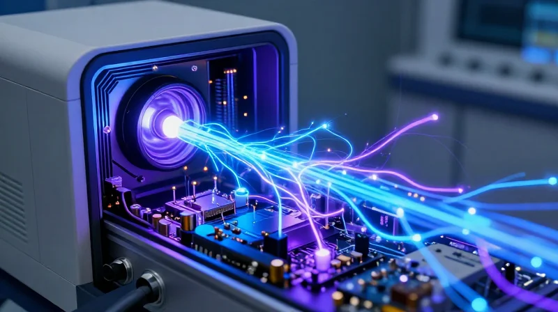
Dental X-ray systems operate on a fundamental trade-off: they require high-energy photon generation while maintaining a compact form factor. This creates a challenging environment where PCBs must manage high-voltage DC potentials—often exceeding 70kV—within confined spaces. The primary engineering challenge is preventing partial discharge and dielectric breakdown, which are accelerated by the high-frequency switching required to maintain image clarity and reduce patient radiation exposure.
Key Failure Modes in High-Voltage Environments
- Dielectric Breakdown
Occurs when the insulating material between traces is insufficient for the voltage potential, leading to permanent structural failure and carbon tracking. - Corona Discharge
High-voltage air ionization around sharp solder points or trace edges, which degrades surface materials and causes electromagnetic interference in sensitive sensor data paths. - Thermal Cycling Fatigue
The rapid expansion and contraction of board materials during high-load imaging pulses can weaken solder joints and lead to delamination.
Material Selection Criteria
| Feature | Requirement for Dental HV-PCB | Justification |
|---|---|---|
| Dielectric Constant (Dk) | Low and Stable | Minimizes signal attenuation at high pulse frequencies. |
| Comparative Tracking Index (CTI) | High (>600V) | Prevents short circuits across the board surface. |
| Glass Transition (Tg) | High (>170°C) | Ensures dimensional stability under rapid thermal pulses. |
Engineers must prioritize materials that demonstrate a high resistance to conductive anodic filament (CAF) growth. In dental applications, the integration of high-voltage transformers and high-speed data acquisition on a single or adjacent board architecture necessitates strict spacing and superior conformal coating strategies. Failure to account for these electrical stresses in the procurement stage frequently leads to field reliability issues, necessitating costly recalls for complex medical hardware.
Mandatory Compliance: ISO 13485 and Medical Standards
Why ISO 13485 is Non-Negotiable
In the medical device industry, ISO 13485 serves as the gold standard for quality management systems (QMS). When procuring high-voltage PCBs for dental imaging, choosing a manufacturer without this certification exposes your project to severe regulatory risks and potential market entry failures. ISO 13485 mandates rigorous traceability, document control, and risk management processes specifically designed to minimize hazards associated with critical medical electronics.
Comparison of Manufacturing Standards
| Feature | Standard ISO 9001 | Medical ISO 13485 |
|---|---|---|
| Risk Management | General focus | Product-specific clinical safety |
| Traceability | Standard lot tracking | Unique Device Identification (UDI) |
| Regulatory Focus | Business quality | Patient safety and efficacy |
| Change Control | Documentary only | Impact assessment on clinical performance |
Key Regulatory Considerations for High-Voltage Components
- How does ISO 13485 affect PCB component selection?
Certified manufacturers must enforce strict AVL (Approved Vendor List) controls, ensuring that high-voltage capacitors and transformers meet verified safety standards for medical-grade isolation. - What is the role of traceability in an audit?
In the event of a field failure, ISO 13485 requires the ability to map every high-voltage PCB back to its exact raw material batch and assembly operator, which is essential for FDA or MDR compliance audits. - Does ISO 13485 guarantee electrical safety?
While it focuses on QMS, it ensures that your internal design controls regarding creepage and clearance distances are validated and documented, preventing catastrophic arcing in X-ray generators.
Engineers must view ISO 13485 not as a bureaucratic hurdle, but as a technical safeguard. By partnering with a certified supplier, you effectively integrate their quality culture into your design cycle, mitigating the risks inherent in high-voltage dental X-ray imaging components.
Selecting Substrate Materials for Arc Resistance

In dental X-ray systems, where voltages often exceed 60-70kV, standard FR-4 substrates are often insufficient to prevent tracking, surface carbonization, and catastrophic dielectric failure. Selecting materials with a high Comparative Tracking Index (CTI) is mandatory to ensure longevity and patient safety.
Prioritizing Comparative Tracking Index (CTI)
The CTI value represents the voltage threshold at which a material fails under controlled test conditions. For high-voltage imaging electronics, procurement engineers must specify laminates rated at CTI 600V or higher to provide a sufficient safety margin against electrical tracking across the board surface in the presence of humidity or contaminants.
| Material Category | Typical CTI Rating | Suitability for X-Ray High Voltage |
|---|---|---|
| Standard FR-4 | 175-250V | Unsuitable (High Risk) |
| High-CTI FR-4 | 600V+ | Acceptable for Secondary Circuits |
| Polyimide / Specialized Ceramics | 600V+ | Recommended for HV Generation Stages |
Critical Material Selection Factors
- Why is moisture absorption a key metric?
Materials that absorb moisture lower their effective dielectric strength, creating conductive paths that lead to arcing; always specify low-moisture absorption laminates. - Does glass transition temperature (Tg) matter?
Yes, high Tg materials maintain dimensional stability and mechanical strength under the thermal stresses generated by repeated X-ray exposure cycles. - Should I consider ceramic-filled laminates?
Ceramic-filled composites offer superior thermal conductivity and inherent arc resistance compared to standard resin-based systems, making them ideal for high-stress voltage multiplication stages.
By prioritizing materials with superior electrical tracking resistance and environmental stability, engineers can significantly reduce the risk of field failures, ensuring the reliability required for diagnostic-grade dental imaging equipment.
Advanced Thermal Management Strategies
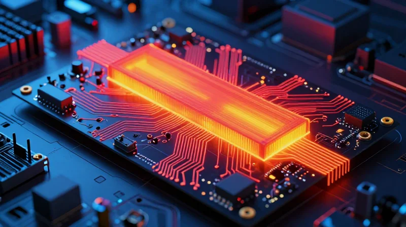
In dental X-ray applications, high-voltage generation produces localized heat at the switching nodes and high-frequency transformers. Without robust thermal dissipation, the dielectric integrity of the PCB substrate decreases, significantly increasing the probability of carbon tracking and catastrophic arcing. Procurement engineers must ensure manufacturers employ a multi-layered approach to heat management that balances thermal conductivity with high-voltage clearance requirements.
Evaluation Criteria for Thermal Dissipation Techniques
| Thermal Strategy | Key Procurement Metric | Impact on High-Voltage Stability |
|---|---|---|
| Thermal Vias | Array Density & Plating | Reduces junction temperature of power MOSFETs. |
| High-Conductivity Substrates | Thermal Conductivity (W/mK) | Dissipates heat away from critical high-voltage traces. |
| Integrated Heat Sinks | Bondline Thermal Resistance | Prevents thermal runaway during pulsed imaging cycles. |
Thermal Management Best Practices
- Optimizing Thermal Via Arrays
Ensure the manufacturer uses copper-filled vias rather than standard tenting to maximize thermal path conductivity while maintaining dielectric isolation. - Selecting High-Conductivity Substrates
Prioritize substrates with high glass transition temperatures (Tg) and high thermal conductivity ratings to maintain structural stability under high-voltage load. - Evaluating Thermal Interface Materials (TIM)
Verify that all TIMs used between power components and heat sinks are rated for high-voltage dielectric breakdown to prevent leakage currents.
When auditing a supplier, demand thermal simulation reports (e.g., Ansys or FloTHERM) specific to your board layout. A capable manufacturer will demonstrate how their thermal via placement does not compromise creepage and clearance distances, which are vital for safety in dental radiography systems.
Design for Manufacturing (DFM) for High-Voltage Safety

DFM Principles for High-Voltage Reliability
Effective DFM for dental X-ray systems must prioritize the prevention of electrical breakdown. Engineers must mandate strict adherence to international safety standards like IEC 60601-1 to ensure creepage and clearance distances are optimized for the specific operating voltages of the X-ray tube.
Critical Arc Prevention Parameters
| Parameter | Design Objective | DFM Requirement |
|---|---|---|
| Creepage | Prevent surface tracking | Ensure path follows insulating surface profile |
| Clearance | Prevent air ionization | Maximize shortest air gap distance |
| Edge Spacing | Avoid edge breakdown | Internalize high-voltage traces |
Beyond basic spacing, conformal coating and edge milling are critical. Conformal coatings provide a secondary dielectric barrier, while routed slots between high-voltage nodes significantly increase the effective creepage path without expanding the board footprint.
Frequently Asked Questions
- Why are board edge clearances critical in high-voltage designs?
The edges of a PCB are susceptible to contaminants and moisture, which reduce dielectric strength; moving high-voltage traces away from the edge prevents arcing to the chassis. - How does conformal coating improve DFM performance?
A high-quality conformal coating creates a non-conductive, moisture-resistant barrier that protects against environmental contamination, essentially increasing the effective dielectric breakdown strength. - What is the role of routing slots in PCB design?
Routing slots or 'air gaps' increase the physical creepage distance between conductors, which is essential when space constraints prevent the horizontal spacing required by standard regulations.
Quality Control and Advanced Testing Protocols
The Necessity of Stringent Testing in High-Voltage Environments
In dental X-ray systems, even minor microscopic defects in the PCB fabrication or assembly process can lead to catastrophic arcing or system failure under high-voltage loads. Engineers must mandate a comprehensive validation suite that moves beyond standard functional testing to include structural integrity, dielectric strength, and long-term environmental stress screening.
Critical Inspection and Verification Methods
| Testing Protocol | Primary Objective | Significance for X-Ray Systems |
|---|---|---|
| Automated Optical Inspection (AOI) | Surface geometry verification | Ensures precise solder joints and component placement to prevent localized field concentration. |
| Automated X-Ray Inspection (AXI) | Internal void detection | Identifies hidden solder voids in BGA packages that could become flashover points. |
| High-Potential (Hipot) Testing | Dielectric integrity | Confirms the board withstands specific peak voltages without leakage or catastrophic discharge. |
Procurement Frequently Asked Questions
- Why is Hipot testing performed at the sub-assembly level?
Testing before and after final enclosure installation ensures that no mechanical stress during assembly has compromised the board’s isolation barriers or increased the risk of partial discharge. - How does AXI improve high-voltage reliability?
AXI detects sub-surface solder voids in high-power components. In high-voltage circuits, these microscopic voids can act as ionizable pockets that trigger corona discharge, eventually leading to board carbonization and failure. - Should manufacturers provide raw test data?
Yes. Engineers should require standardized test reports including leakage current values and pass/fail thresholds to verify the manufacturer adheres to IEC 60601-1 safety standards for medical electrical equipment.
Environmental Stress Screening (ESS)
To guarantee longevity, select suppliers that perform Thermal Cycling or Accelerated Life Testing (ALT). By subjecting boards to rapid temperature transitions under operational voltage, manufacturers can precipitate early-life failures (infant mortality) caused by mismatched coefficients of thermal expansion between the substrate, copper layers, and protective conformal coatings.
Supply Chain Transparency and Long-Term Support
Ensuring Supply Chain Continuity
The long product lifecycle of dental X-ray systems demands a stable supply chain to avoid costly redesigns caused by component obsolescence. Procurement engineers must prioritize manufacturers who provide full traceability, proactive end-of-life (EOL) notifications, and robust inventory management strategies.
| Supply Chain Metric | Low-Risk Indicator | High-Risk Indicator |
|---|---|---|
| Traceability | Full lot-level documentation | Opaque sourcing |
| EOL Notification | 12+ months lead time | No notification process |
| Inventory Strategy | Safety stock for critical ICs | Just-in-time reliance |
Manufacturer Stability and Support
A reliable partner does more than manufacture boards; they provide sustained engineering support. This includes technical collaboration during the entire lifecycle, from prototyping to field maintenance and potential hardware revisions.
- How can I verify a manufacturer's commitment to long-term support?
Review their history of supporting legacy designs and request an explicit obsolescence management policy that guarantees notification periods of at least one year. - Why is component traceability critical for dental X-ray systems?
Regulatory compliance (such as FDA or CE medical standards) requires strict documentation of every component used in the device to ensure safety and facilitate rapid resolution in the event of field failures. - Does the manufacturer offer post-production engineering support?
Top-tier partners provide dedicated support teams to assist with hardware debugging, component substitution analysis, and firmware integration long after the initial production run.
The Final Selection Checklist for Engineers
The Engineering Procurement Audit Matrix
Before finalizing a partnership for high-voltage PCB manufacturing, engineers must verify that the vendor possesses the specific technical infrastructure to handle the rigors of dental imaging hardware. Use the following criteria to evaluate prospective suppliers during the final selection phase.
| Evaluation Pillar | Critical Verification Point | Acceptance Criterion |
|---|---|---|
| High-Voltage Design | Creepage & Clearance | Meets IPC-2221/9592 standards |
| Manufacturing | Process Control | Certified ISO 13485 (Medical) |
| Testing | Dielectric Integrity | 100% Hipot testing capability |
| Logistics | BOM Management | Obsolescence mitigation policy |
Final Selection Checklist: Vendor Capabilities
- Certification Verification
Confirm the facility is ISO 13485 certified specifically for medical device manufacturing, not just general-purpose PCB assembly. - Cleanliness Standards
Ensure ionic contamination levels are strictly monitored, as residues can lead to electrochemical migration and dielectric breakdown at high voltages. - HV Testing Infrastructure
Request documentation of their high-potential (hipot) testing equipment and verify it matches the peak voltage requirements of your X-ray generator. - Supply Chain Stability
Ask for a documented component life-cycle strategy. Are they tracking 'End-of-Life' (EOL) components for your specific BOM? - DFM Review Process
Verify that their engineering team actively provides feedback on your gerber files regarding arc prevention and board edge clearance before fabrication begins.
Finalizing a vendor for high-voltage applications is a high-stakes decision. The audit should culminate in a site visit or a thorough virtual inspection where you witness the handling of sensitive materials and the specific quality control stations assigned to your project. By adhering to this checklist, you minimize the risk of field failures, which are particularly catastrophic in dental clinical environments.
Selecting a PCB manufacturer for your dental imaging systems is a strategic decision that impacts your product's safety, reliability, and market reputation. By prioritizing stringent compliance and advanced material science, you protect your users and your bottom line. Contact our engineering team today to audit your PCB procurement requirements and ensure your next project meets the highest medical standards.
