
In the rapidly evolving world of electric vehicles, the demand for power density in inverter systems has never been higher. Engineers are pushed to maximize thermal efficiency while adhering to zero-failure safety standards. Choosing the wrong PCB manufacturer can lead to catastrophic thermal runaway or field failures. This guide provides an authoritative framework for evaluating manufacturing partners equipped to handle the extreme rigors of automotive high-power electronics.
Understanding the Unique Demands of Automotive Power Electronics
The Challenge of High-Power Density
As electric vehicles (EVs) migrate toward 800V architectures and higher power densities, the power electronics—specifically inverters—are subjected to unprecedented thermal and electrical stress. Traditional PCB standards are insufficient for managing the high current loads and potential localized heating inherent in these systems. Heavy copper PCBs act as the foundational thermal management layer, requiring precise material selection, structural integrity, and manufacturing rigor to ensure the longevity and safety of the vehicle.
Performance Requirements Comparison
| Requirement | Consumer Electronics PCB | Automotive Inverter PCB |
|---|---|---|
| Copper Thickness | 1 oz - 2 oz | 3 oz - 20+ oz |
| Thermal Management | Passive cooling | High thermal mass/Active integration |
| Reliability Standard | Standard IPC Class 2 | IPC Class 3 / Automotive Grade |
| Current Load | Low/Signal | High Amperage Power Delivery |
Critical Reliability Factors
- How does copper thickness affect inverter reliability?
Increased copper thickness directly lowers the electrical resistance of the trace, reducing I²R power dissipation (Joule heating). This allows the board to handle extreme currents without failing due to thermal overload or copper trace delamination. - Why is thermal expansion management crucial in automotive PCBs?
Automotive inverters experience rapid, repeated thermal cycling. The coefficient of thermal expansion (CTE) mismatch between thick copper, FR4 substrate, and solder joints causes mechanical fatigue, which can lead to micro-cracks and system failure over time. - What manufacturing precision is required for heavy copper?
Etching thick copper is inherently difficult, often leading to uneven trace sidewalls or undercutting. A qualified manufacturer must ensure precise edge definition to prevent signal noise, impedance irregularities, and insulation degradation.
The Importance of Copper Weight Consistency
The Direct Impact of Copper Weight Variance
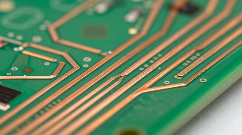
In heavy copper PCBs designed for high-power automotive inverters, the copper weight determines the cross-sectional area of the conductor. Even minor, uncontrolled variances in copper thickness lead to unpredictable resistance levels. When copper weight is inconsistent, the localized current density increases at thinner regions, creating 'hot spots' that degrade the substrate and compromise long-term structural integrity under cyclic thermal stress.
Critical Performance Impacts
| Parameter | Effect of Copper Variance | Consequence |
|---|---|---|
| Current Capacity | Thinner sections create bottlenecks | Overtemperature failures |
| Impedance | Deviations from nominal thickness | Signal mismatch/noise |
| Thermal Dissipation | Inconsistent heat spreading paths | Thermal runaway risks |
Frequently Asked Questions
- How does copper thickness affect impedance matching?
Impedance is a function of the trace geometry and dielectric constant. If the copper etching process is inconsistent, the trace width and thickness vary, shifting the characteristic impedance and causing signal reflections that destabilize high-frequency gate drive signals. - What manufacturing tolerance should be expected for heavy copper?
Precision manufacturers typically adhere to IPC-6012 standards, aiming for tight tolerances on finished copper weight. For critical automotive applications, manufacturers must demonstrate tight process control over plating uniformity across the entire panel surface. - Can inconsistent copper cause mechanical failure?
Yes. Non-uniform copper distribution leads to uneven coefficient of thermal expansion (CTE) stresses during power cycling, which can induce micro-cracking in the PCB laminate or inter-layer vias.
Thermal Management Capabilities and Material Selection
Substrate Engineering for Extreme Environments
Automotive power inverters generate significant thermal loads, necessitating the use of high-Glass Transition Temperature (high-Tg) laminates. Standard FR-4 materials frequently fail due to thermal fatigue and delamination when exposed to continuous high-current cycles. Manufacturers must prioritize substrates with a Tg greater than 170°C and a low Coefficient of Thermal Expansion (CTE), ensuring mechanical integrity across wide temperature swings common in under-hood environments.
Thermal Management Strategies
Managing heat dissipation in heavy copper systems requires more than just conductive traces; it demands an integrated architectural approach. The following table highlights common techniques employed to optimize thermal impedance.
| Thermal Technique | Primary Benefit | Implementation Priority |
|---|---|---|
| Thermal Vias | Vertical heat transport to heatsink | Critical |
| Embedded Heat Sinks | Direct interface with high-power components | High |
| Metal Core (IMS) | Superior dielectric thermal conductivity | High |
| Thick Copper Planes | Heat spreading across the PCB surface | Standard |
Frequently Asked Questions on Thermal Reliability
- Why is high-Tg substrate essential for 3oz+ copper PCBs?
Heavy copper layers retain significant heat, creating localized hotspots that can exceed the softening point of standard materials, leading to trace peeling or dielectric breakdown. - How do thermal vias impact signal integrity in power inverters?
While essential for cooling, dense via arrays must be carefully calculated to avoid creating parasitic inductance that could interfere with high-speed switching noise. - Is conductive bonding required for heavy copper power stages?
Yes, for applications exceeding 50A, conductive epoxy or soldering techniques that eliminate air gaps at the heat interface are vital to prevent thermal runaway.
Navigating IPC-6012 and Automotive-Grade Certification
The Baseline: IPC-6012 Automotive Addendum
IPC-6012 is the primary standard for the qualification and performance specification of rigid printed boards. For the automotive sector, adherence to the Class 3/A requirement is non-negotiable. This classification dictates stringent tolerances for copper plating thickness, hole wall integrity, and voiding percentages that standard consumer-grade PCBs fail to meet. When selecting a heavy copper partner, verify their specific certification to IPC-6012 with the automotive addendum to ensure they can manage the thermal expansion stresses inherent in high-power inverter environments.
IATF 16949: The Quality Management Mandate
While IPC-6012 governs the physical board, IATF 16949 governs the manufacturing ecosystem. This certification ensures that the manufacturer maintains a robust Quality Management System (QMS) focused on defect prevention, reduction of variation, and waste minimization in the supply chain. For high-power automotive systems, IATF 16949 compliance provides the traceability required to perform effective root cause analysis should a field failure occur.
| Requirement | IPC-6012 (Class 3/A) | IATF 16949 |
|---|---|---|
| Primary Focus | Physical Board Performance | Quality Management Processes |
| Scope | Plating, Voids, Thermal Stress | Traceability, Risk Mitigation, Audit |
| Automotive Necessity | Critical for Structural Integrity | Critical for Production Consistency |
Critical Evaluation Questions for Suppliers
- Does the manufacturer provide certified micro-section reports for every batch?
Automotive-grade manufacturers must provide comprehensive cross-sectional analysis to verify plating thickness and bond integrity, specifically checking for barrel cracks. - How does the facility handle long-term traceability?
Ensure the partner maintains full lot traceability for raw materials, including copper foil and laminate, for a minimum of 10-15 years to meet automotive support requirements. - Is the supplier's IATF 16949 certification site-specific?
Certifications are facility-specific. Verify that the actual production line handling your high-copper job is covered by the current certification scope.
Dielectric Reliability and High-Voltage Insulation

Maintaining Dielectric Integrity Under High-Voltage Stress
In high-power automotive inverters, the primary challenge for PCB reliability is the prevention of partial discharge and dielectric breakdown. As power densities increase, the insulation between heavy copper layers must withstand not only high DC bus voltages but also high-frequency switching transients. A manufacturer must demonstrate superior control over prepreg resin flow and lamination processes to ensure that dielectric layers remain free of voids, which are potential sites for corona discharge that can lead to catastrophic insulation failure over time.
Material Selection and Tracking Resistance
Selecting the right substrate goes beyond basic Tg (Glass Transition temperature) ratings; engineers must prioritize materials with high Comparative Tracking Index (CTI) values. Automotive-grade systems require materials that resist the formation of conductive paths under contaminated or humid conditions. The following table summarizes key dielectric performance characteristics required for heavy copper power applications.
| Parameter | Requirement for High-Voltage | Impact on Reliability |
|---|---|---|
| CTI (Comparative Tracking Index) | > 600V (PLC 0) | Prevents arc tracking between traces |
| Dielectric Strength | > 1000V/mil | Resists punch-through under transients |
| Resin Flow Control | Low/Mid-flow variants | Maintains consistent layer thickness |
Common Dielectric Reliability Challenges
- How does heavy copper thickness influence insulation gaps?
The large step-height created by heavy copper features makes it difficult for standard prepregs to fill gaps, often leading to resin-starved regions that compromise dielectric strength. - Why is multi-stage lamination critical?
For heavy copper, multi-stage lamination cycles are often required to fill deep gaps between traces, ensuring the dielectric layer is homogenous and devoid of air pockets. - What role does surface finishing play in high voltage?
Sharp edges on etched copper can cause localized electric field intensification; manufacturers must use processes that ensure rounded, burr-free copper edges to prevent localized dielectric breakdown.
Process Control for Plating and Etching
Ensuring Uniformity in Heavy Copper Plating
Achieving consistent plating thickness across heavy copper layers—often exceeding 3oz—requires advanced pulse plating technologies and strictly controlled current density. In automotive inverters, non-uniform copper distribution leads to localized resistance, resulting in hot spots that can compromise board longevity. Manufacturers must demonstrate mastery over deposition rates to ensure that the plated copper sidewalls are not only uniform but also free from inclusions or micro-voids that could act as nucleation sites for thermal fatigue.
Advanced Etching for Sidewall Integrity
Excessive undercutting during the etching process creates thin, wedge-shaped trace cross-sections that are susceptible to cracking under mechanical vibration and thermal expansion. Superior manufacturers utilize differential etching compensation and laser direct imaging (LDI) to maintain near-vertical sidewalls. These geometric profiles are essential for maintaining stable current flow and minimizing skin effect losses at high frequencies.
| Process Metric | Standard Capability | Automotive High-Power Requirement |
|---|---|---|
| Copper Distribution | ±15% Variation | <5% Variation |
| Etch Profile | Tapered (Undercut) | Anisotropic (Vertical) |
| Plating Method | DC Plating | Pulse Periodic Reverse (PPR) |
Process Control FAQ
- Why is PPR (Pulse Periodic Reverse) plating superior for heavy copper?
PPR plating promotes superior throwing power, ensuring that deep, high-aspect-ratio holes and thick surface copper receive even deposition, reducing the risk of thin spots. - How does sidewall geometry affect inverter reliability?
Vertical sidewalls prevent high-current concentration at sharp edges, effectively distributing electrical and thermal loads uniformly across the trace structure.
Quality Assurance and Testing Protocols
For automotive power inverters, standard visual inspections are insufficient. Heavy copper boards, often featuring 3oz to 20oz copper weights, demand specialized validation protocols to detect internal voids, thermal stress fractures, and plating irregularities that could lead to catastrophic field failures.
Advanced Inspection Technologies
Reliable manufacturers implement a hierarchy of inspection techniques, beginning with non-destructive methods and finishing with rigorous physical cross-sectioning.
| Method | Primary Application | Automotive Benefit |
|---|---|---|
| AXI | Inner-layer void detection | Prevents thermal bottlenecking |
| AOI | Surface trace geometry | Ensures precise current routing |
| Micro-sectioning | Copper plating thickness | Verifies IPC-6012 barrel standards |
The Necessity of Destructive Analysis
Micro-sectioning provides the only conclusive verification of plating uniformity within high-aspect-ratio holes. In high-power inverter designs, if the copper plating within a via is thin or porous, the localized resistance increases dramatically, resulting in excessive heat generation during high-current bursts. Automotive-grade manufacturers perform these destructive tests on coupons representing the exact thermal mass of the production run.
Frequently Asked Questions
- Why is AXI critical for heavy copper?
Automated X-ray Inspection detects sub-surface voids in the dense copper layers that would otherwise lead to localized arcing and board failure under high-voltage loads. - How often should cross-sectioning be performed?
At a minimum, cross-sections must be performed for every production lot as part of the First Article Inspection (FAI) process, or more frequently depending on the manufacturer's IATF 16949 control plan. - Does AOI cover all potential faults?
No, AOI is limited to surface and optical inspection. It must be paired with electrical tests, such as flying probe or bed-of-nails, to ensure trace connectivity and dielectric strength.
Scalability and Supply Chain Stability
Transitioning from Prototype to High-Volume Production
The transition from small-batch prototyping to full-scale automotive production requires more than just increased board output. Reliable heavy copper PCB manufacturers must demonstrate process repeatability, specialized high-current plating capabilities, and consistent thermal management performance at scale. Manufacturers that lack standardized automated workflows or fail to maintain tight control over etching tolerances in thicker copper foils risk structural failures, such as delamination or thermal fatigue, when transitioning to high-volume assembly lines.
| Capacity Indicator | Prototype Focus | High-Volume Requirement |
|---|---|---|
| Process Automation | Manual/Semi-automated | Fully automated AXI/AOI integration |
| Thermal Consistency | Baseline testing | SPC controlled uniformity across panels |
| Supply Chain | Spot purchasing | JIT logistics and long-term material hedging |
Supply Chain Stability and Risk Mitigation
For automotive inverter reliability, a secure supply chain is an extension of product quality. You must assess a partner’s ability to source high-grade raw copper and specialized pre-pregs without lead-time disruptions. A robust manufacturer should provide transparency regarding their Tier 2 and Tier 3 material sourcing and demonstrate contingency plans for material shortages or environmental shifts that could jeopardize the integrity of your high-power electronics.
- How do we verify scalability?
Request historical yield data and documented evidence of their Statistical Process Control (SPC) integration to ensure consistency across large production lots. - What defines a stable supply chain?
A stable partner maintains multi-source agreements for critical raw materials and utilizes buffer stock strategies to absorb market volatility without sacrificing board specification. - Why is factory footprint important?
A manufacturer with multiple, synchronized production lines provides inherent geographic and operational redundancy, ensuring delivery continuity even during localized disruptions.
Selecting the right PCB partner is a strategic decision that directly correlates to the long-term reliability of your inverter design. By prioritizing copper consistency, thermal performance, and strict IPC adherence, you can mitigate risk and ensure high-performance outcomes. Contact our engineering team today to discuss your next automotive project and see how our manufacturing capabilities set the industry standard.
