
As autonomous driving capabilities evolve, the demand for compact, high-resolution sensor suites has reached a critical inflection point. Traditional rigid-only PCB architectures with connector-heavy interconnects are increasingly hitting physical and reliability walls. Enter rigid-flex PCB technology—the sophisticated solution enabling engineers to fold complexity into the smallest footprints while maximizing signal integrity for mission-critical automotive hardware.
The Evolution of LiDAR Sensor Modularization
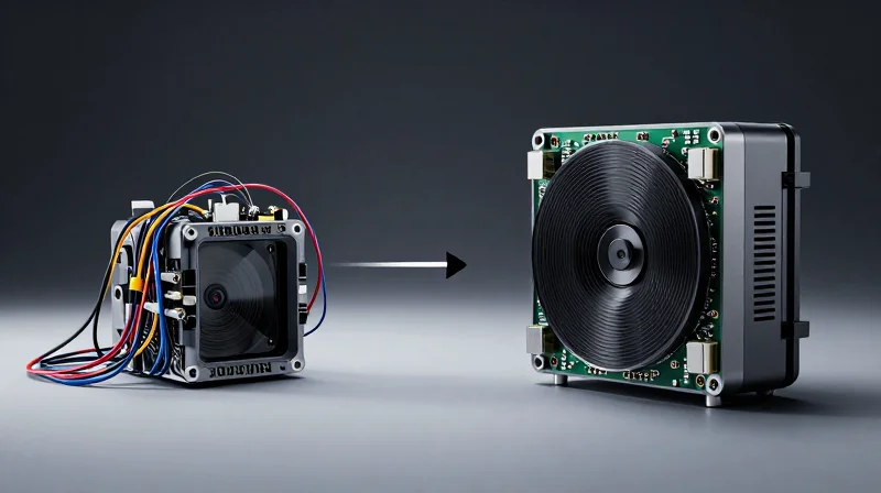
From Prototypes to Integrated Systems
Early LiDAR systems were characterized by massive, disparate components tethered by complex cable harnesses and standard rigid PCBs. This modularity was necessary for initial proof-of-concept stages, but it posed significant challenges for heat dissipation, signal integrity, and spatial efficiency. As the automotive industry mandates smaller form factors that can seamlessly integrate into rooflines and vehicle grilles, the transition to rigid-flex PCB technology has become the defining shift in sensor manufacturing.
Technical Comparison: Traditional Rigid vs. Rigid-Flex
| Feature | Traditional Rigid-Only | Rigid-Flex Architecture |
|---|---|---|
| Connectivity | Cable harnesses and connectors | Integrated circuits/folded substrates |
| Space Efficiency | Low (bulky housing required) | High (compact, fold-to-fit) |
| Signal Integrity | Susceptible to EMI in cables | High stability via continuous paths |
| Reliability | High failure point at connectors | Superior due to fewer solder joints |
Key Drivers of Modular Innovation
- Why is connector reduction critical?
Traditional connectors are common failure points due to vibration; rigid-flex eliminates multiple connectors, drastically increasing long-term operational durability. - How does rigid-flex optimize thermal management?
By utilizing thin, flexible substrates, heat can be dissipated across the entire surface area of the chassis more efficiently than through concentrated, localized rigid components. - What is the impact on assembly time?
Rigid-flex technology allows for complex 3D routing that replaces manual cable assembly, enabling robotic high-speed manufacturing lines.
The evolution of LiDAR modularization is not merely a design preference; it is a necessity for the mass adoption of autonomous hardware. By adopting rigid-flex interconnects, manufacturers achieve a level of spatial density and signal reliability that legacy methods simply cannot match, marking the end of the prototype-heavy era.
Limitations of Traditional Rigid-Only Interconnects
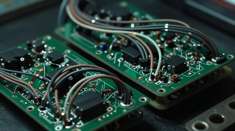
The Mechanical Fragility of Rigid Interconnects
Rigid-only assemblies, while robust in static environments, rely heavily on bulky board-to-board connectors and rigid ribbon cables to facilitate signal transmission between decoupled PCB sections. In automotive LiDAR systems, where sensors are subject to constant vehicular vibration and mechanical shock, these connection points become critical failure modes. The weight and stiffness of rigid connectors introduce mechanical stress concentrations at the solder joints, leading to fatigue, contact oxidation, and, eventually, intermittent electrical connectivity failures that can render a LiDAR unit non-functional.
Spatial Constraints and Thermal Impedance
As LiDAR modules shrink in size to improve vehicle aerodynamics and integration aesthetics, rigid interconnects create significant spatial bottlenecks. Rigid boards require specific mechanical clearance for connectors and cable routing, often forcing larger module housings. Furthermore, the use of auxiliary cables creates airflow blockages, hindering effective heat dissipation in dense sensor arrays. This thermal trapping accelerates component degradation and impacts the signal-to-noise ratio of sensitive optoelectronic components.
Comparative Limitations
| Limitation Category | Rigid-Only Interconnect Impact | Resulting Risk |
|---|---|---|
| Vibration/Shock | High stress on connectors | Intermittent signal loss/joint fatigue |
| Form Factor | Bulkier, rigid geometry | Limited design flexibility |
| Thermal Management | Connector-induced air blockage | Increased operating temperatures |
| Assembly Complexity | Manual connector mating required | Higher risk of human assembly error |
Common Challenges FAQ
- Why are board-to-board connectors problematic for LiDAR?
These connectors act as mechanical leverage points; when the vehicle vibrates, the inertia of the rigid board causes the connector pins to flex or lose contact, leading to signal degradation. - Does rigid-only design impact sensor calibration?
Yes. Mechanical shifts caused by thermal expansion or vibration in rigid interconnects can misalign the emitter-receiver relationship, necessitating frequent recalibration or causing data drift. - Is weight a significant factor in rigid interconnects?
The combined weight of multiple rigid boards, connectors, and heavy shielding components increases the total mass of the LiDAR unit, which is detrimental to chassis vibration damping and packaging requirements.
Defining Rigid-Flex Architecture
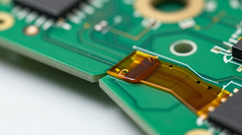
The Architecture of Rigid-Flex Systems
Rigid-flex architecture represents a paradigm shift in LiDAR sensor design by combining the mechanical stability of FR-4 rigid boards with the dynamic adaptability of flexible circuits. Unlike traditional rigid-only assemblies that rely on vulnerable ribbon cables or bulky wire harnesses to bridge signal paths, a rigid-flex PCB is a singular, monolithic interconnect solution. It consists of internal flexible polyimide layers that transition seamlessly into rigid sections, allowing the entire system to fold or wrap within the confined volume of a high-performance LiDAR housing.
Core Components and Material Composition
The performance of rigid-flex designs in automotive and industrial LiDAR stems from high-performance materials designed to withstand harsh environmental cycles. Key components include:
- Polyimide Substrates
These flexible dielectric layers offer excellent thermal stability and chemical resistance, ensuring the circuit maintains integrity under vibration and thermal expansion. - Plated Through-Holes (PTH)
Modern rigid-flex designs utilize specialized plating processes in transition zones, creating reliable electrical paths between the rigid and flexible layers without the risks of cracking associated with traditional interconnects. - Coverlays
Instead of traditional solder masks, flexible sections use adhesive-backed polyimide films to protect the circuit, providing superior bending fatigue resistance.
Rigid vs. Rigid-Flex Comparison
| Feature | Rigid-Only + Harness | Rigid-Flex Architecture |
|---|---|---|
| Mechanical Reliability | Moderate (connector failure points) | High (integrated/monolithic) |
| Spatial Efficiency | Low (bulky connectors) | Very High (3D folding capability) |
| Signal Integrity | Susceptible to EMI at connectors | Superior (continuous trace routing) |
| Assembly Complexity | High (manual harness routing) | Low (reduced assembly steps) |
Key Design Considerations
To fully leverage rigid-flex technology in LiDAR, engineers must prioritize controlled impedance routing and bending radii optimization. Because LiDAR systems often process high-speed LVDS or Ethernet data, the continuity of ground planes across the rigid-to-flex transition is critical to preventing electromagnetic interference (EMI). Furthermore, defining the 'bend area' early in the design cycle allows for precise copper weight management, ensuring the circuit can withstand the necessary mechanical stress without compromising signal throughput.
Weight and Spatial Advantages in Autonomous Vehicles
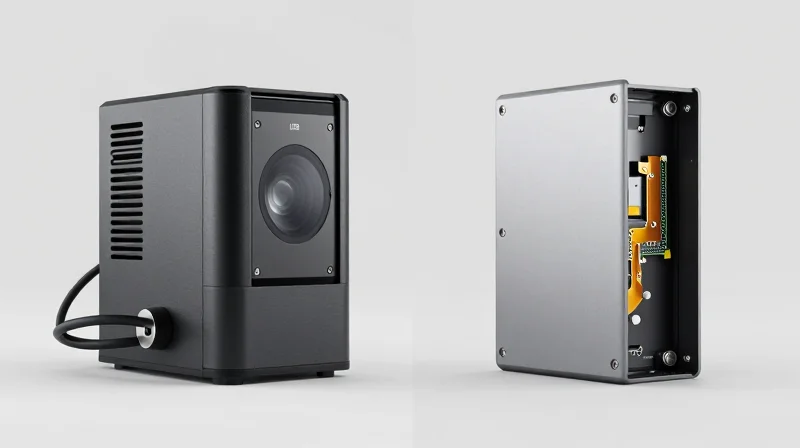
Weight Reduction Through Strategic Consolidation
Traditional interconnect methods for LiDAR rely heavily on bulky mechanical connectors, thick cabling harnesses, and rigid PCB-to-PCB backplanes. Each of these components contributes to significant parasitic mass that complicates vehicle dynamics. By replacing these discrete mechanical interfaces with integrated rigid-flex circuits, designers can eliminate heavy cable housings and metallic connector pins. This transition does not merely shave off grams; it allows for a streamlined, single-piece assembly that achieves the same electrical connectivity with a fraction of the hardware weight.
Spatial Optimization and Form Factor Versatility
Autonomous vehicles require LiDAR systems that fit into tight aerodynamic contours, such as roof pillars or front grill assemblies. Rigid-only PCBs enforce strict planar requirements, leading to excessive 'dead space' around the sensor module. Rigid-flex technology utilizes flexible polyimide layers that can be folded or contoured, allowing the electronics to conform to the sensor's enclosure shape. This utilization of 3D spatial design reduces the total volume occupied by the LiDAR unit by up to 40%, facilitating seamless integration into sleek automotive designs without compromising sensor performance.
Comparative Efficiency Matrix
| Feature | Traditional Rigid-Only | Modern Rigid-Flex |
|---|---|---|
| Connector Weight | High (Heavy mechanical shells) | Negligible (Direct solder interfaces) |
| Spatial Footprint | High (Planar limitations) | Low (3D conformal capability) |
| Assembly Reliability | Low (Connector fatigue) | High (Monolithic design) |
| Package Volume | Large (Requires clearance) | Compact (Custom geometry) |
Technical FAQ
- How does rigid-flex tech improve vibration resistance?
By replacing multiple connectors with continuous flexible traces, the assembly eliminates common failure points where mechanical pins vibrate loose, significantly improving signal integrity in high-vibration automotive environments. - Does weight reduction impact the thermal dissipation of LiDAR?
Actually, it improves it. Rigid-flex designs allow for better thermal path management by enabling direct heat sinking against the chassis, whereas heavy, insulated cabling often acts as an unintended thermal barrier. - Is the complexity of manufacturing rigid-flex worth the space savings?
Yes. While the fabrication of rigid-flex is more intricate, the reduction in assembly time and parts inventory often results in lower total cost of ownership and superior vehicle-level packaging efficiency.
Signal Integrity and Reliability Benchmarking
Signal Integrity: Minimizing Impedance Discontinuities
Signal integrity in high-speed LiDAR systems is highly sensitive to parasitic capacitance and impedance mismatching introduced by traditional board-to-board connectors. Mechanical connectors create signal bottlenecks and reflections as transitions move through contact pins and header housings. By contrast, rigid-flex technology employs continuous, integrated signal traces that transition from rigid substrates to flexible polyimide layers without physical interruptions. This monolithic approach minimizes trace impedance variations, significantly reducing signal attenuation and ensuring high-fidelity data transmission required for real-time autonomous point-cloud generation.
Reliability Benchmarking: Mechanical vs. Solder-Bonded Connections
| Failure Factor | Mechanical Connectors | Rigid-Flex Interconnects |
|---|---|---|
| Vibration Fatigue | High risk of fretting corrosion | Excellent, vibration-damping flexible interface |
| Thermal Cycling | Potential for contact loosening | Stable, homogeneous coefficient of expansion |
| Connection Density | Limited by pin pitch | High, optimized by trace routing |
| Mean Time Between Failure | Lower due to contact wear | Higher due to permanent bond |
Common Reliability Concerns in LiDAR Interconnects
- How do connectors impact long-term reliability in automotive environments?
Mechanical connectors are vulnerable to fretting corrosion caused by constant automotive road vibrations. Over time, micro-movements erode contact surfaces, leading to intermittent signal drops and complete sensor failure. - Why is a solder-bonded rigid-flex connection superior for harsh conditions?
By replacing physical connectors with permanent copper trace paths, rigid-flex designs eliminate points of failure. The inherent flexibility of the polyimide base layer absorbs mechanical stress, preventing the solder joints from cracking under thermal expansion or heavy shock. - Does rigid-flex complexity negatively affect signal latency?
No; in fact, the elimination of connector overhead simplifies the transmission path. Shorter, cleaner electrical paths reduce the need for error-correction overhead, effectively decreasing total system latency in data-intensive LiDAR operations.
Thermal Management and Heat Dissipation Strategies
Thermal Dynamics in LiDAR Interconnects
LiDAR processing units generate significant thermal loads due to high-speed data throughput and laser driver operation. Traditional rigid-only systems rely on mechanical connectors that act as thermal insulators and points of resistance, creating localized hotspots. Rigid-flex PCBs mitigate this by utilizing copper layers that extend continuously across the transition between board sections, acting as an efficient thermal conduit that dissipates heat away from sensitive sensor components.
Comparative Thermal Performance
| Feature | Rigid-Only + Connectors | Integrated Rigid-Flex |
|---|---|---|
| Heat Dissipation Path | Interrupted by connectors | Continuous thermal plane |
| Contact Resistance | High (increases with heat) | Low (solder-bonded joints) |
| Thermal Mass | Concentrated at connection points | Distributed across flex polyimide |
Heat Dissipation Advantages of Rigid-Flex
The implementation of rigid-flex substrates allows design engineers to utilize the entire surface area of the flexible sections for thermal heat sinking. Unlike rigid-only designs that require separate bulky heat spreaders, rigid-flex circuits can integrate thermally conductive vias and thicker copper ground planes directly into the flex area, facilitating a more uniform thermal profile across the entire sensor assembly.
Frequently Asked Questions
- How does polyimide influence thermal management?
Polyimide is highly stable at high temperatures, allowing it to maintain mechanical integrity under the thermal stress of sustained LiDAR operation without compromising the electrical signal path. - Do connectors contribute to thermal failure?
Yes. Mechanical connectors often suffer from 'fretting corrosion' exacerbated by heat-induced expansion and contraction, which increases contact resistance and accelerates thermal runaway. - Can rigid-flex designs incorporate external heat sinks?
Absolutely. Rigid-flex boards allow for direct mounting to aluminum chassis components, providing a shorter, low-resistance path for heat transfer from the processor to the vehicle frame.
Manufacturing and Cost-Benefit Analysis
Manufacturing Economics: Rigid-Flex vs. Rigid-Only
While rigid-flex PCBs command a higher initial unit cost compared to traditional rigid boards combined with discrete cabling, the long-term economic model favors rigid-flex through dramatic reductions in labor, assembly errors, and field failures. Transitioning to rigid-flex effectively consolidates multiple components—connectors, wires, and secondary PCBs—into a single, integrated assembly. This elimination of manual wiring steps not only accelerates production throughput but also drastically mitigates the risks associated with human error during complex LiDAR sensor integration.
| Metric | Rigid-Only + Connectors | Rigid-Flex Technology |
|---|---|---|
| Unit Cost | Low | High |
| Assembly Labor | High (Manual) | Low (Automated) |
| Failure Points | High (Connectors) | Low (Integrated) |
| Space Efficiency | Low | High |
ROI and Long-Term Value Drivers
The return on investment for LiDAR manufacturers is realized through the 'hidden' costs of traditional methods. High-frequency vibration in automotive and industrial environments often leads to connector fretting and signal degradation. By adopting rigid-flex, manufacturers realize significant savings by reducing warranty claims and the overhead associated with troubleshooting mechanical connection failures.
- Does the higher PCB price negate savings?
No. When accounting for the elimination of costly high-reliability connectors, wire harness assembly labor, and the potential for reduced yield loss, rigid-flex frequently lowers the total landed cost per unit. - How does integration impact time-to-market?
By streamlining the bill of materials (BOM), engineering teams reduce the complexity of the assembly process, allowing for faster prototyping and a more seamless transition to high-volume manufacturing. - What is the primary driver of failure reduction?
The transition from mechanical, friction-fit connectors to permanent, solder-bonded connections eliminates physical points of failure, which are often the primary cause of downtime in LiDAR systems.
Design for Reliability (DfR) Best Practices
Material Selection for Automotive-Grade Endurance
To achieve the high-cycle fatigue resistance required for LiDAR sensors exposed to constant vehicular vibration and thermal cycling, engineers must move beyond standard FR-4 materials. The transition to polyimide-based rigid-flex circuits provides superior thermal stability and flexible hinge durability.
| Material Property | Rigid-Only (FR-4) | Rigid-Flex (Polyimide) |
|---|---|---|
| Thermal Expansion (CTE) | High/Variable | Low/Stable |
| Vibration Resilience | Low (Stress Concentration) | High (Ductile Flex zones) |
| Moisture Absorption | Moderate | Extremely Low |
Design Parameters for Long-Term Reliability
Reliability is defined by the interconnect's ability to maintain signal integrity while undergoing millions of micro-vibrations. Implementing 'I-beam' construction or 'staggered' trace routing in the flex transition zones prevents copper work-hardening, a critical failure mode in rigid-only solutions.
- How do we prevent solder joint failure at the rigid-flex interface?
Utilize transition zones with balanced layer counts and apply strain-relief fillets or 'coverlay' reinforcements to distribute mechanical stress away from the junction. - What is the role of surface finish in DfR?
Electroless Nickel Immersion Gold (ENIG) or ENEPIG are preferred over HASL for their flat surface profile and superior resistance to oxidation during high-temperature thermal cycling. - How is vibration fatigue mitigated in high-density LiDAR?
Design flex sections with a 'neutral axis' approach, ensuring that traces are positioned at the center of the flex layer thickness to minimize strain during bending or vibration.
Future-Proofing Through DfR
As LiDAR systems move toward solid-state designs, the interconnect becomes a single point of failure. Adopting IPC-6013 Class 3 standards, coupled with rigorous HALT (Highly Accelerated Life Testing) protocols, ensures that the chosen rigid-flex architecture can survive the typical 10-15 year automotive operational window.
Transitioning to rigid-flex PCB technology is no longer just an aesthetic choice; it is a fundamental requirement for the next generation of autonomous sensor suites. By eliminating unnecessary connectors and optimizing internal packaging, engineers can achieve unparalleled reliability and spatial efficiency. Ready to optimize your sensor architecture? Contact our engineering team today to discuss your next high-performance interconnect project.
