Imagine a tiny component, often smaller than a fingernail, that plays a crucial role in countless electronic devices around us. The 220 ohm resistor, like a gatekeeper controlling the flow of electricity, is one such component. From the subtle glow of an LED in your phone to the complex workings of a larger circuit, this humble resistor plays a pivotal role. This article will guide you through the ins and outs of the 220 ohm resistor, its vital functions, color coding, and how to use it effectively. Let’s delve into the world of this ubiquitous electronic component.
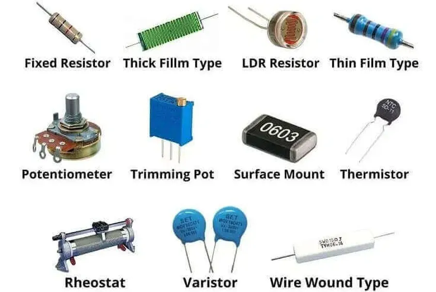
Resistors are fundamental passive electronic components that impede the flow of electrical current within a circuit. Their primary function is to introduce a specific electrical resistance, measured in ohms (Ω), to manage current flow, divide voltages, and perform other vital circuit operations. The 220 ohm resistor, a common component, exemplifies one of countless specific resistance values available for circuit design.
At their core, resistors control the relationship between voltage and current as defined by Ohm's Law (V = IR), where V is voltage, I is current, and R is resistance. This relationship is critical for circuit functionality, as resistors help ensure components receive the correct voltage and current levels.
Without resistors, circuits would be highly susceptible to damage from excessive current. Resistors are essential for the safe and reliable operation of all kinds of electronic devices.
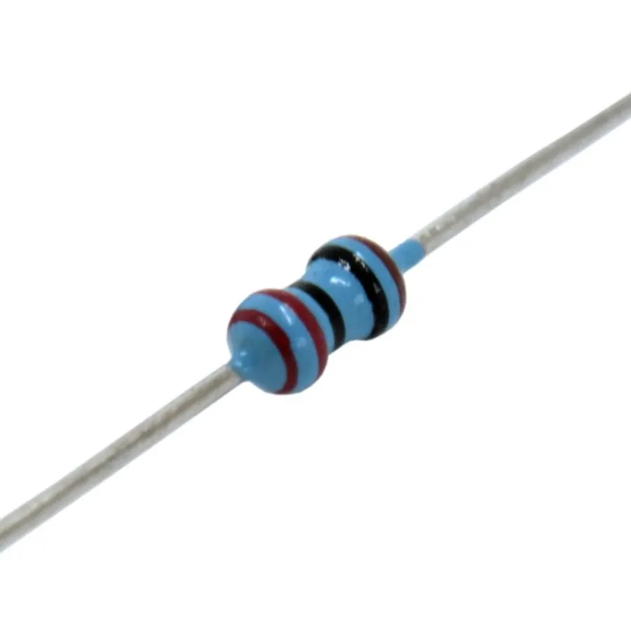
The 220 ohm resistor is a common and crucial value in electronics, frequently used for its ability to limit current effectively and protect sensitive components. Its prevalence stems from its suitability for numerous applications, particularly in conjunction with LEDs and various digital logic circuits, striking a balance between adequate current flow and component safety.
A key reason for the ubiquity of the 220 ohm resistor is its practical application in LED circuits. LEDs require a specific current to illuminate correctly and prevent damage from overcurrent. A 220 ohm resistor is often the appropriate choice to limit current to a safe range for common LEDs powered by typical voltage sources. Additionally, it serves as a standard value in many logic circuits where current limiting or signal conditioning is required. The availability of 220 ohm resistors in various package sizes and power ratings makes it a convenient and cost-effective choice for both hobbyist and professional electronics design.
| Application | Why 220 Ohms? | Benefits |
|---|---|---|
| LED Circuits | Limits current to a safe level for LEDs. | Protects LEDs from overcurrent damage; ensures proper illumination. |
| Logic Circuits | Provides necessary current limiting and signal conditioning. | Maintains proper signal levels; prevents component damage. |
| General Current Limiting | Offers a common value for various general purpose current limiting applications | Versatile and cost-effective; available in different forms |
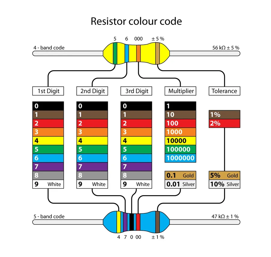
Decoding the color bands on a 220 ohm resistor is crucial for identifying its resistance and tolerance. This section provides a detailed guide on how to accurately interpret these color codes, ensuring correct component selection and usage in your electronic projects.
| Band | Color | Digit/Multiplier | Tolerance |
|---|---|---|---|
| 1st Band | Red | 2 | - |
| 2nd Band | Red | 2 | - |
| 3rd Band | Brown | 10^1 | - |
| 4th Band | Gold | - | ±5% |
For a 220 ohm resistor, the color bands are typically Red, Red, Brown, and Gold. The first two bands (Red, Red) represent the digits 2 and 2. The third band (Brown) is the multiplier, which is 10^1, effectively multiplying 22 by 10. This gives us 220 ohms. The fourth band (Gold) indicates a tolerance of ±5%. Understanding these color codes is fundamental in electronics for correct component identification and circuit design.
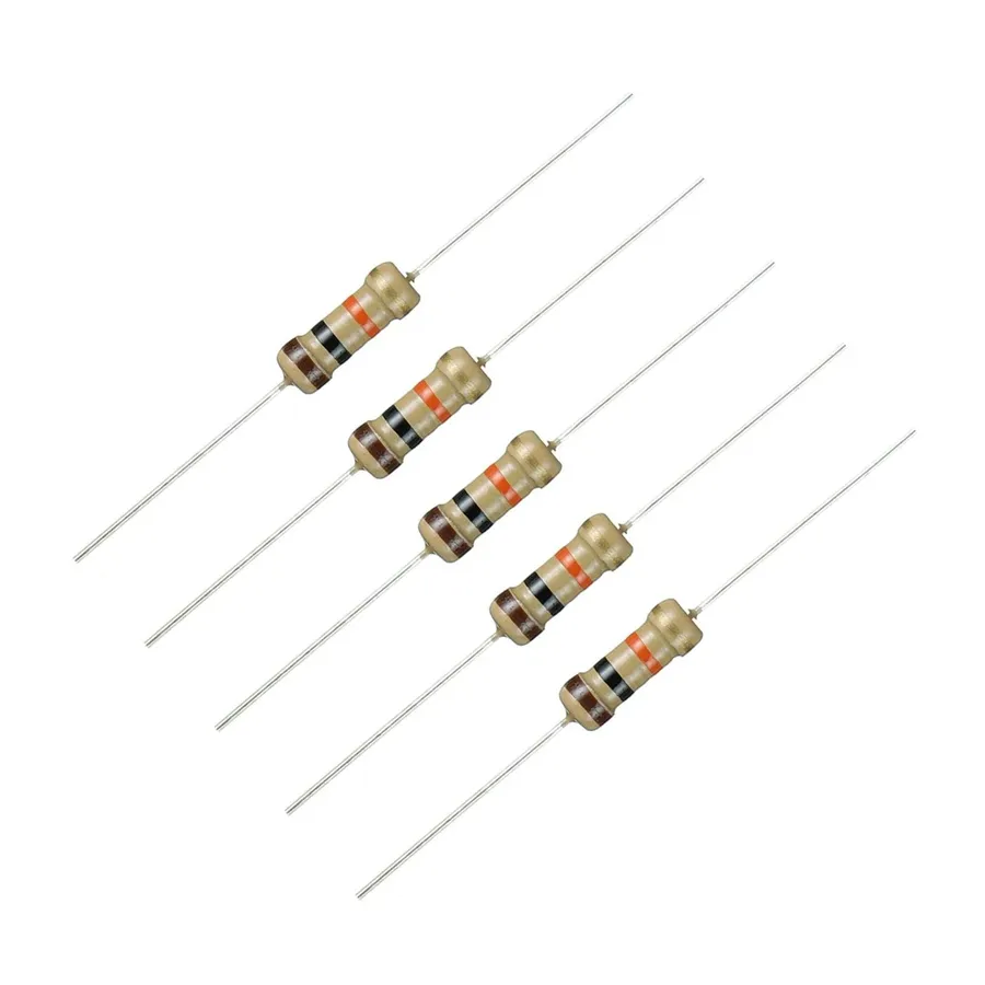
The 220 ohm resistor is a ubiquitous component in electronics, serving a critical role in current limitation and circuit protection across diverse applications. Its specific resistance value makes it ideal for various tasks, particularly in LED circuits, general electronic projects, and microcontroller-based systems.
| Application | Purpose | Benefit |
|---|---|---|
| LED Circuits | Current limitation for LEDs | Prevents LED burnout, ensures proper brightness |
| Basic Electronic Circuits | Setting bias points, voltage division | Enables control and predictable circuit behavior |
| Arduino Projects | Current limitation for LEDs, digital inputs | Allows safe and predictable interaction with microcontrollers. |
| Signal Line Protection | Over Current / Short Circuit Protection | Reduces risk of damage to other components, and prevents excessive currents |
| Transistor Circuits | Limiting Base Current | Ensures transistors operate within safe parameters, prevents over current conditions |
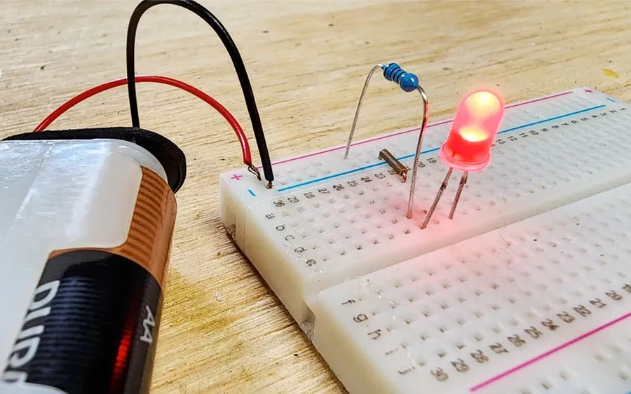
A 220 ohm resistor plays a crucial role in LED circuits, primarily acting as a current-limiting device to protect the LED from excessive current flow, which can lead to damage or premature failure. This section details the significance of this resistor, it's function, and the consequences of using an incorrect resistor or forgoing the resistor altogether.
LEDs (Light Emitting Diodes) are current-driven devices; unlike incandescent bulbs which are driven by voltage. An LED, when connected directly to a power source without a current-limiting resistor, will draw an enormous amount of current, resulting in overheating and rapid burnout. A resistor in series with the LED limits the current to a safe operating level, ensuring both the longevity and correct functioning of the LED.
The 220 ohm value is commonly selected for use with LEDs due to the typical forward voltage drop and current requirements of a range of common LEDs. For example, a typical red LED might have a forward voltage drop of around 2V and require a forward current of 20mA for optimal operation. When using a 5V supply, a 220 ohm resistor is well placed to limit the current to 20mA and protect the LED. The exact value required may vary depending on the LED and the supply voltage.
Calculating the required resistor value can be accomplished using Ohm's Law: V = IR, where V is voltage, I is current, and R is resistance. To calculate the correct resistor, rearrange the equation to R = V / I. You will need to determine the source voltage (Vs), the LED's forward voltage drop (Vf), and the desired LED current (I). The voltage across the resistor (Vr) is calculated as Vr = Vs - Vf. Then, you can determine the required resistance (R) with R= Vr/I. It is important to select a resistor with sufficient power rating, calculated using the formula P = I²R. A higher power rating will result in less heating of the resistor. It is standard practice to specify a resistor with a power rating considerably more than the calculated power dissipation.
| Parameter | Description |
|---|---|
| Vs | Source voltage (Volts) |
| Vf | Forward voltage drop of the LED (Volts) |
| I | Desired current through the LED (Amps) |
| Vr | Voltage across the resistor Vr = Vs - Vf (Volts) |
| R | Required resistance R= Vr/I (Ohms) |
| P | Power dissipated by resistor P = I²R (Watts) |
Choosing the appropriate 220 ohm resistor involves considering several key factors beyond just its resistance value. These factors ensure the resistor functions correctly within your circuit, providing the desired performance and preventing premature failure. The primary considerations include power rating, resistor type, and tolerance.
| Characteristic | Description | Impact on Selection |
|---|---|---|
| Power Rating | The maximum power a resistor can safely dissipate as heat, measured in Watts (W). | Must be greater than the expected power dissipation in the circuit to prevent overheating and failure. Calculate using P=I²R or P=V²/R, with a safety margin (typically 2x). |
| Resistor Type | Common types include carbon film, metal film, and wire-wound resistors. | Carbon film is general-purpose and cheap but less precise than metal film, which provides better temperature stability and tolerance. Wire-wound resistors are used for higher power applications. |
| Tolerance | The precision of the resistor's actual resistance compared to its nominal value (220 ohms), expressed as a percentage (e.g., ±1%, ±5%). | A lower tolerance (e.g., 1%) provides more precise resistance, which is crucial in circuits requiring accurate values. A higher tolerance (e.g., 5%) is acceptable for less critical applications. |
For example, in an LED circuit, if the resistor is dissipating 0.1W, you should select a resistor rated for at least 0.2W (allowing a margin for error and variations). For a simple circuit requiring moderate precision, a 5% tolerance resistor may suffice, but for precision applications, you should consider a metal film resistor with 1% or even 0.1% tolerance. In high-power scenarios, use a wire-wound resistor to withstand higher currents without failing.
This section addresses common inquiries regarding 220 ohm resistors, providing concise answers to help clarify their use, characteristics, and applications in electronic circuits.

Sourcing 220 ohm resistors is straightforward due to their common use. When purchasing, consider factors such as the quantity needed, desired tolerance, power rating, and resistor type, to ensure they meet the specific requirements of your projects. These components are readily available from a variety of vendors, both online and in physical stores.
| Factor | Description |
|---|---|
| Quantity | Purchase enough for current and future projects to save costs. |
| Tolerance | The accuracy of the resistor's value. Common tolerances are 1%, 5%, or 10%. Choose based on application needs. A 1% tolerance offers the most precision. |
| Power Rating | Indicates the maximum power the resistor can dissipate without overheating. Standard ratings are 1/4W or 1/2W. Choose a resistor with a sufficient rating. |
| Resistor Type | Options include carbon film, metal film, and wire-wound. Metal film resistors generally have higher precision and lower noise than carbon film. |
| Physical Size | Resistor size corresponds to its power rating. Ensure the resistor fits in the design. |
While the 220 ohm resistor is a common value, situations may arise where a direct replacement is unavailable. Understanding suitable alternatives and equivalent configurations ensures circuit functionality and flexibility in design. This section explores these possibilities, focusing on single resistor alternatives and resistor networks.
When a 220 ohm resistor is not immediately accessible, resistors with values close to 220 ohms can be used, considering the acceptable tolerance for the specific application. Standard resistor values are manufactured within specified tolerances, and slight variations may be inconsequential. For precise applications, resistor networks offer a viable solution.
| Alternative Resistor Value | Impact on Circuit Behavior | When to Consider | Trade-offs |
|---|---|---|---|
| 200 ohm | Slightly less resistance, results in marginally higher current flow. | Where slightly more current is acceptable and can be tolerated. | Increased current flow, could impact the lifespan of the circuit depending on other factors. |
| 240 ohm | Slightly more resistance, results in marginally lower current flow. | Where slightly less current is acceptable or needed. | Reduced current flow, might not meet power demands of circuit, such as in a LED circuit. |
| 270 ohm | More resistance, results in lower current flow. | When more current reduction is acceptable or there is a need for lower current flow. | Reduced current flow, could affect the performance of the circuit. |
| 180 ohm | Less resistance, results in higher current flow. | If the circuit can tolerate the higher current, or if the need is for higher current. | Increased current flow, could exceed the component's current rating. |
Resistor networks, combinations of series and parallel resistors, offer precise resistance values. In a series configuration, the total resistance is the sum of individual resistors. In a parallel configuration, the inverse of the total resistance equals the sum of the inverse of each individual resistor. Through careful calculation, one can combine readily available resistor values to synthesize a 220 ohm resistor (or close to it). A simple solution is to use two 110 ohm resistors in series to create a 220 ohm resistor, however this is not a standard value and might be difficult to find. Therefore, using other combinations like two 470 ohm resistors in parallel to achieve 235 ohms can be a solution. For higher precision, combining multiple resistors can be a good choice, however, the complexity of the solution needs to be balanced with the accuracy and precision.
When selecting an alternative, the power rating of the substitute resistor or the combination of resistors must be adequate for the application to avoid damage or overheating. Additionally, resistors of the same type (e.g., metal film or carbon film) should be used in networks to maintain uniform characteristics. The choice of an alternative should always be driven by application requirements, considering the accuracy, stability, and safety of the circuit.
The 220 ohm resistor, while seemingly simple, is a cornerstone of electronics. Understanding its color code, typical uses, and selection criteria allows you to use it effectively in your projects. Whether you're a hobbyist experimenting with LEDs or an engineer designing intricate circuits, the 220 ohm resistor's ability to precisely control current flow is an essential aspect of electronics. As a foundational component, mastering the use of the 220 ohm resistor unlocks the potential for a wide array of electronic applications and projects.

